Trunks
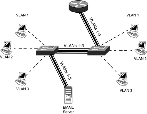
| The previous sections discussed interfaces that belong to only one VLAN. These are sometimes referred to as access links and are completely transparent to the users. The users have no knowledge of the existence of the VLAN. However, to maintain VLAN information, the originating frame from a user must contain VLAN information that the switch fabric can use to forward the frame. Frame TaggingAs a frame enters the switch fabric, it's encapsulated or tagged with some additional information that identifies VLAN properties for the frame as it is switched through the switch fabric. This includes the VLAN ID or number, sometimes referred to as the VLAN color. This additional information remains on the frame as it's forwarded across the switched backbone from switch to switch. A trunk link is a connection between two trunk-capable devices. These devices could be two switches, a switch and a router, or even a switch and an end station. Trunking essentially extends the backplane of the switch. Normally, only traffic from one VLAN can be associated with a port. The exception to this is a trunk port. A trunk port allows multiple VLANs to cross it to a neighboring device, unlike an access link. Trunking is performed by encapsulating or tagging frames in hardware by the ASICs on each port. Encapsulating or tagging adds information, such as the VLAN number, to help in the forwarding of the frame by other switches. By default, trunk links carry all VLAN traffic, but you can restrict which VLANs can traverse a trunk. The additional VLAN information remains on the frame until it reaches its destination port, where it is then stripped off. This whole process occurs at Layer 2 and is completely transparent to the user. At both the source and destination, the users see the original frame, but as the frame is forwarded between switches, the additional VLAN information is also seen. Unlike an access (user) port that does not understand the frame encapsulating or tagging added by a switch, a trunk port expects that the device at the other end of the connection does understand the frame tagging. Standard Ethernet cards do not understand the additional VLAN information that's been added to or inserted into a frame. When carrying information from many VLANs between switches, you need this type of link. The destination switch somehow needs to know what VLAN the frame originated from so that it does not forward the frame out incorrect ports. You would not want a broadcast from one VLAN to be propagated to other VLANs. In certain cases, as shown in Figure 3.3, it even makes sense to buy a special card that does understand the tagging for an end station. Figure 3.3. Tagging can be done between trunk-capable NICs, including switches, routers, and file servers.
In a switched network, many clients from different VLANs might access an enterprise resource, such as an email server. By having only a standard Ethernet NIC, the file server can belong to one, and only one, VLAN. Clients that belong to a different VLAN would have to send their traffic to a router, and the router could then forward the frames to the email server. The problem with this approach is the latency that the router introduces. In the case of email, users will not notice this latency. But with a client/server, database, or voice or video application, users might notice the latency. For this reason, it would be nice to place a special NIC card in the file server that actually understands multiple VLANs in essence, to make it a trunk connection. With this special NIC, an end station would not have to send its frame to the router first, but could bypass it completely to access the file server. Likewise, it makes sense to have a special NIC like this in a router. Without this card, a router would need a separate interface for each VLAN that exists in the switched network to route between the VLANs. With a trunk NIC interface, a router would only need one interface, thus greatly reducing the cost requirements of the router. You could also implement Multilayer switching to solve your Layer 3 latency problems. ProtocolsOne important aspect of VLANs is for the switch fabric to carry the VLAN information across different media topologies, such as Ethernet, token ring, FDDI, and ATM. Here are the four VLAN tagging mechanisms supported by Cisco:
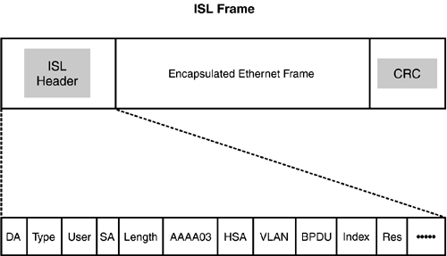
Please note that not all Cisco devices support all the preceding trunking protocols. For example, Cisco's Catalyst 1900 switches support only ISL, the Catalyst 2950s support only 802.1Q, and the discontinued Catalyst 5000s supported all four. With FDDI, the Security Association Identifier (SAID) is used to carry VLAN information across a FDDI backbone. This book focuses on Cisco's ISL and IEEE's 802.1Q trunking protocols. ISLISL is a Cisco-proprietary technology for trunking VLANs at Layer 2. Unlike normal Ethernet NICs, ISL cards cost more because specialized ASICs and processors are included to support the framing encapsulation at gigabit speeds. ISL adds a 26-byte header and a 4-byte trailer (which is a CRC) to the original Ethernet frame, for a total of 30 bytes. Figure 3.4 shows a picture of an ISL frame. Figure 3.4. ISL frame format.
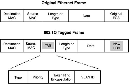
Some of the items included in the header are the source and destination MAC address that are duplicated from the original frame, the type of frame (Ethernet, FDDI, token ring, or ATM), the priority of the frame, the length of the frame (not including the CRC), and the VLAN number (located in the VLAN ID field). The BPDU field is a one-bit descriptor that signifies that the encapsulated frame is either a Spanning Tree Protocol (STP), Bridge Protocol Data Unit (BPDU), or Cisco Discover Protocol (CDP) information, or is a normal Ethernet frame. There are two Field Checksum Sequence (CRC) fields in an encapsulated frame one for the original Ethernet frame and one for the ISL header and encapsulated Ethernet frame. ISL requires a special Ethernet NIC that not only understands the VLAN information in ISL frames but also allows the NIC to add VLAN information to frames. Some Cisco routers support ISL, some of Cisco switches support ISL, and third-party companies, such as Intel, produce ISL NICs. From an end station's perspective with an ISL NIC, the software driver that's loaded on the machine creates the illusion that there are many logical cards connected to different Ethernet segments. The user would configure each logical card with the appropriate network address that reflects the VLAN to which the logical card belongs. When setting up a trunk connection with ISL, both sides must be configured with the same encapsulation. If one side is set to ISL and the other is set to a normal Ethernet frame encapsulation, the normal Ethernet NIC won't understand the VLAN tagging, and will mistake it for a normal Ethernet frame. The problem that this typically causes is that a normal Ethernet frame can be up to 1518 bytes in length, and ISL adds 30 bytes. If the MTU was set to 1500 for the data, and 18 bytes for the MAC header information and FCS, when you add 30 bytes for the ISL information, you exceed the maximum valid MTU size for an Ethernet frame (1548). A normal Ethernet NIC would see this kind of frame as a giant and drop it. 802.1QEarly in the summer of 1998, the IEEE standardized the frame tagging process for trunking VLANs and produced the 802.1Q standard. One problem with Cisco's ISL frame encapsulation process is that other switching vendors do not support it. In almost all cases, each vendor implements VLANs differently, thus making it nearly impossible to use switches from more than one vendor. Today, companies are no longer restricted to sticking with just one vendor for their switching purchases. This is especially important with the great flux of changes occurring in today's industry. If a new switching technology becomes available from a startup company, it becomes much easier to integrate it into a corporation's existing switched network. You no longer have to wait months for your preferred switching vendor to either parallel the new technology or buy rights to it. Both ISL and 802.1Q add VLAN information to the Ethernet frames explicitly. However, how they perform this process is different. With ISL, a 26-byte header and a 4-byte trailer are added to the frame; the original frame is not modified. This process is referred to as encapsulation. With 802.1Q, the actual frame is modified or tagged. To denote VLAN information, a 4-byte Tag Protocol Identifier (TPID) and a 2-byte Tag Control Information (TCI) are inserted between existing fields in the Ethernet frame, shown in Figure 3.5. Figure 3.5. 802.1Q frame format.
Because the information is inserted into the original Ethernet frame, the original frame's CRC is regenerated to accommodate the change. The advantage of using the 802.1Q tagging process over ISL is that, in an ISL trunking environment, ISL-aware cards must be used because a frame could be larger than 1518 bytes the maximum size of an Ethernet frame. With 802.1Q, the frame size is only increased by 4 bytes and can be forwarded by a non-802.1Q aware device. Because of the tagging information placed into a frame, 802.1Q provides some advantages over ISL:
Native VLANs802.1Q trunks support a native VLAN. A native VLAN is one that does not tag frames. This is different from ISL, where all VLANs that traverse the trunk carry VLAN information. Actually, a native VLAN has the following criteria:
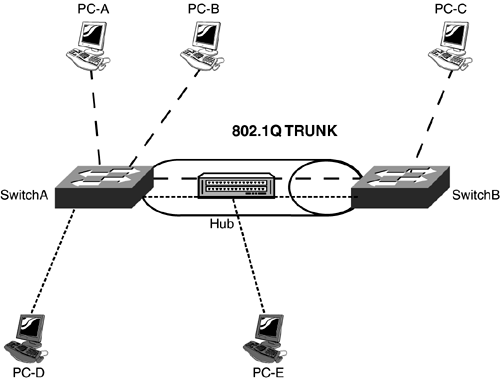
One advantage that native VLANs provide is that you can have both 802.1Q and non-802.1Q devices on the same trunk connection, as is shown in Figure 3.6. In this example, assume the native VLAN is 1 and that PC-D and PC-E are in this VLAN. As you can see from the figure, there is an 802.1Q trunk between the switches, but a hub is providing connectivity. Plus, PC-E is connected to this hub. For PC-E to send traffic to PC-D, PC-E either needs an 802.1Q NIC or must be placed in the native VLAN. The other PCs, PC-A, PC-B, and PC-C, are in another VLAN, such as VLAN 2, and can use normal NICs to communicate with each other. The trunk between the two switches tags frames from these devices with a VLAN 2 identifier. Figure 3.6. Native VLANs and trunking.
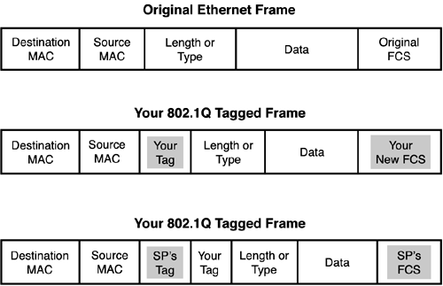
VLAN Ranges and MappingsISL supports VLANs numbered from 1 1005, where Ethernet-based VLANs can use numbers from 1 1001 to create VLANs. (1002 1005 are reserved for token ring and FDDI functions and cannot be deleted.) 802.1Q, on the other hand, has access to VLAN numbers ranging from 0 4095. 0 and 4095 are reserved for system uses, thus enabling you to use numbers from 1 4094 to create Ethernet VLANs. VLAN Services from Service ProvidersSome service providers allow for the tunneling of 802.1Q tagged frames through their networks. This enables you to use your own private VLAN numbers in your own networks, but still allow these tagged frames through the provider's network, which might also be using 802.1Q VLANs. This provides a huge advantage to service providers based on the number of customers that they have and the VLANs that these customers use. 4,096 VLANs sounds like a lot of VLANs and is more than sufficient for a single company, but imagine that you have thousands of companies connected to a provider's network perhaps with 10,000 VLANs among all of these companies. Of course, 802.1Q wouldn't be able to handle this when trying to keep all the VLANs straight among all the customers. However, 802.1Q supports a tunneling feature that enables you to keep your own VLAN numbers as they are transferred across someone else's network. For this process to take place, the original Ethernet frame is tagged twice: once by your own switch, and again by the provider's switches. Figure 3.7 shows an example of this double tagging. Figure 3.7. 802.1Q Double tagging.
As you can see in this example, the top frame is the original Ethernet frame and the middle frame is the frame that your switch tagged. The bottom frame is the one tagged by the service provider. With the second tagging, the service provider inserts its VLAN tag before your tag and then recomputes a new FCS value. When the frame exits the service provider's network and is forwarded to your remote site, the service provider removes its tag and recomputes the FCS value based on your original tagged frame. Through this process, your 802.1Q frame can be transmitted transparently through the service provider's network, based on its own internal VLAN configurations. The second tag that the provider adds is sometimes called a metro tag.
When using tunneling, BPDUs from your internal switches, CDP information, and VTP information can be tunneled through a carrier's network to your remote switch or switches, enabling you to treat the service provider's network as transparent (invisible). If your provider doesn't support tunneling, the provider either processes or drops this information, and forwards only user traffic. 802.1Q tunneling is discussed in more depth in Chapter 11, "Metro Ethernet." An alternative solution is the use of the Generic Bridge PDU Tunneling (GBPT) protocol. GBPT allows the service provider switch to change the original destination multicast address in the frame to a Cisco-proprietary one: 0100.0ccd.cdd0. This is then forwarded out all trunk connections in the native VLAN. One restriction of this feature is that when you enable GBPT on a port, frames from other enabled protocols are not sent out of the port.
Dynamic Trunk ProtocolTrunking negotiation is the process that takes place to determine whether two connecting devices can create a trunk connection. Dynamic ISL (DISL) was Cisco's old protocol that performed this (that is, it verified whether two connected ports could form a trunk). One large limitation of DISL was that it could perform the dynamic trunking negotiation only for ISL links; you had to manually configure 802.1Q trunks. DISL has been replaced by Cisco's proprietary Dynamic Trunking Protocol (DTP). DTP, like DISL, is a protocol that auto-negotiates whether trunking can be performed on the connection. Unlike DISL, DTP supports auto-negotiation of ISL and 802.1Q on trunk links. If two opposite ports use different encapsulation types, such as ISL and 802.1Q, they will not form a trunk: Both sides must use the same encapsulation. DTP supports five different trunking modes, as shown in Table 3.1. In this table, the DTP modes are the ones used with the switchport mode command, discussed later in this chapter. The Generate DTP Frames column indicates whether the DTP mode generates DTP frames on the interface (only trunk and dynamic desirable do this by default). The Trunking column indicates whether or not the interface is trunking (by default, only trunk and nonegotiate enable trunking). nonegotiate should be used on trunk connections where the remote device doesn't understand Cisco's proprietary DTP. The default trunking mode is dynamic auto, which means that the configuration of the remote interface determines whether the interface becomes a trunk or remains an access link connection.
Table 3.2 shows the combinations of modes that cause trunking to occur. Any other combination of modes causes the interface to act as an access link connection.
Configuring ISL and 802.1Q TrunksSetting up an ISL or 802.1Q trunk is very straightforward, as shown here in Listing 3.1. Listing 3.1 Trunk ConfigurationSwitch(config)# interface type slot_#/port_# Switch(config-if)# shutdown Switch(config-if)# switchport trunk encapsulation isl|dotq1 Switch(config-if)# switchport mode trunk|dynamic desirable| dynamic auto|nonegotiate Switch(config-if)# switchport trunk native vlan VLAN_# Switch(config-if)# switchport trunk allowed vlan add|except|all|remove VLAN_1, VLAN_2, etc. Switch(config-if)# no shutdown Even though it isn't necessary to disable an interface when enabling trunking, doing so is recommended. You must first specify either ISL or 802.1Q as the trunking type with the switchport trunk encapsulation command, shown in Listing 3.1, and then specify the trunking mode with the switchport mode trunk command. Refer to Table 3.1 for an explanation of the modes. The switchport trunk native command is applicable only to 802.1Q trunks and is optional. This command specifies the native VLAN number for the trunk. By default, this is VLAN 1. The switchport trunk allowed command is also an optional command. This command enables you to manually prune off VLANs from a trunk. By default, all VLANs are allowed to traverse a trunk. This is discussed in more depth in the "VTP Pruning" section later in this chapter.
Verifying Your Trunk ConfigurationThere are three commands you can use to verify your trunking configuration:
Let's take a look at the output of all three of these commands. Listing 3.2 shows an example of the first one. Listing 3.2 show running-config interface Example Switch# show running-config interface fastethernet 0/1 Building configuration... ! Current configuration: 33 bytes interface FastEthernet 0/1 switchport mode dynamic desirable switchport trunk encapsulation dot1q end This listing displays the trunking configuration of FastEthernet 0/1. Listing 3.3 shows an example of the show interfaces command with the switchport parameter. Listing 3.3 show interface switchport Example Switch# show interface fastethernet0/1 switchport Name: Fa0/1 Switchport: Enabled Administrative mode: dynamic desirable Operational Mode: trunk Administrative Trunking Encapsulation: dot1q Operational Trunking Encapsulation: dot1q Negotiation of Trunking: Enabled Access Mode VLAN: 1 (default) Trunking Native Mode VLAN: 1 (default) Trunking VLANs Enabled: ALL Trunking VLANs Active: 1,2 Pruning VLANs Enabled: 2-1001 <--output omitted--> This listing shows the switchport configuration of a specified interface. In this example, Fa0/1 is trunking with 802.1Q and the trunk mode is set to dynamic desirable. Listing 3.4 shows an example of using the trunk parameter. Listing 3.4 show interface trunk Example 2950# show interface fastethernet 0/1 trunk Port Mode Encapsulation Status Native vlan Fa0/1 desirable 802.1q trunking 1 Port Vlans allowed on trunk Fa0/1 1-1005 Port Vlans allowed and active in management domain Fa0/1 1-2,1002-1005 Port Vlans in spanning tree forwarding state and not pruned Fa0/1 1-2,1002-1005 The listing shows that one interface was set to a desirable DTP mode and formed a trunk with the remote device. Troubleshooting Trunk ConnectionsIf you're experiencing problems in setting up a trunk or having problems with an active trunk, examine the following pointers:
|
EAN: 2147483647
Pages: 171