Basic Wireless Location Determination Toolset
Wireless networks, regardless of the actual communication technology employed (802.11, 802.15, 802.16, GSM, W-CDMA, IS-95, and so on) all have the same basic set of characteristics that can be exploited to determine location. Later it will be shown how these tools can be applied to determine location in WLANs, and what additional tools can be used to solve some of the particular problems that arise in WLANs.
Nearest Transmitter or Access Point
The most basic method of location determination in a wireless network is to take the location of the nearest fixed transmitter (cell tower or access point) and use that. For cellular and WiMAX networks that have a range measured in kilometers, this is a fairly crude method that is only used when there is insufficient time or measurement capability to employ more accurate methods. A WiFi network typically has a short range (on the order of 100 meters in most cases) with modest increases from 802.11n and other technological advances. A shorter range makes this method far more accurate for WiFi networks.
This method usually results in a reasonably large area of uncertainty, which can prove to be a problem for ad hoc networks.
A number of solutions have appeared recently using a method that is based on access point identification. In these methods, a WiFi-enabled computer reports all the service set identifiers (SSIDs) in the area to a location determination system. The SSID is a 32-character identifier that helps distinguish between different WLANs in any area. Based on these SSIDs and a database of known locations, the system provides a location estimate. These location determination systems operate independently of any access network and use a centrally maintained database, of which a copy may be kept locally. However, using the SSID of local access points is very dependent on having multiple wireless LANs in the area, and the accuracy of the databases that are used is critical. These systems are limited to more densely populated areas.
Ranging Measurements
The distance between two wireless antennae can be determined based on the round trip time for a simple message. Such information can be used, particularly in wireless systems with a longer range, to help reduce the probability of the contention that can occur when two transmissions are sent at the same time.
Ranging measurements, particularly in smaller networks, require precise timing, considering that a radio signal travels one meter in less than 3.4 nanoseconds. Ranging measurements also rely on being able to compensate for any delays that the other end of the link may add in receiving a message, processing it, and preparing a response for transmission.
A major weakness of ranging measurements is their susceptibility to signal reflection, or multipath signals. Multipath occurs when a signal reflects off a surface between the transmitter and receiver. If a signal does not take the most direct path from transmitter to receiver, the perceived distance can be inflated. For wireless transceivers that are designed for communication purposes, a stronger signal is likely to be preferred over a weaker signal that might be received earlier.
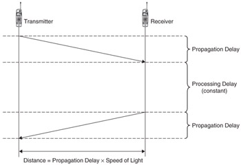
For 802.11 WLANs, ranging measurements rely on the requirement that an 802.11 receiver acknowledge frames that are addressed to it. This sort of message can be processed rapidly, and in a fashion that has a deterministic time. The processing time can be eliminated from the measurement if it is already known, (see Figure 7.3). Statistical methods can then be applied to multiple measurements to increase the confidence in the measurement.

Figure 7.3: Determining the distance between two transceivers.
A single range measurement for an omnidirectional transceiver reduces the overall area of uncertainty, or the precision of the estimate. The overall accuracy, whether or not the information is reliable, is not necessarily improved.
Trilateration
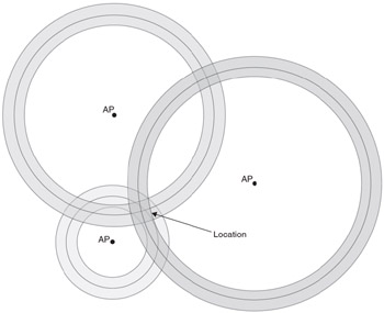
The most common way to use ranging measurements is to take multiple-range measurements from fixed or known points. These ranges are combined to determine a location using a technique called trilateration. Trilateration is where range measurements become the most useful, particularly where no other measurements are available. This method is particularly applicable where omnidirectional antennae are used. Figure 7.4 shows how this can be applied in two dimensions.

Figure 7.4: Using trilateration in two dimensions from three access points.
Three circles are drawn from the fixed points with the given distances. The first two circles intersect at two points; the third circle is used to determine which of the two points the target location is. This principle can be applied in three dimensions using spheres instead of circles, but one additional range measurement is required.
Sources of error in measurement mean that the circles do not always meet precisely. A region of uncertainty usually arises from trilateration methods. More measurements can be used to reduce this region in size.
Direction
Angle of arrival methods use shaped antennae or antenna arrays to determine which direction a signal was transmitted from. This permits a heading to be determined from an access point, or other transceiver. When combined with a range measurement, this can provide a reasonable location estimate from a single transceiver.
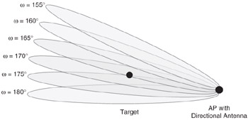
Directional antennae can be used to direct radio signals in a particular direction. The signal produced by some directional antennae can be controlled so that a narrow band can be transmitted. If the signal is rotated in a sweeping pattern in the same way that a radar system would be employed, then the location of another transceiver can be detected by determining which angles generate responses. The shaped signal isn't perfectly narrow, so several responses are likely to be generated, producing a range of angles. Figure 7.5 shows a possible scenario, where responses are generated for values of ω are 165, 170, and 175 degrees.

Figure 7.5: A directional antenna can be used like a radar system to determine a direction.
Multiple direction measurements from different points in the network can be combined to refine a location estimate. This is known as triangulation.
This method is best suited to dedicated ALEs within the network since this sort of process interferes with the ability of a node to communicate on its usual radio channel and exchange data. Specialized antennae and radio control are also required for this process.
Signal Strength Measurements
The strength of a radio signal from nearby transmitters can usually be measured at each receiver in the network. Primarily, this information exists to assist in regulating transmission power levels, but this information can also be used to determine the location of a receiver.
The received signal strength must then be compared to the transmission power. From this, a rough range estimate can be derived using the inverse square principle for signal (signal power is inversely proportional to the square of the distance from the transmitter). Statistical methods are often used to compensate for variations that can occur.
Signal strength can be highly variable since radio signals are highly susceptible to environmental conditions. Weather conditions outdoors, such as wind and rain can make signal strength unreliable, unless additional data are collected to compensate for these variations. More sophisticated methods also take environmental conditions into consideration. Signal strength can be used in combination with other methods, which provide information that can refine the accuracy of results.
Radio camera is a term often used to describe location determination methods that use signal strength alone to determine location. Radio camera techniques use a survey of the area with signal strength measurements. They are more reliable than a straight estimate based on the inverse square principle, which provides a range estimate subject to all the error sources mentioned previously. This method is called radio camera because it takes a map, or image, of the network coverage area, arranging signal strength measurements in a grid format. The nearest access point is used as a starting point and maximum likelihood estimation techniques are employed to match the measured signal strength to the best fit within the signal strength map nearest to the initial estimate.
For WiFi, the received signal strength indicator (RSSI) and received channel power indicator (RCPI) are statistical measures of signal strength.
Time Difference of Arrival (TDOA)
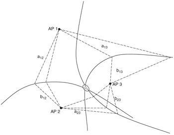
If the target mobile station generates a well-known signal or training sequence, a number of measurement units can observe the precise time that the signal was received. In two dimensions, three time differences can be combined to determine the location of the mobile station. The method used to determine the location estimate is called multilateration. Figure 7.6 shows how multilateration is performed based on the time difference of arrival (TDOA). The intersection of hyperbolic curves is used in a similar method to that used when range measurements are known. Each hyperbolic curve describes a point where the difference between the distances aij and bij are constant.

Figure 7.6: Time difference of arrival measurements used to determine location.
TDOA relies on having time synchronization between measurement units. This is typically achieved in cellular networks by including GPS receivers in each unit to provide an accurate time base derived from GPS time. For WiFi, time synchronization is already available within the network; infrastructure networks only have one wireless hop, which ensures good synchronization with little possibility of time skew. However, time synchronization across an ad hoc network can potentially take a short time to achieve; therefore, a time difference of one or two microseconds can be observed.
Like trilateration, more measurements can be used to refine location estimates that are produced by multilateration.
Two forms of time difference can be used for location estimation. In a network-based system, monitoring devices in the network capture an easily identifiable message that is transmitted by the device. Each monitoring device records the exact time that it receives the message. A device-based system is the exact inversion of network-based TDOA. The device measures the exact time that it receives signals from multiple points in the network. The device-based approach is complicated by the fact that the signals are transmitted at different times; these differences need to be known and accounted for. Both network- and device-based methods result in a similar multilateration calculation.
EAN: 2147483647
Pages: 129