Modifying a Shape
| [ LiB ] |
Modifying a Shape
To really exploit the power of vectors, try the Pen tool's Edit mode. Any vector object is made up of at least two nodes, with pairs of nodes connected by segments. Entering Edit mode gives you access to an object's nodes, enabling you to reshape and refine the object.
The best way to learn about node editing is to jump right in, so let's try working through an extended example.
Node Editing
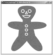
With the Pen tool's Edit mode, you can make complex shapes from relatively simple shapes . For example, starting with a five-pointed star, you can make a gingerbread man like the one in Figure 6.11.
Figure 6.11. A vector gingerbread man.
Here's how to get there:
-
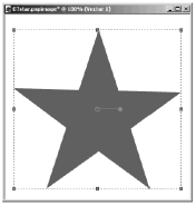
With the Preset Shapes tool set to Create as vector, draw a filled five-pointed star using Star 2 as your shape (see Figure 6.12). Be sure that in the Materials palette you have Stroke set to Transparent and Fill set to Solid Color , with a brown shade as the fill color.
Figure 6.12. A five-pointed vector star.
-
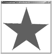
Choose the Pen tool, which should automatically be in Edit mode. In the image canvas, you'll see the nodes and segments of the star, as shown in Figure 6.13.
Figure 6.13. The star in Edit mode.
-
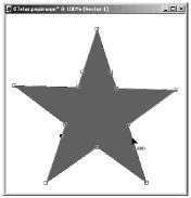
Now add a few more nodes to the star. To add a node, hold down the Ctrl key and click on the path of the star wherever you want a new node. Add two nodes for the neck, and add two more nodes for the points where the torso meets the legs, as shown in Figure 6.14.
Figure 6.14. Adding nodes for the neck and torso.
-
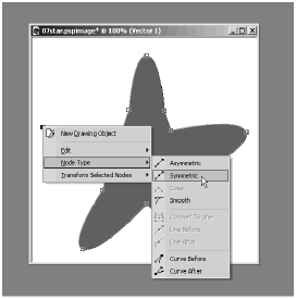
At this point, all of the nodes define straight line segments, but what you want instead is for the nodes for the head and the ends of the arms and legs to connect as smooth curves. To convert a node to a different type, select the node by clicking it or dragging a selection box around it with the Pen tool, and then right-click. In the context menu, select N ode Type > Symmetric. Notice how the line segments connected to the node then curve at the node. Repeat for each of the other nodes that you want to convert. Figure 6.15 shows how the shape is changed once all the nodes of the star are converted in this way.
Figure 6.15. Changing some of the lines to curves.
-
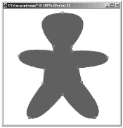
Now, fine-tune the curves of the head, arms, and legs. Click a node or drag around it to select it. A selected symmetric node displays an arrow-shaped control. Pull on the head or tail of the arrow to adjust the length of the segments connected to the node. Rotate the head or tail of the arrow to adjust the curvature of the path near the node. To move a node, click and drag the node. When you finish adjusting each of the nodes of the head, arms, and legs, the shape will look something like a gingerbread man (see Figure 6.16).
Figure 6.16. The completed gingerbread man shape.
-
Now let's add some texture to the gingerbread man:
-
Right-click the Star 2 object button in the Layers palette and choose Copy.
-
Right-click the Star 2 object button again and choose Paste New Vector Selection. You'll then see an outline of the copied gingerbread man shape. Drag this shape so that it lines up exactly with the original gingerbread man object.
-
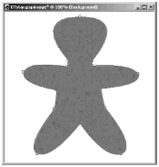
Double-click the object button for the copied Star 2 to bring up its Vector Property dialog box. In the dialog box, click the Fill color box to bring up the Materials dialog box. In the Color Picker, choose a brown that is slightly lighter than the original brown. Then select Texture and click the Texture preview to bring up the Texture Picker. Choose something that will produce a good texture for gingerbread, such as Asphalt 1. Click OK to exit the Materials dialog box, and click OK again to exit the Vector Property dialog box. Your gingerbread man will now look something like what you see in Figure 6.17.
Figure 6.17. Adding texture to the gingerbread man.
-
-
Use the Preset Shapes tool to add stroked , unfilled vector circles for the gingerbread man's eyes and buttons .
NOTE
 CAUTION
 There's a bug in Paint Shop Pro versions 8.0 and 8.01. In these versions, after changing the vector properties of a shape, you won't be able to draw a new shape on top of the existing shape. A workaround is to draw your new shape outside the old shape and then drag the new shape into place.
This bug has been fixed in version 8.10, which is available as a free update.
-
Add a nose and mouth. The nose can be added with the Preset Shapes tool set to Triangle. For the mouth, use the Pen tool. Enter Draw mode by clicking the Draw Mode icon in the Pen tool's Tool Options palette. For Segment Type , select Point to Point , and then draw like this:
-
Click where you want the left corner of the mouth. Be sure not to drag.
-
Click where you want the right corner of the mouth. Again, do not drag. You define straight lines with Point to Point by clicking at each endpoint of the line.
-
Click where you want the middle of the lower part of the mouth and this time drag a little. Dragging with Point to Point creates a node that defines a curve before and after it.
-
Click the Close selected open contours icon in the Pen tool's Tool Options palette. The mouth shape is then done.
-
And that's that. The gingerbread man is now complete. And all from a simple star.
Changing Node Types
In the previous section, node types were mentioned briefly . The nodes for a curve can be any of four basic types: asymmetric, symmetric, cusp, or smooth. An asymmetric node has control arms that control the length of the curves before and after the node independently of each other but that work in concert in determining the orientation of the curve before and after the node. A symmetric node has control arms that influence each other completelyadjust the length or direction of one and the other is adjusted as well. A cusp has control handles that are completely independent of each other; use a cusp node when you want to produce a sharp angle. A smooth node provides a smooth transition from a straight line to a curve.
To change a node's type, use the Pen tool in Edit mode. Select the node that you want to change, right-click in the image canvas, and in the context menu choose Node Type and the specific type that you want.
NOTE
 TIP
TIP
You can change several nodes at once to a specific type. Just select all the nodes that you want to change to that type, then right-click in the image canvas, and in the context menu choose the node type that you want.
An easy way to select all the nodes is to double-click one of the object's nodes.
Transforming Selected Nodes
The fifth segment of the Pen tool's Tool Options palette has some usefulbut easy to overlook options for transforming groups of nodes in an object. There's a drop-down list for Transformation Type, two Jasc Numeric Editors (JNEs) whose use is determined by the specific transformation type selected, and an Apply icon.
Here are the various transformation types and their settings:
-
Duplicate Selected. All the selected nodes are duplicated as a new contour.
-
Rotate. All the selected nodes are rotated .
-
Skew X. The shape defined by the selected nodes is skewed horizontally.
-
Skew Y. The shape defined by the selected nodes is skewed vertically.
-
Contract. Selected nodes are contracted. If only some nodes in the shape are selected, the control arms for those nodes are contracted. If all of the nodes defining a shape are selected, the entire shape shrinks.
-
Expand. Selected nodes are expanded. If only some nodes in the shape are selected, the control arms for those nodes are expanded. If all the nodes defining a shape are selected, the entire shape grows in size.
To apply a transformation, select Transformation Type, choose whatever settings you want for that transformation, and click the Apply button. You can reapply the same transformation with the same settings by clicking the Apply button again.
Experiment with transformations to see just what they can do. We'll be using some transformations in the example at the end of this chapter. You're sure to find many other uses for transformations, too.
NOTE
 TIP
TIP
All of the transformations except Duplicate Selected can also be accessed from the Transform Selected Nodes submenu of the Pen tool's context menu. This submenu also provides options for Flip and Mirror.
Making Cutouts with Vectors
Now let's see how to create an object with a cutout (a hole in the object). An example is shown in Figure 6.18.
Figure 6.18. A cutout effect created with vectors.
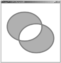
To create this effect, you take advantage of the direction of independent elements (or "contours") of a vector object. A contour is a set of connected nodes, and an object can have one or more contours.
The path of an object made with the Preset Shapes tool has a direction from its Start point to its Close point. For example, if you draw an ellipse by dragging from upper left to lower right, the path will have a clockwise direction. The direction of the path of a shape that you draw by hand depends on how you draw the shape: Proceed clockwise, and the path goes clockwise; proceed counterclockwise, and the path goes counterclockwise. The direction of a path is indicated by the arrow controls on a nodethe arrow points in the direction of the path, as shown in Figure 6.19.
Figure 6.19. A vector path has a direction.
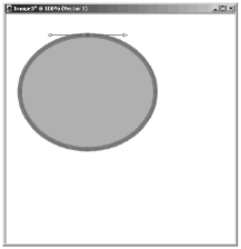
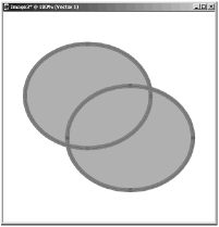
Now consider what happens when you have two independent contours in an object. Figure 6.20 shows an object made of the original shape shown in Figure 6.19 and a copy of that shape. (The copy was made by selecting all the nodes of the first shape with the Pen tool, then using Duplicate Selected in the Pen tool's Tool Options palette, with Duplicate X and Duplicate Y both set to 100.)
Figure 6.20. An object with two contours.
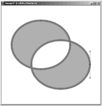
Now let's make the cutout. In the Pen tool's Edit mode, deselect all the nodes by right-clicking and choosing E dit > Select None (or simply click anywhere in the image canvas except on one of the object's nodes or edges). Then select a single node on one of the contours by clicking that node or dragging a selection box around the node with the Pen tool. Right-click to bring up the context menu, and select E dit > Reverse Contour (or instead of using the menu, just press Ctrl+R). You'll see that the arrow control has switched to indicate counterclockwise direction for the contour the node is on (see Figure 6.21).
Figure 6.21. Reversing the contour.
After you deselect the object, you'll see something like what you saw in Figure 6.18.
At the point where the two contours overlap, the intersection is treated as being "outside" the object. In this example, the contours partially overlap, so each contour produces solid areas (where they don't overlap) and a hole (where they do overlap). If one contour is entirely contained in the other, what you get is a continuous object that looks like it has a hole in the middle.
NOTE
 NOTE
NOTE
If you're trying to make a cutout with vectors but no cutout appears, it may be that you accidentally chose Reverse Path instead of Reverse Contour. Reverse Path reverses the path direction for all contours of an object. Reverse Contour reverses the path direction of only the contour that contains the currently selected node.
To get the cutout, first be sure that you have only one node selected. Then try Reverse Contour again: Right-click to bring up the context menu, and choose E dit > Reverse Contour.
| [ LiB ] |