Internet Control Message Protocol (ICMP)
Overview
IP provides end-to-end datagram delivery capabilities for IP datagrams. However, IP does not provide any facilities for reporting routing or delivery errors encountered by anIP datagram in its journey from the source to the destination. The Internet Control Message Protocol (ICMP) reports error and control conditions on behalf of IP.
When a protocol encounters an error that cannot be recovered in the processing of a packet, it can do one of the following:
- Discard the offending packet without sending an error notification to thesending host. This is known as a silent discard. For example, an Ethernetnetwork adapter checks each Ethernet frame for bit-level errors by performing a checksum and comparing its own result with the Frame Check Sequence value stored in the frame. If the two checksums do not match, the adapterconsiders the frame invalid and silently discards it.
- Discard the offending packet and send an error notification to the sending host. This is known as an informed discard. ICMP provides an informed discard service for specific types of IP routing and delivery errors.
ICMP is an extensible protocol that also provides functions to check IP connectivity and aid in the automatic configuration of hosts.
ICMP does not make IP reliable. There are no facilities within IP or ICMP to provide sequencing or retransmission of IP datagrams that encounter errors. ICMP messages are unreliably sent as IP datagrams, and although ICMP reports an error, there are no requirements for how the sending host treats the error. It is up to the TCP/IP implementation to interpret the error and adjust its behavior accordingly.
ICMP messages are sent only for the first fragment of an IP datagram. ICMP messages are not sent for problems encountered by ICMP error messages or for problems encountered by broadcast or multicast datagrams.
| More Info |
ICMP is documented in RFCs 792, 950, 1812, 1122, 1191, and 1256. These RFCs can be found in the Rfc folder on the companion CD-ROM. |
ICMP Message Structure
ICMP messages are sent as IP datagrams. Therefore, an ICMP message consisting of an ICMP header and ICMP message data is encapsulated with an IP header using IP Protocol number 1. The resulting IP datagram is then encapsulated with the appropriate Network Interface Layer header and trailer. Figure 8-1 shows the resulting frame.
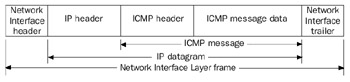
Figure 8-1: ICMP message encapsulation showing the IP header and Network Interface Layer header and trailer.
In the IP header of ICMP messages, the Source IP Address field is set to the router or host interface that sent the ICMP message. The Destination IP Address field is set to the sending host of the offending packet (in the case of ICMP error messages), a specific host, anIP broadcast, or IP multicast address. Every ICMP message has the same structure, as Figure 8-2 shows.
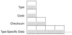
Figure 8-2: The structure of an ICMP message showing the fields common to all types of ICMP messages.
The common fields in the ICMP message are defined as follows:
- TypeA 1-byte field that indicates the type of ICMP message (Echo vs. Echo Reply, and so on). Table 8-1 lists the most commonly used ICMP types.
- CodeA 1-byte field that indicates a specific ICMP message within an ICMP message type. If there is only one ICMP message within an ICMP type, the Code field is set to 0. The combination of ICMP Type and Code determines a specific ICMP message.
- ChecksumA 2-byte field for a 16-bit checksum covering the ICMP message. ICMP uses the same checksum algorithm as IP for the IP header checksum.
- Type-Specific DataOptional data for each ICMP type.
ICMP Messages
Table 8-1 lists the most commonly used ICMP types.
|
ICMP Type |
Description |
|---|---|
|
0 |
Echo Reply |
|
3 |
Destination Unreachable |
|
4 |
Source Quench |
|
5 |
Redirect |
|
8 |
Echo (also known as an Echo Request) |
|
9 |
Router Advertisement |
|
10 |
Router Solicitation |
|
11 |
Time Exceeded |
|
12 |
Parameter Problem |
| More Info |
For a complete list of ICMP types, see http://www.iana.org/assignments/icmp-parameters. |
The following sections discuss the ICMP messages supported by TCP/IP for the Microsoft Windows Server 2003 family.
ICMP Echo and Echo Reply
One of the most heavily used ICMP facilities is the ability to send a simple message to an IP node and have the message echoed back to the sender. This facility is useful for network troubleshooting and debugging. The simple message sent is an ICMP Echo, and the message echoed back to the sender is an ICMP Echo Reply. For the Windows Server 2003 family, the Ping, Tracert, and Pathping utilities use Echo and Echo Reply messages to provide information about reachability and the path taken to reach a destination node. Figure 8-3 shows the ICMP Echo message structure.
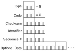
Figure 8-3: The structure of the ICMP Echo message.
The fields in the ICMP Echo message are defined as follows:
- TypeSet to 8.
- CodeSet to 0.
- IdentifierA 2-byte field that stores a number generated by the sender that is used to match the ICMP Echo with its corresponding Echo Reply.
- Sequence NumberA 2-byte field that stores an additional number that is used to match the ICMP Echo with its corresponding Echo Reply. The combination of the values of the Identifier and Sequence Number fields identifies a specific Echo message.
- Optional DataOptionally, data can be added at the end of the ICMP packet.
For information on how the Windows Server 2003 family determines Identifier,Sequence Number, and Optional Data fields, see the sections "Ping Utility" and "Tracert Utility," later in this chapter.
Frame 1 of the Network Monitor Capture 08-01 (in the Captures folder on the companion CD-ROM) shows the structure of an ICMP Echo message.
Figure 8-4 shows the ICMP Echo Reply message structure.
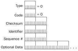
Figure 8-4: The structure of the ICMP Echo Reply message.
The fields in the ICMP Echo Reply message are defined as follows:
- TypeSet to 0.
- CodeSet to 0.
- IdentifierSet to the value of the Identifier field of the Echo message being echoed.
- Sequence NumberSet to the value of the Sequence Number field of the Echo message being echoed.
- Optional DataSet to the value of the Optional Data field of the Echo message being echoed.
Echoed in the Echo Reply message are the Identifier, Sequence Number, and Optional Data fields. The host that sent the original Echo message verifies these fields on receipt. If the fields are not correctly echoed, the Echo Reply message is ignored.
Frame 2 of the Network Monitor Capture 08-01 (in the Captures folder on the companion CD-ROM) shows the structure of an ICMP Echo Reply message sent in response to an Echo message.
Sending ICMP Echo messages and receiving ICMP Echo Reply messages checks for the following:
- The host sending the Echo message can forward the Echo message to either the destination (direct delivery) or to a neighboring router (indirect delivery).
- The routing infrastructure between the host sending the Echo message and the destination can forward the Echo message to the destination.
- The host sending the Echo Reply message can forward the Echo Reply message to either the destination (the sender of the Echo message) or to a neighboring router.
- The routing infrastructure between the host sending the Echo Reply message and the destination can forward the Echo Reply message to the destination.
ICMP Destination Unreachable
IP attempts a best-effort delivery of datagrams to their destination. Routing or delivery errors can occur along the path or at the destination. When a routing or delivery error occurs, a router or the destination discards the offending datagram and attempts to report the error by sending an ICMP Destination Unreachable message to the source IP address of the offending packet. Figure 8-5 shows the ICMP Destination Unreachable message structure.
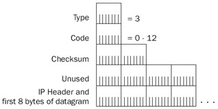
Figure 8-5: The structure of the ICMP Destination Unreachable message.
The fields in the ICMP Destination Unreachable message are defined as follows:
- TypeSet to 3.
- CodeSet to a value from 0 to 13. Table 8-2 lists and discusses the different ICMP Destination Unreachable Code values.
- IP Header + First 8 Bytes Of Offending DatagramTo provide meaningful information to the sender of the offending datagram, the ICMP DestinationUnreachable message contains the IP header and the first 8 bytes of the discarded datagram. The IP header contains the IP Identification field. For Transmission Control Protocol (TCP) segments, the first 8 bytes of the IP payload contain the source and destination port numbers and the sequence number. For User Datagram Protocol (UDP) messages, the first 8 bytes contain theentire UDP header including the source and destination port numbers.
Table 8-2: Code Values for ICMP Destination Unreachable Messages Code Value
Meaning
0 - Network Unreachable
Sent by an IP router when a route for the destination IP address cannot be found in the routing table. The source IP address of this message identifies the router that could not find a route. This message is largely obsolete in today's classless Internet due to the inability of the router to determine the network ID of the destination.
1 - Host Unreachable
Sent by an IP router when a route to the destination was not found in the routing table. In today's classless Internet, this is the more appropriate message to send when a router cannot determine the next hop for an IP datagram. This message's source IP address identifies the router that could not deliver the datagram to the destination host.
2 - Protocol Unreachable
Sent by the destination host when the Protocol field in the data- gram's IP header does not match a client protocol of IP that isbeing used by the destination. For example, if a host is sent an Open Shortest Path First (OSPF) packet (IP protocol 89), it sendsa Protocol Unreachable message back to the sender.
3 - Port Unreachable
Sent by the destination host when the destination port in the UDP or TCP header does not match an application running on the destination. In practice, however, when TCP ports cannot be found, TCP sends a Connection Reset segment. Therefore, Port Unreachable messages are sent only for UDP messages.
4 - Fragmentation Needed And DF Set
Sent by an IP router when fragmentation is needed to forward the IP datagram but the Don't Fragment (DF) flag is set in the IP header. The Fragmentation Needed And DF Set message is an important part of the Path Maximum Transmission Unit (PMTU) Discovery process discussed in the "PMTU Discovery" section of this chapter. This message's source IP address identifies the router that could not fragment the IP datagram.
5 - Source Route Failed
Sent by an IP router when it cannot forward an IP datagram using information stored in the Source Route option in the IP header. For example, this ICMP Destination Unreachable message is sent if the sending host is using a strict source route and the next router is not directly reachable. The Source Route Failed message contains source route options of the same type as the offending datagram and includes the path back to the sending host. This message's source IP address identifies the router that could not forward the source-routed IP datagram. For more information on IP source routing, see Chapter 5, "Internet Protocol (IP) Basics."
6 - Destination
Sent by an IP router when the destination network for the destination Network Unknown IP address is indicated in the routing table as an unknown network. In practice, the Destination Network Unknown message is obsolete; IP routers send a Host Unreachable message instead.
7 - Destination
Sent by an IP router when the destination host does not exist asHost Unknown detected through Network Interface Layer mechanisms. In practice, the Destination Host Unknown message is sent only when the router cannot deliver to a host that is connected to the router by a point- to-point link. This message's source IP address identifies the router that could not deliver the IP datagram.
8 - Source Host Isolated
An obsolete message sent by an IP router when it can detect that the source host is isolated from the rest of the network.
9 - Communication
Sent by an IP router when a route to the destination IP address waswith Destination found but the router cannot forward the IP datagram because of aNetwork Administra- prohibitive network policy. This message's source IP address identi-tively Prohibited fies the router that could not forward the IP datagram.
10 - Communication
Sent by an IP router when it cannot deliver to the destination hostwith Destination Host because of a prohibitive network policy. This message's source IPAdministratively address identifies the router that could not deliver the IP datagram.Prohibited
11 - Network
Sent by an IP router when a route to the destination IP address forUnreachable the Type Of Service (TOS) indicated in the IP header of the IPfor Type of Service datagram was not found. Only routers that use the TOS field when forwarding IP datagrams send this message. This message's sourceIP address identifies the router that could not forward the IP datagram.
12 - Host
Sent by an IP router when it cannot deliver to the destination host forUnreachable the TOS indicated in the IP header of the IP datagram. Only routersfor Type of Service that use the TOS field when forwarding IP datagrams send this message. This message's source IP address identifies the router that could not forward the IP datagram.
13 - Communication
Sent by an IP router when it cannot forward or deliver the IPAdministratively datagram because of administratively configured packet filters on theProhibited Because router. This message's source IP address identifies the router that of Firewalls could not forward or deliver the IP datagram.
Network Monitor Example
To illustrate a Destination Unreachable message, examine the following Network Monitor trace (Capture 08-02 in the Captures folder on the companion CD-ROM). Frame 1 is an Echo message sent to a private address while on the Internet. Because private addresses are not reachable on the Internet, Frame 2 is the ICMP Destination Unreachable-Host Unreachable message sent by an Internet router.
Frame 1: The ICMP Echo Message
+ FRAME: Base frame properties
+ ETHERNET: ETYPE = 0x0800 : Protocol = IP: DOD Internet Protocol
IP: ID = 0x8A03; Proto = ICMP; Len: 60
 IP: Version = 4 (0x4)
 IP: Header Length = 20 (0x14)
 IP: Precedence = Routine
 IP: Type of Service = Normal Service
 IP: Total Length = 60 (0x3C)
 IP: Identification = 35331 (0x8A03)
 + IP: Flags Summary = 0 (0x0)
 IP: Fragment Offset = 0 (0x0) bytes
 IP: Time to Live = 32 (0x20)
 IP: Protocol = ICMP - Internet Control Message
 IP: Checksum = 0x26AA
 IP: Source Address = 134.39.89.236
 IP: Destination Address = 10.0.0.1
 IP: Data: Number of data bytes remaining = 40 (0x0028)
 ICMP: Echo: From 134.39.89.236 To 10.00.00.01
 ICMP: Packet Type = Echo
 ICMP: Echo Code = 0(0x0)
 ICMP: Checksum = 0x1B5C
 ICMP: Identifier = 256 (0x100)
 ICMP: Sequence Number = 12544 (0x3100)
 ICMP: Data: Number of data bytes remaining = 32 (0x0020)
Frame 2: The ICMP Destination Unreachable-Host Unreachable Message
+ FRAME: Base frame properties
+ ETHERNET: ETYPE = 0x0800 : Protocol = IP: DOD Internet Protocol
 IP: ID = 0x7AA9; Proto = ICMP; Len: 56
 IP: Version = 4 (0x4)
 IP: Header Length = 20 (0x14)
 IP: Precedence = Routine
 IP: Type of Service = Normal Service
 IP: Total Length = 56 (0x38)
 IP: Identification = 31401 (0x7AA9)
 + IP: Flags Summary = 0 (0x0)
 IP: Fragment Offset = 0 (0x0) bytes
 IP: Time to Live = 252 (0xFC)
 IP: Protocol = ICMP - Internet Control Message
 IP: Checksum = 0xBA4A
 IP: Source Address = 168.156.1.33
 IP: Destination Address = 134.39.89.236
 IP: Data: Number of data bytes remaining = 36 (0x0024)
 ICMP: Destination Unreachable: 10.0.0.1 (See frame 1)
 ICMP: Packet Type = Destination Unreachable
 ICMP: Unreachable Code = Host Unreachable
 ICMP: Checksum = 0xA7A2
 ICMP: Unused Bytes = 0 (0x0)
 ICMP: Data: Number of data bytes remaining = 28 (0x001C)
 ICMP: Description of original IP frame
 ICMP: (IP) Version = 4 (0x4)
 ICMP: (IP) Header Length = 20 (0x14)
 + ICMP: (IP) Service Type = 0 (0x0)
 ICMP: (IP) Total Length = 60 (0x3C)
 ICMP: (IP) Identification = 35331 (0x8A03)
 + ICMP: (IP) Flags Summary = 0 (0x0)
 ICMP: (IP) Fragment Offset = 0 (0x0) bytes
 ICMP: (IP) Time to Live = 28 (0x1C)
 ICMP: (IP) Protocol = ICMP - Internet Control Message
 ICMP: (IP) Checksum = 0x2AAA
 ICMP: (IP) Source Address = 134.39.89.236
 ICMP: (IP) Destination Address = 10.0.0.1
 ICMP: (IP) Data: Number of data bytes remaining = 8 (0x0008)
 ICMP: Description of original ICMP frame
 ICMP: Checksum = 0x1B5C
 ICMP: Identifier = 256 (0x100)
 ICMP: Sequence Number = 12544 (0x3100)
Notice that the ICMP Destination Unreachable-Host Unreachable message contains the discarded version of the IP header and the first 8 bytes (the ICMP header) of Frame 1.
PMTU Discovery
As discussed in Chapter 5, "Internet Protocol Basics," IP fragmentation is an expensive process for both routers and the destination host and should be avoided. An early solution to avoiding fragmentation was the use of a 576-byte IP maximum transmission unit (MTU) to send data to a location on another network. RFC 791 recommends that Network Interface Layer technologies support an IP MTU size of 576 bytes. However, this solution is inefficient; two Ethernet nodes separated by routers send each other 576-byte IP datagrams rather than 1500-byte IP datagrams.
The current solution to avoiding fragmentation is known as PMTU Discovery, and is described in RFC 1191. With PMTU Discovery, hosts send all IP datagrams with the DF flag set to 1. If a router cannot forward an IP datagram onto a link because the datagram's size exceeds the link's MTU, it sends an ICMP Destination Unreachable-Fragmentation Needed And DF Set message (ICMP Type 3, Code 4) back to the sender. Although this has been the behavior since the inception of IP and ICMP, PMTU Discovery support on the router modifies the ICMP message to include the IP MTU of the link onto which the forwarding of the IP datagram failed.
Figure 8-6 shows the modified ICMP Destination Unreachable message. The previous 32-bit Unused field is now a 16-bit Unused field and a 16-bit Next Hop MTU field. The router sets the Next Hop MTU field to the next-hop network segment's IP MTU. After receiving this message, the sending host adjusts the size of the IP datagram to the Next Hop MTU size and retransmits the IP datagram. Sending hosts and all the IP routers in your internetwork must support PMTU.
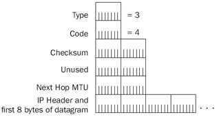
Figure 8-6: A PMTU-compliant ICMP Destination Unreachable-Fragmentation Needed And DF Set message showing the Next Hop MTU field.
To discover the initial PMTU, a sending host that supports PMTU sets the initial PMTU to the IP MTU of the directly attached network. The host then sends an IP datagram with the DF flag set to 1 at the PMTU size.
After receipt of an ICMP Destination Unreachable-Fragmentation Needed And DF Set message with the Next Hop MTU indicated, the sending host sets the PMTU to the value of the Next Hop MTU and resends the adjusted IP datagram.
The PMTU is determined when no more ICMP Destination Unreachable-Fragmentation Needed And DF Set messages are received.
In the Network Monitor Capture 08-03 (in the Captures folder on the companion CD-ROM), Frame 1 shows an ICMP Echo message with the DF set to 1 and a 1000-byte Optional Data field. This packet is being forwarded across a router interface that supports only a 576-byte IP MTU. Frame 2 is an ICMP Destination Unreachable-Fragmentation Needed And DF Set message indicating the Next Hop MTU of 576.
Adjusting the PMTU
In a single-path internetwork, the PMTU remains the same once discovered. In a multipath internetwork, the PMTU can change based on the paths that the IP datagrams travel because of changing conditions in the routing infrastructure. The PMTU can change to be either higher or lower than the currently known PMTU.
- For a lower PMTU, the sending host is immediately informed through a Destination Unreachable-Fragmentation Needed And DF Set message.
- For a higher PMTU, because there is no mechanism on the routers to inform the sending host that larger datagrams can now be sent, it is up to the host to rediscover the new larger PMTU. If the host's PMTU is smaller than the IP MTU of the locally attached network, the sending host attempts to send larger IP datagrams five minutes after receiving the last ICMP Destination Unreachable-Fragmentation Needed And DF Set message, and at one-minute intervals thereafter.
Routers That Do Not Support PMTU
PMTU Discovery relies on PMTU support on the sending host and all of the internetwork's routers. TCP/IP for the Windows Server 2003 family supports PMTU Discovery for both hosts and routers. However, what happens when an intermediate router does not support PMTU Discovery?
The lack of support for PMTU Discovery on IP routers can occur on the following two levels:
- The router sends back ICMP Destination Unreachable-Fragmentation Needed And DF Set messages without the Next Hop MTU field.
- The router does not send back ICMP Destination Unreachable-Fragmentation Needed And DF Set messages.
In the first case, the router is not RFC 1191–compliant and according to the sending host, the Destination Unreachable-Fragmentation Needed And DF Set message contains a 0 Next Hop MTU. The sending host assumes that PMTU Discovery is not possible and uses either the minimum PMTU of 576 bytes or a series of plateau values for the PMTU until Destination Unreachable-Fragmentation Needed And DF Set messages are no longer received. Table 8-3 lists the plateau values, which correspond to the IP MTUs of common Network InterfaceLayer technologies. Hosts running a member of the Windows Server 2003 family do not use these plateau values. TCP/IP PMTU behavior for the Windows Server 2003 family is described later in this chapter.
|
Plateau Value |
Representing |
|---|---|
|
65,535 |
Maximum IP MTU |
|
32,000 |
Just in case |
|
17,914 |
16-Mbps IBM Token Ring |
|
8166 |
IEEE 802.4 |
|
4352 |
IEEE 802.5 (4 Mbps) and Fiber Distributed Data Interface (FDDI) |
|
2002 |
Wideband Network and IEEE 802.5 (4 Mbps) |
|
1492 |
Ethernet/IEEE 802.3 (Sub-Network Access Protocol [SNAP]) |
|
1006 |
Serial Line Internet Protocol (SLIP) |
|
508 |
X.25 and Attached Resource Computer Network (ARCnet) |
|
296 |
Point-to-Point (low delay) |
|
68 |
Minimum IP MTU |
When a router does not send back Destination Unreachable-Fragmentation Needed And DF Set messages, it is called a PMTU Black Hole Router. PMTU Black Hole Routers perform silent discards for datagrams that cannot be fragmented. Because IP is unreliable, it is the responsibility of an upper layer protocol to recover from the discarded packet. For example, TCP segments are retransmitted when their retransmission timer expires.
To successfully detect a PMTU Black Hole Router, discarded packets with the DF flag set to 1 are retransmitted with the DF flag set to 0. If an acknowledgment is received, the TCP maximum segment size (MSS) is lowered to the next lowest plateau value and the DF flag for subsequent IP datagrams is set to 1. This process repeats until the PMTU is found.
TCP/IP PMTU behavior for the Windows Server 2003 family is controlled by the following registry settings:
EnablePMTUBHDetect
Location:
HKEY_LOCAL_MACHINESYSTEMCurrentControlSetServicesTcpipParameters
Data type: REG_DWORD
Valid range: 0-1
Default: 0
Present by default: No
EnablePMTUBHDetect enables (when set to 1) or disables (when set to 0) the detection of PMTU Black Hole Routers. By default, detection of PMTU Black Hole Routers is disabled. TCP sends segments with the DF flag set to 1. If no acknowledgments are received after the maximum number of TCP retransmissions, the TCP connection is terminated. If enabled, thePMTU is set at 576 bytes after no acknowledgment is received for a large segment after several retransmissions.
EnablePMTUDiscovery
Location:
HKEY_LOCAL_MACHINESYSTEMCurrentControlSetServicesTcpipParameters
Data type: REG_DWORD
Valid range: 0-1
Default: 1
Present by default: No
EnablePMTUDiscovery enables (when set to 1) or disables (when set to 0) PMTU Discovery for TCP connection data. By default, PMTU Discovery is enabled. TCP attempts to discover the PMTU by initially transmitting segments at the largest segment size and then adjusting the segment size when Destination Unreachable-Fragmentation Needed And DF Set messages are received.
If disabled, PMTU Discovery is not performed and an IP MTU of 576 bytes is assumed for traffic not destined to a host on a locally attached network.
ICMP Source Quench
When a router becomes congested because of a sudden increase in traffic, a slow link, or inadequate processor and memory resources, the router begins to discard incoming IP datagrams. When a router discards an IP datagram because of congestion, it might send an ICMP Source Quench message back to the sending host. The Source IP Address field of the ICMP Source Quench message identifies the congested router. The destination host can also send ICMP Source Quench messages when IP datagrams are arriving too quickly to be buffered.
RFC 792 does not document the specific implementation details of when a router or destination host sends ICMP Source Quench messages. A router can begin sending Source Quench messages when its memory buffer for storing incoming packets is approaching its maximum capacity, rather than waiting for the buffer to fill. A router does not have to send a Source Quench message for every packet discarded. In fact, RFC 1812 states that routers should not send ICMP Source Quench messages because creating more traffic on a congested internetwork only aggravates the congestion.
The ICMP Source Quench message is an Internet Layer notification. However, the Internet Layer has no mechanism for flow control. IP is unaware of when to increase or decrease its transmission rate. Similarly, UDP has no mechanism for flow control.
TCP is an upper layer protocol that has flow control mechanisms to lower the transmission rate. Therefore, after receipt of the ICMP Source Quench message for a discarded TCP segment, a notification is made to TCP. TCP treats the receipt of the ICMP Source Quenchmessage for a specific TCP segment as a lost TCP segment that needs to be retransmitted. TCP then adjusts its transmission rate for the connection according to the slow start and congestion avoidance algorithms. The sending host gradually increases its transmission rate, giving time for the routers to clear their buffers. For more information, see Chapter 14, "Transmission Control Protocol (TCP) Data Flow." Figure 8-7 shows the ICMP Source Quench message structure.
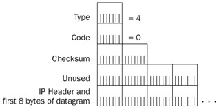
Figure 8-7: The structure of the ICMP Source Quench message.
The fields in the ICMP Source Quench message are defined as follows:
- TypeSet to 4.
- CodeSet to 0.
- IP Header + First 8 Bytes Of Discarded DatagramThe ICMP Source Quench message contains the IP header and the first 8 bytes of the discarded datagram.
In the Windows Server 2003 family, TCP/IP properly implements TCP flow control if an ICMP Source Quench message is received and contains the IP header and TCP header (only the first 8 bytes) for an active TCP connection. In the Windows Server 2003 family, TCP/IP does not send ICMP Source Quench messages as a router when the router buffers fill and packets are discarded.
ICMP Redirect
It is common for hosts to have minimal routing tables. A typical host has a route to the locally attached network and a default route corresponding to the host's configured default gateway. The routers keep all other knowledge of the internetwork's topology—the entire list of network IDs and the best next-hop IP addresses to reach them. For network segments containing a single router and hosts configured with the IP address of the single router as their default gateway, all routing from hosts to remote networks occurs through the optimal path—the single router.
However, if there are multiple routers on a network segment with hosts configured with a default gateway of a single router, the possibility exists for nonoptimal routing. Consider the IP internetwork in Figure 8-8.
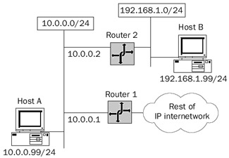
Figure 8-8: An ICMP Redirect scenario where a host with a configured default gateway must forward an IP datagram using another router.
Host A, 10.0.0.99/24, is configured with the default gateway of 10.0.0.1. Host A sends an IP datagram to Host B at 192.168.1.99. Router 1 is attached to network 10.0.0.0/24 and the rest of the IP internetwork. Router 2 is attached to network 10.0.0.0/24 and 192.168.1.0/24. According to the default route in Host A's IP routing table, to reach 192.168.1.99, forward the IP datagram to 10.0.0.1. This is not the optimal path, however. For the optimal path, the datagram must be forwarded to 10.0.0.2.
To inform Host A of the more optimal route for traffic to Host B at 192.168.1.99, Router 1 uses an ICMP Redirect message. Host A uses the contents of the ICMP Redirect message to create a host route in its routing table so that subsequent IP datagrams to Host B take the more optimal route through Router 2 at 10.0.0.2.
The following is the ICMP Redirect process in detail:
- Host A forwards the IP datagram destined for Host B to its default gateway, Router 1, at the IP address of 10.0.0.1.
- Router 1 receives the IP datagram. Because the IP datagram is not destined for an IP address assigned to Router 1, Router 1 checks the contents of its routing table for a route to Host B. A route is found for 192.168.1.0/24 at the next-hop IP address of 10.0.0.2.
- Before forwarding the IP datagram to Router 2 at 10.0.0.2, Router 1 notices that the sending host's IP address, the IP address of the interface on which the IP datagram was received, and the next-hop IP address are all on the same network, 10.0.0.0/24.
- Router 1 forwards the IP datagram to Router 2.
- Router 1 sends an ICMP Redirect message to Host A. The Redirect message contains the next-hop IP address for Router 2, 10.0.0.2, and the IP header of the discarded IP datagram.
- Based on the contents of the Redirect message, Host A creates a host route for the IP address of Host B, 192.168.1.99, at the next-hop IP address of 10.0.0.2.
- Subsequent packets from Host A to Host B are forwarded to Router 2 at theIP address of 10.0.0.2.
ICMP Redirect messages are never sent for IP datagrams using source route options. The presence of source route options means that a specific path must be followed without regard to whether it is optimal. Source route options are sometimes used to testconnectivity along nonoptimal paths.
Figure 8-9 shows the ICMP Redirect message structure.
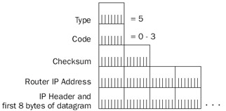
Figure 8-9: The structure of the ICMP Redirect message.
The fields in the ICMP Redirect message are defined as follows:
- TypeSet to 5.
- CodeSet to 0–3 (see Table 8-4).
Table 8-4: Values of the Code Field in an ICMP Redirect Code Value
Meaning
0
Redirected datagrams for the network (obsolete)
1
Redirected datagrams for the host
2
Redirected datagrams for the TOS and the network
3
Redirected datagrams for the TOS and the host
- Router IP AddressA 4-byte field set to the next-hop IP address for the more optimal route to the destination of the offending IP datagram. This IP address becomes the address in the Gateway column of the host route created in theIP routing table for the Windows Server 2003 family.
- IP Header + First 8 Bytes Of Forwarded DatagramTo identify the forwarded IP datagram, the IP header and the first 8 bytes of the IP payload are encapsulated and sent back to the sending host. Included in the encapsulated IP header is the destination IP address that becomes the value in the Destination Network column for the host route created in the IP routing table for the Windows Server 2003 family. The Network Mask for the host route is set to 255.255.255.255.
Note ICMP Redirect messages are sent only when the sending host forwards an IP datagram using a nonoptimal route. ICMP Redirect messages are never sent when routers forward IP datagrams using nonoptimal routes.
Network Monitor Capture 08-04 (in the Captures folder on the companion CD-ROM) shows an ICMP Echo message and the ICMP Redirect message for the example previously discussed.
In the Windows Server 2003 family, TCP/IP behavior for ICMP Redirect messages is controlled by the following registry setting:
EnableICMPRedirect
Location:
HKEY_LOCAL_MACHINESYSTEMCurrentControlSetServicesTcpipParameters
Data type: REG_DWORD
Valid range: 0-1
Default: 0
Present by default: Yes
EnableICMPRedirect enables (when set to 1) and disables (when set to 0) the adding of host routes to the IP routing table when an ICMP Redirect message is received. EnableICMPRedirect is disabled by default. If enabled, when a host running TCP/IP for the Windows Server 2003 family receives an ICMP Redirect message, it first checks the source IP address to ensure that it was sent from the router indicated by the Gateway column for the route to the destination in the IP routing table. TCP/IP for the Windows Server 2003 family also ensures that the source IP address of the ICMP Redirect is directly reachable. If the ICMP Redirect did not come from the directly reachable indicated router, the ICMP Redirect is ignored. Host routes created through ICMP Redirect messages persist in the routing table for 10 minutes. After 10 minutes, the ICMP Redirect process occurs again.
ICMP Router Discovery
ICMP Router Discovery is a set of ICMP messages documented in RFC 1256 that are used by both routers to advertise their presence and by hosts to discover their network segment's routers, and choose which router will be the host's default gateway. ICMP Router Discovery provides a fault-tolerance mechanism for downed routers. Hosts eventually realize that their current default gateway has become unavailable and switch their default gateway to the next most preferred router.
ICMP Router Discovery uses the following two different ICMP messages:
- ICMP Router AdvertisementThe ICMP Router Advertisement message is sent pseudo-periodically (at a random interval between a minimum and maximum value) by a router to advertise its continued existence, a preference level, and a time after which it can be considered unavailable.
- ICMP Router SolicitationHosts send an ICMP Router Solicitation message whenever they need to discover the most preferred router to use as their default gateway. ICMP Router Discovery–capable hosts that have not been configured with a default gateway send an ICMP Router Solicitation message on startup. Additionally, hosts send an ICMP Router Solicitation message when the availability time of their current default gateway (discovered through ICMP Router Discovery) expires.
ICMP Router Discovery is not a routing protocol; it provides information only on a preferred default gateway for hosts on a network segment. ICMP Router Discovery does not provide any information on network IDs or optimal paths.
ICMP Router Advertisement
Routers send the ICMP Router Advertisement message to either the all-hosts multicastIP address (224.0.0.1), the subnet (or network) broadcast address, or the limited broadcast address. ICMP Router Advertisements are sent pseudo-periodically and in response to an ICMP Router Solicitation. The default interval for ICMP Router Advertisements isbetween 7 and 10 minutes. The Routing and Remote Access service implementation of ICMP Router Discovery sends ICMP Router Advertisements to the all-hosts multicastIP address. Figure 8-10 shows the ICMP Router Advertisement message structure.
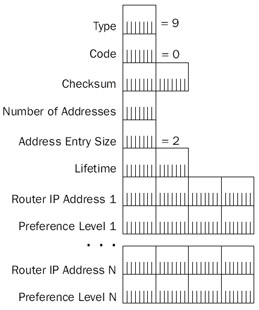
Figure 8-10: The structure of the ICMP Router Advertisement message.
The fields in the ICMP Router Advertisement message are defined as follows:
- TypeSet to 9.
- CodeSet to 0.
- Number Of AddressesA 1-byte field that indicates how many IP addresses are being advertised. Normally, only a single IP address is advertised. For a router with multiple interfaces on the same network segment, multiple IP addresses are advertised.
- Address Entry SizeA 1-byte field that indicates how many 32-bit words (4-byte quantities) are contained in a Router Advertisement entry. A Router Advertisement entry consists of an IP address (32 bits) and a preference level (32 bits). Therefore, the Address Entry Size field is always set to 2.
- LifetimeA 2-byte field that indicates the time in seconds after the last received Router Advertisement that the router can be considered down. This is equivalent to the Dead Interval for the OSPF routing protocol. The Lifetime field has a default value of 3600 (30 minutes).
- Router AddressA 4-byte field that indicates the IP address of the network segment's router interface on which the advertisement was sent.
- Preference LevelA 4-byte field that indicates the level of preference for using the Router Address as the IP address of your default gateway. The router advertising the highest preference level is the most preferred router. If there are two or more routers with the same preference level, the router with the numerically smallest router address becomes the default gateway. Router Advertisement behavior for the Routing and Remote Access service is configured per interface through the properties of an interface in the IP RoutingGeneral node in the Routing and Remote Access administrative tool.
ICMP Router Solicitation
Hosts send the ICMP Router Solicitation message to the all-routers multicast IP address (224.0.0.2), the subnet (or network) broadcast address, or the limited broadcast address.
TCP/IP for the Windows Server 2003 family listens for ICMP Router Advertisements that are sent to the all-hosts multicast address of 224.0.0.1 and sends up to three ICMP Router Solicitation messages spaced 600 milliseconds apart to the all-routers multicast IP address. Figure 8-11 shows the ICMP Router Solicitation message structure.
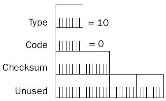
Figure 8-11: The structure of the ICMP Router Solicitation message.
The fields in the ICMP Router Solicitation message are defined as follows:
- TypeSet to 10.
- CodeSet to 0.
- ReservedA 4-byte field that is set to all 0s.
In the Windows Server 2003 family, TCP/IP host Router Discovery behavior is controlled by the following registry settings:
PerformRouterDiscovery
Location: HKEY_LOCAL_MACHINESYSTEMCurrentControlSetServices
TcpipParametersInterfacesInterfaceGUID
Data type: REG_DWORD
Valid range: 0-2
Default: 2
Present by default: No
PerformRouterDiscovery enables (when set to 1) and disables (when set to 0) ICMP Router Discovery per interface. Alternately, when PerformRouterDiscovery is set to 2 (the default), it is disabled but can be enabled if the computer is a Dynamic Host Configuration Protocol (DHCP) client and the Perform router discovery option (option code 31) is sent by the DHCP server.
SolicitationAddressBCast
Location: HKEY_LOCAL_MACHINESYSTEMCurrentControlSetServices
TcpipParametersInterfacesInterfaceGUID
Data type: REG_DWORD
Valid range: 0-1
Default: 0 (disabled)
Present by default: No
SolicitationAddressBCast enables (when set to 1) or disables (when set to 0) the use of the subnet (or network) broadcast address as the destination IP address of ICMP Router Solicitation messages. When disabled (the default), TCP/IP for the Windows Server 2003 family uses the all-routers IP multicast address (224.0.0.2).
ICMP Time Exceeded
The ICMP Time Exceeded message is sent in the following instances:
- When a router decrements the IP header's TTL field to 0 (the ICMP TimeExceeded-TTL Exceeded in Transit message)
- When the reassembly timer for a fragmented IP datagram expires (the ICMP Time Exceeded-Fragment Reassembly Time Exceeded message)
When the TTL goes to 0 for an IP datagram, it can mean one of two things:
- The IP datagram was sent with an inadequate TTL that does not reflect the current number of links between the source and destination nodes. In this case, the TTL should be increased.
- A routing loop exists in the internetwork. As discussed in Chapter 7, "Internet Protocol (IP) Routing," a routing loop occurs when IP routers have incorrect routing information and forward an IP datagram in a loop that never reaches the destination. To test for a routing loop, send an IP datagram with a TTL of 255, the maximum value. If an ICMP Time Exceeded-TTL Exceeded in Transit message is still received, a routing loop exists in your internetwork.
Destination hosts receiving a fragmented IP datagram use a reassembly timer as a maximum time to wait before discarding the incomplete IP datagram. If all of an IP datagram's fragments arrive within the time allotted in the reassembly timer, the IP datagram is successfully reassembled. If the reassembly timer expires before all of an IP datagram's fragments have been received, the destination host discards the incomplete payload and can send an ICMP Time Exceeded-Fragment Reassembly Time Exceeded message back to the source. Figure 8-12 shows the ICMP Time Exceeded message structure.
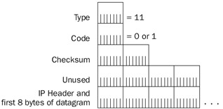
Figure 8-12: The structure of the ICMP Time Exceeded message.
The fields in the ICMP Time Exceeded message are defined as follows:
- TypeSet to 11.
- CodeSet to 0 or 1. Set to 0 by a router to indicate a TTL expiration (the ICMP Time Exceeded-TTL Exceeded in Transit message). Set to 1 by a destination host to indicate a reassembly expiration (the ICMP Time Exceeded-Fragment Reassembly Time Exceeded message).
- IP Header + First 8 Bytes Of Discarded DatagramTo identify the discarded IP datagram, the ICMP Time Exceeded message contains the IP header and the first 8 bytes of the IP payload.
Network Monitor Capture 08-05 (in the Captures folder on the companion CD-ROM) shows an ICMP Echo message from an Internet host sent to an Internet Web site with an insufficient TTL.
ICMP Parameter Problem
A router or a destination host sends an ICMP Parameter Problem message when anerror occurs in the processing of the IP header that causes the IP datagram to be discarded, and there are no other ICMP messages that can be used to indicate the error. ICMPParameter Problem messages can be sent because of errors in TCP/IP implementations causing incorrect formatting of IP header fields. Typically, ICMP Parameter Problem messages are sent because of incorrect arguments in IP option fields. Figure 8-13 shows the ICMP Parameter Problem message structure.
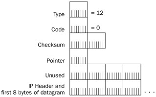
Figure 8-13: The structure of the ICMP Parameter Problem message.
The fields in the ICMP Parameter Problem message are defined as follows:
- TypeSet to 12.
- CodeSet to 0–2. See Table 8-5.
- PointerA 1-byte field set to the byte offset (starting at 0) in the encapsulated IP header where the error was detected for Parameter Problem messages with the Code field set to 0.
- IP Header + First 8 Bytes Of Discarded DatagramTo identify the discarded IP datagram, the ICMP Parameter Problem message contains the IP header and the first 8 bytes of the IP payload.
Table 8-5: ICMP Parameter Problem Code Values Code Value
Meaning
0
Pointer indicates error
1
Missing a required option
2
Bad length
Note ICMP Parameter Problem messages are never sent for IP datagrams with an invalid checksum. IP datagrams that fail the checksum are silently discarded.
ICMP Address Mask Request and Address Mask Reply
The ICMP Address Mask Request and Address Mask Reply messages were introduced in RFC 950 as a method for an IP node to discover its subnet mask. When subnetting, a class-based subnet mask based on the first three bits of the IP address can no longer be assumed. An IP node can send an ICMP Address Mask Request as directed traffic to a known router or as a broadcast using either the all-subnets-directed broadcast or the limited broadcast IP address. If an IP node does not know its IP address, it can send the ICMP Address Mask Request with a source IP address of 0.0.0.0. The subsequent ICMP Address Mask Reply must then be sent as a broadcast.
The ICMP Address Mask Reply is sent by a router and contains the 32-bit subnet mask for the network segment on which the Address Mask Request was received. If no Address Mask Reply is received, the IP node assumes a class-based subnet mask.
The ICMP Address Mask Request and Address Mask Reply messages have the structure shown in Figure 8-14.
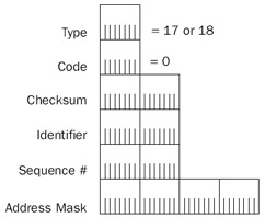
Figure 8-14: The structure of the ICMP Address Mask Request and Reply messages.
The fields in the ICMP Address Mask Request and Address Mask Reply messages are defined as follows:
- TypeSet to 17 for the Address Mask Request and 18 for the Address Mask Reply.
- CodeSet to 0.
- IdentifierOptionally used to match an Address Mask Reply with its original Address Mask Request.
- Sequence NumberAlso optionally used to match an Address Mask Reply with its original Address Mask Request.
- Address MaskThe 32-bit subnet mask corresponding to the IP host's network or subnet. The Address Mask field is set to 0.0.0.0 in the Address Mask Request and the 32-bit subnet mask of the network segment in the Address Mask Reply.
In TCP/IP for the Windows Server 2003 family, ICMP Address Mask Reply messagebehavior is controlled by the following registry setting:
EnableAddrMaskReply
Location: HKEY_LOCAL_MACHINESYSTEMCurrentControlSetServices
TcpipParameters
Data type: REG_DWORD
Valid range: 0-1
Default: 0
Present by default: No
EnableAddrMaskReply enables (when set to 1) and disables (when set to 0) the sending of an Address Mask Reply message after the receipt of an Address Mask Request message. By default, the sending of Address Mask Reply messages is disabled.
Ping Utility
The Ping command-line utility for the Windows Server 2003 family is the primary network tool for troubleshooting IP connectivity. The Ping utility tests reachability, name resolution, source routing, network latency, and other issues for both IP version 4 (IPv4) and IP version 6 (IPv6). For IPv4, Ping sends an ICMP Echo message to a specified destination and records the round-trip time, the number of bytes sent, and the corresponding Echo Reply's TTL. When Ping finishes sending ICMP Echo messages, it displays statistics on the average number of replies and round-trip time. For IPv6, Ping works the same way and performs the same functions only using Internet Control Message Protocol version 6 (ICMPv6) Echo Request messages.
When you ping a destination IPv4 address, the default behavior is to send four fragmentable, non-source-routed ICMP Echo messages with an Optional Data field of 32 bytes and wait four seconds for the corresponding ICMP Echo Reply. When you ping a name, normal name resolution mechanisms resolve the name to an IPv4 or IPv6 addressbefore the ICMP Echo or ICMPv6 Echo Request messages are sent. If TCP/IP for theWindows Server 2003 family is unable to resolve the name to an address, the Ping utility displays an error message. If a corresponding Echo Reply is not received within four seconds, Ping displays the error message "Request Timed Out."
In the ICMP header of Ping-generated ICMP Echo messages in the Windows Server 2003 family:
- The Identifier field is set to 768 (0x300).
- The Sequence Number field for the first Echo message is chosen as a multiple of 256 (0x100) and the Sequence Number for subsequent Echo messages is incremented by 256 (0x100).
- The Optional Data field is 32 bytes (by default), consisting of the string "abcdefghijklmnopqrstuvwabcdefghi."
Ping Options
Table 8-6 lists the use and default values of Ping utility options.
|
Option |
Use |
Default |
|---|---|---|
|
-t |
Sends Echo messages until interrupted. |
Not used |
|
-a |
Performs a Domain Name System (DNS) reverse query to resolve the DNS host name of the specified address. |
Not used |
|
-n count |
The number of Echo messages to send. |
4 |
|
-l size |
The size of the Optional Data field up to a maximum of 65,500. |
32 |
|
-f |
Sets the DF flag to 1. This switch is only valid for IPv4 traffic. |
Not used |
|
-i TTL |
Sets the value of the TTL field in the IPv4 header or the Hop Limit field in the IPv6 header. |
128 |
|
-v TOS |
Sets the value of the TOS field in the IPv4 header. The TOS value is in decimal notation. This switch is only valid for IPv4 traffic. |
0 |
|
-r count |
Sends the ICMP Echo messages using the IP Record Route option and sets the value of the number of slots. Count has a maximum value of 9. This switch is only valid for IPv4 traffic. |
Not used |
|
-s count |
Sends the ICMP Echo messages using the IP Internet Timestamp option and sets the value of the number of slots. Count has a maximum value of 4. In the Windows Server 2003 family, Ping uses the Internet Timestamp flag set to 1 (records both the IP addresses of each hop and the timestamp). This switch is only valid for IPv4 traffic. |
Not used |
|
-j host-list |
Sends the ICMP Echo messages using the Loose Source Route option and sets the next-hop addresses to the IP addresses in the host list. The host list is made up of IP addresses separated by spaces corresponding to the loose source route. There can be up to nine IP addresses in the host list. This switch is valid only for IPv4 traffic. |
Not used |
|
-k host-list |
Sends the ICMP Echo messages using the Strict Source Route option and sets the next-hop addresses to the IP addresses in the host list. The host list is made of IP addresses separated by spaces corresponding to the strict source route. There can be up to nine IP addresses in the host list. This switch is only valid for IPv4 traffic |
Not used |
|
-w timeout |
Waits the specified amount of time, in milliseconds, for the corresponding Echo Reply before displaying a Request Timed Out message. |
4000 |
|
-R |
Forces Ping to trace the round-trip path by sending the ICMPv6 Echo Request message to the destination and including an IPv6 Routing extension header with the next destination of the sending node. This switch is only valid for IPv6 traffic. |
Not used |
|
-S sourceaddr |
Forces Ping to use a specified source address. This switch is only valid for IPv6 traffic. |
Not used |
|
-4 |
Forces Ping to use an IPv4 address when the DNS name query for a host name returns both IPv4 and IPv6 addresses. |
Not used |
|
-6 |
Forces Ping to use an IPv6 address when the DNS name query for a host name returns both IPv4 and IPv6 addresses. |
Not used |
Network Monitor Example
The following Network Monitor trace (Capture 08-01 in the Captures folder on the companion CD-ROM) illustrates a summary of a typical use of the Ping utility to ping a destination IPv4 address. Four Echo messages are sent and four Echo Reply messages are received. The summarized frames have been indented for readability.
Frame Time Src MAC Addr Dst MAC Addr Protocol Description
1 0.271 0060083E4607 00502AB9A440 ICMP Echo, From
 157.59.11.19 To 157.59.08.01
2 0.271 00502AB9A440 0060083E4607 ICMP Echo Reply, To
 157.59.11.19 From 157.59.08.01
3 1.271 0060083E4607 00502AB9A440 ICMP Echo, From
 157.59.11.19 To 157.59.08.01
4 1.271 00502AB9A440 0060083E4607 ICMP Echo Reply, To
 157.59.11.19 From 157.59.08.01
5 2.273 0060083E4607 00502AB9A440 ICMP Echo, From
 157.59.11.19 To 157.59.08.01
6 2.273 00502AB9A440 0060083E4607 ICMP Echo Reply, To
 157.59.11.19 From 157.59.08.01
7 3.275 0060083E4607 00502AB9A440 ICMP Echo, From
 157.59.11.19 To 157.59.08.01
8 3.275 00502AB9A440 0060083E4607 ICMP Echo Reply, To
 157.59.11.19 From 157.59.08.01
Tracert Utility
The Tracert utility uses ICMP Echo or ICMPv6 Echo Request messages to determine the path—the series of routers—that unicast IPv4 and IPv6 traffic takes from a source host to a destination host. Tracert tests reachability, name resolution, network latency,routing loops, and other issues.
When you tracert a destination IP address, the default behavior is to trace the route and report the round-trip time, the near-side router IP address, and the DNS name corresponding to the near-side router IP address. When you tracert a name, normal name resolution techniques resolve the name to an IP address before the ICMP Echo messages are sent. If TCP/IP for the Windows Server 2003 family is unable to resolve the name to an IP address, the Tracert utility displays an error message.
Tracert for IPv4 destinations works in the following manner:
- An ICMP Echo message is sent to the destination with the TTL in the IP header set to 1. If the destination is on a directly attached network, the destinationresponds with a corresponding Echo Reply message and Tracert is done.
- If the destination is not in a directly attached network, the ICMP Echo message is forwarded to an IP router.
- The IP router determines that the IP datagram is transit traffic (not destined for the router) and decrements the TTL. Because the TTL is now 0, the IP router discards the IP datagram and sends back an ICMP Time Exceeded-TTL Exceeded in Transit message to the sending host with the source IP address set to the IP address of the interface on which the ICMP Echo message was received. The interface on which the ICMP Echo message was received is the near-side interface, the interface that is the smallest number of hops from the sending host.
- After receipt of the ICMP Time Exceeded-TTL Exceeded in Transit message, the Tracert utility records the round-trip time and the source IP address.
- Tracert sends two more ICMP Echo messages and records their round-trip time.
- An ICMP Echo message is sent to the destination with the IP header's TTL set to 2. The Echo is forwarded to a neighboring IP router.
- The neighboring IP router determines that the IP datagram is transit traffic, decrements the TTL to 1, and forwards it to the next hop or the final destination.
- If the destination is on a directly attached network, the destination responds with a corresponding Echo Reply and Tracert is done.
- If the destination is not on a directly attached network, the IP router determines that the IP datagram is transit traffic and decrements the TTL. Because the TTL is now 0, the IP router discards the IP datagram and sends back an ICMP Time Exceeded-TTL Exceeded in Transit message to the sending host with the sourceIP address set to the IP address of the interface on which the ICMP Echo was received. The interface on which the ICMP Echo was received is the near-side interface, the interface that is the smallest number of hops from the sending host.
- After receipt of the ICMP Time Exceeded-TTL Exceeded in Transit message, the Tracert utility records the round-trip time and the source IP address.
- Tracert sends two more ICMP Echo messages and records their round-trip time.
This process continues until the destination is reached and replies with ICMP Echo Reply messages.
The Tracert utility records the series of near-side router interfaces in the path from the sending host to a destination. By default, Tracert also performs a DNS reverse query on each near-side router interface and displays the host name corresponding to the IP address. You can prevent this behavior and speed up the completion of Tracert by using the -d option.
| Note |
If a router silently discards packets with an expired TTL, Tracert shows a series of * characters for that hop. If ICMP packet filtering is occurring on a near-side router interface, that router and all subsequent routers show the * character until 30 hops are attempted (the default). |
Network Monitor Example
The following frames from a Network Monitor trace (Capture 08-06 in the Captures folder on the companion CD-ROM) summarize a typical use of the Tracert utility to trace the route to a destination IP address. In this case, Tracert is used to trace the path across two routers, and the -d option is used to simplify the process and the display. The summarized frames have been indented for readability.
Frame Time Src MAC Addr Dst MAC Addr Protocol Description
1 1.241 0060083E4607 00502AB9A440 ICMP Echo, From
 157.59.11.19 To 157.59.224.33
2 1.241 00502AB9A440 0060083E4607 ICMP Time Exceeded
 while trying to deliver to
 157.59.224.33 See frame 1
3 1.242 0060083E4607 00502AB9A440 ICMP Echo, From
 157.59.11.19 To 157.59.224.33
4 1.242 00502AB9A440 0060083E4607 ICMP Time Exceeded
 while trying to deliver to
 157.59.224.33 See frame 3
5 1.260 0060083E4607 00502AB9A440 ICMP Echo, From
 157.59.11.19 To 157.59.224.33
6 1.260 00502AB9A440 0060083E4607 ICMP Time Exceeded
 while trying to deliver to
 157.59.224.33 See frame 5
7 2.263 0060083E4607 00502AB9A440 ICMP Echo, From
 157.59.11.19 To 157.59.224.33
8 2.263 00502AB9A440 0060083E4607 ICMP Time Exceeded
 while trying to deliver to
 157.59.224.33 See frame 7
9 2.264 0060083E4607 00502AB9A440 ICMP Echo, From
 157.59.11.19 To 157.59.224.33
10 2.265 00502AB9A440 0060083E4607 ICMP Time Exceeded
 while trying to deliver to
 157.59.224.33 See frame 9
11 2.265 0060083E4607 00502AB9A440 ICMP Echo, From
 157.59.11.19 To 157.59.224.33
12 2.266 00502AB9A440 0060083E4607 ICMP Time Exceeded
 while trying to deliver to
 157.59.224.33 See frame 11
13 3.264 0060083E4607 00502AB9A440 ICMP Echo, From
 157.59.11.19 To 157.59.224.33
14 3.265 00502AB9A440 0060083E4607 ICMP Echo Reply, To
 157.59.11.19 From 157.59.224.33
15 3.266 0060083E4607 00502AB9A440 ICMP Echo, From
 157.59.11.19 To 157.59.224.33
16 3.267 00502AB9A440 0060083E4607 ICMP Echo Reply, To
 157.59.11.19 From 157.59.224.33
17 3.268 0060083E4607 00502AB9A440 ICMP Echo, From
 157.59.11.19 To 157.59.224.33
18 3.268 00502AB9A440 0060083E4607 ICMP Echo Reply, To
 157.59.11.19 From 157.59.224.33
Frames 1 through 6 are the first hop. In Frames 1, 3, and 5, the IP header's TTL is set to 1. The local router decrements the TTL to 0 and sends back ICMP Time Exceeded-TTL Exceeded in Transit messages (Frames 2, 4, and 6).
Frames 7 through 12 are the second hop. In Frames 7, 9, and 11, the IP header's TTL is set to 2. The second router in the path decrements the TTL to 0 and sends back the ICMP Time Exceeded-TTL Exceeded in Transit messages (Frames 8, 10, and 12).
Frames 13 through 18 reach the destination. In Frames 13, 15, and 17, the IP header's TTL is set to 3, which is an adequate TTL to reach a destination two routers away. The destination sends back the appropriate Echo Reply messages (Frames 14, 16, and 18).
| Tip |
The round-trip times reflected in the Tracert display are not necessarily the same round-trip times for normal traffic. Most routers process ICMP errors and messages at a lower priority. Therefore, the round-trip times reflected in the Tracert display might be larger than the round-trip times for normal traffic. Additionally, it is possible for network conditions and the path to change during the route-tracing process, giving misleading results. |
Tracert Options
Table 8-7 lists the use and default values of Tracert utility options.
|
Option |
Use |
Default |
|---|---|---|
|
-d |
Instructs Tracert to not perform a DNS reverse query on every router IP address. If the host name of each router is unimportant, using the -d option speeds up the Tracert display of the path |
Performs DNS reverse queries on each router IP address |
|
-h max_hops |
Instructs Tracert to increment the TTL up to max_hops. |
30 |
|
-j host-list |
Sends the ICMP Echo messages using the loose source route specified in the host-list. The host list is up to nine IP addresses separated by spaces corresponding to the loose source route to the destination. This switch is valid only for IPv4 traffic. |
Not used |
|
-w timeout |
Waits the specified amount of time in milliseconds for the response before displaying a *. |
4000 |
|
-R |
Forces Tracert to trace the round-trip path by sending the ICMPv6 Echo Request message to the destination and including an IPv6 Routing extension header with the next destination of the sending node. This switch is valid only for IPv6 traffic. |
Not used |
|
-S sourceaddr |
Forces Tracert to use a specified source address. This switch is valid only for IPv6 traffic. |
Not used |
|
-4 |
Forces Tracert to use an IPv4 address when the DNS name query for a host name returns both IPv4 and IPv6 addresses. |
Not used |
|
-6 |
Forces Tracert to use an IPv6 address when the DNS name query for a host name returns both IPv4 and IPv6 addresses. |
Not used |
Pathping Utility
The Pathping command-line utility for the Windows Server 2003 family is used to test router and link latency and packet losses for both IPv4 and IPv6. For IPv4, Pathping works by sending successive ICMP Echo messages to each point in the path and recording the following: the average round-trip time, the packet loss when sending ICMP Echo messages to each router, and the packet loss when sending ICMP Echo messages across the links between each router.
The following is an example of the display of the Pathping utility:
C:>pathping 10.10.2.99
Tracing route to 10.10.2.99 over a maximum of 30 hops
 0 10.0.1.100
 1 10.0.1.1
 2 192.168.1.2
 3 172.16.1.2
 4 10.10.2.99
Computing statistics for 100 seconds...
 Source to Here This Node/Link
Hop RTT Lost/Sent = Pct Lost/Sent = Pct Address
 0 10.0.1.100
 0/ 100 = 0% |
 1 0ms 0/ 100 = 0% 0/ 100 = 0% 10.0.1.1
 0/ 100 = 0% |
 2 0ms 0/ 100 = 0% 0/ 100 = 0% 192.168.1.2
 0/ 100 = 0% |
 3 0ms 0/ 100 = 0% 0/ 100 = 0% 172.16.1.2
 0/ 100 = 0% |
 4 1ms 0/ 100 = 0% 0/ 100 = 0% 10.10.2.99
Trace complete.
In this example, Pathping is sending ICMP Echo messages from a sending host (10.0.1.100) to a destination host (10.10.2.99) across three routers (10.0.1.1, 192.168.1.2, and 172.16.1.2). Pathping first resolves the path using the same method as Tracert. Next, Pathping sends ICMP Echo messages to each near-side router interface and to the destination (in the path order), and repeats this process 99 times. In this example, the Tracert utility sends an ICMP Echo message to 10.0.1.1, then to 192.168.1.2, then to 172.16.1.2, then to the destination, 10.10.2.99. This process is repeated 99 times so that 100 ICMP Echo messages are sent to each near-side router interface in the path and the destination. From the responses (and lack of responses), Pathping accumulates statistics for the following:
- Packet losses for packets sent on the link between the source host (10.0.1.100) and the first router (10.0.1.1)
- Packet losses and average round-trip times for packets sent to the first router in the path (with the near-side interface of 10.0.1.1)
- Packet losses for packets sent on the link between the first router (10.0.1.1) and the second router in the path (with the near-side interface of 192.168.1.2)
- Packet losses and average round-trip times for packets sent to the second router in the path (192.168.1.2)
- Packet losses for packets sent on the link between the second router (192.168.1.2) and the third router in the path (with the near-side interface of 172.16.1.2)
- Packet losses and average round-trip times for packets sent to the third router in the path (172.16.1.2)
- Packet losses for packets sent on the link between the third router (172.16.1.2) and the destination (10.10.2.99)
- Packet losses and average round-trip times for packets sent to the destination (10.10.2.99)
The Source To Here column displays the average round-trip time and packet loss for packets destined to a specific IP address. These packets must be processed as the destination and an ICMP Echo Reply message must be constructed and sent. The This Node/Link column displays the packet loss for packets that are either traveling across a link (as indicated by | in the Address column), across a router (as indicated by an intermediate router IP address in the Address column), or to the destination (as indicated by the destination IP address in the Address column). Packets sent across a router are typically forwarded using an optimized forwarding process that is much faster than responding as the destination of an ICMP Echo Reply message.
Network Monitor Capture 08-07 (in the Captures folder on the companion CD-ROM) contains the traffic of the Pathping utility for this example.
Pathping Options
Table 8-8 lists the use and default values of Pathping utility options.
|
Option |
Use |
Default |
|---|---|---|
|
-n |
Instructs Pathping to not perform a DNS reverse query on every router IP address. If the host name of each router is unimportant, the -n option accelerates the Pathping display of the path. |
Performs DNS reverse queries on each router IP address |
|
-h max_hops |
Instructs Pathping to increment the TTL up to max_hops. |
30 |
|
-g host-list |
Sends the ICMP Echo messages using the loose source route specified in the host-list. The host list is up to nine IP addresses separated by spaces corresponding to the loose source route to the destination. |
Not used |
|
-p period |
Waits the specified amount of time in milliseconds between successive Echo messages. |
250 |
|
-q num_queries |
Sends the num_queries number of queries for each hop. |
100 |
|
-w timeout |
Waits the specified amount of time in milliseconds for the response. |
3000 |
|
-4 |
Forces Pathping to use an IPv4 address when the DNS name query for a host name returns both IPv4 and IPv6 addresses. |
Not used |
|
-6 |
Forces Pathping to use an IPv6 address when the DNS name query for a host name returns both IPv4 and IPv6 addresses. |
Not used |
Summary
ICMP is a set of messages that provides services that are not part of IP. ICMP includes the following services: diagnostic (Echo and Echo Reply messages), delivery error reporting (Destination Unreachable, Time Exceeded, Source Quench, and Redirect messages), router discovery (Router Advertisement and Router Solicitation messages), IP header problems (Parameter Problem message), and address mask discovery (Address Mask Request and Address Mask Reply messages). The ICMP Destination Unreachable-Fragmentation Needed And DF Set message is used for PTMU Discovery. The Ping, Tracert, and Pathping utilities provided with the Windows Server 2003 family use ICMP messages toprovide diagnostic functionality.
Part I - The Network Interface Layer
- Local Area Network (LAN) Technologies
- Wide Area Network (WAN) Technologies
- Address Resolution Protocol (ARP)
- Point-to-Point Protocol (PPP)
Part II - Internet Layer Protocols
- Internet Protocol (IP) Basics
- Internet Protocol (IP) Addressing
- Internet Protocol (IP) Routing
- Internet Control Message Protocol (ICMP)
- Internet Group Management Protocol (IGMP)
- Internet Protocol Version 6 (IPv6)
Part III - Transport Layer Protocols
- User Datagram Protocol
- Transmission Control Protocol (TCP) Basics
- Transmission Control Protocol (TCP) Connections
- Transmission Control Protocol (TCP) Data Flow
- Transmission Control Protocol (TCP) Retransmission and Time-Out
Part IV - Application Layer Protocols and Services
- Dynamic Host Configuration Protocol (DHCP) Server Service
- Domain Name System (DNS)
- Windows Internet Name Service (WINS)
- File and Printer Sharing
- RADIUS and Internet Authentication Service
- Internet Information Services (IIS) and the Internet Protocols
- Internet Protocol Security (IPSec)
- Virtual Private Networks (VPNs)
EAN: N/A
Pages: 216
