Virtual Private Networks (VPNs)
Overview
Computer networks have become a central part of the corporate infrastructure in organizations of all sizes. A challenge that continues to face organizations is how to connect remote sites and remote users in the most reliable, flexible, and cost-effective manner. A similar issue confronts individual corporate remote users who need to access their e-mail and internal servers while away from the office.
Traditionally, remote sites were connected to a central corporate hub by the use of leased lines, frame relay, or Asynchronous Transfer Mode (ATM) networks. Remote users were served by dial-in networking facilities, often using inbound free phone numbers. These approaches tend to be expensive and inflexible, however. The basic unit costs of leased lines and inbound free phone facilities continue to decline in real terms, but the bandwidth required and the overall costs to the organization rise. In addition, the infrastructure becomes harder to manage. These approaches can also lead to pressure on flexibility. The lead time required for a leased line can be substantial, depending on the source and destination, and often a minimum-length contract is required. Organizations today need greater flexibility.
A virtual private network (VPN) enables you to create a secure private network utilizing some other public network such as the Internet, which might be less secure. The data is kept private as it is traveling across the VPN by means of encapsulation, authentication, and encryption.
VPN technology provides a secure, scalable, cost-effective solution to the connectivity issue. It allows an organization to connect remote sites to a central site securely over the Internet and enables remote users to connect securely to the corporate network using local Internet service providers (ISPs). In these VPN usage scenarios, a physical connection is made using an ISP. The VPN connection appears to remote access users as though they are on a private network. The VPN connection appears as a private link to the routers of the remote site.
The subject of VPNs is extensive enough to warrant a complete book of its own, and therefore is not covered comprehensively in this book. For our purposes, this chapter gives an overview of VPNs and focuses on the two VPN protocols that the Microsoft Windows Server 2003 family implements: Point-to-Point Tunneling Protocol (PPTP) and Layer 2 Tunneling Protocol with Internet Protocol Security (L2TP/IPSec). These two VPN protocols leverage the Point-to-Point Protocol (PPP) for authentication, compression, initial data encapsulation, and, for PPTP, data encryption.
Overview of VPNs
As Figure 23-1 illustrates, a VPN connection links either a single computer or a network to another network across an intermediate network, typically the Internet.
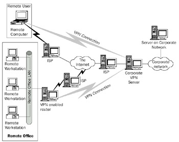
Figure 23-1: Virtual private networking.
When connecting a remote user using a VPN connection, the remote user first establishes a normal dial-up connection to a local ISP. Users with broadband Internet access or those who are connecting to a VPN server on an organization's network use their local network connection. After this connection is established, the remote user can establish a VPN connection between the remote computer and the organization's VPN server.
Connecting a remote network to the corporate network using a VPN connection is a similar process. In this scenario, the remote office's VPN-enabled router initiates the VPN connection on behalf of clients on the local area network (LAN). The type of connection between the remote router and the ISP is not important, as long as it can carry IP traffic.
VPN Clients and Servers
The computer initiating the VPN connection is referred to as the VPN client. The computer responding to the initiation of the VPN connection is referred to as the VPN server. In the remote access scenario, the remote computer is the VPN client that makes aremote access connection to the VPN server. This remote computer therefore has two active connections established (one to the ISP, the other for the VPN). In the remote office scenario, the remote office's router is the VPN client, which makes a router-to-router (also known as site-to-site) VPN connection to the VPN server. In both scenarios, the VPN server is a server in the organization that acts as the end point for the VPN connection.
Therefore, the following two types of VPN connections can be constructed:
- The remote access VPN connectionA remote access user connects to an organization's intranet.
- The router-to-router VPN connectionA router connects a remote network to an organization's intranet.
VPN Protocols
Connections between a VPN client and a VPN server are implemented through the use of one of two VPN protocols: PPTP or L2TP/IPSec. PPTP is a Layer 2 protocol thatencapsulates IP datagrams in PPP frames, which are in turn encapsulated in IP datagrams for transmission over an IP internetwork. PPTP is an older VPN protocol that Microsoft helped develop. L2TP, on the other hand, is a newer Layer 2 protocol based on both Cisco's Layer 2 Forwarding (L2F) protocol and PPTP, which encapsulates IP datagrams in PPP frames to be sent over IP, X.25, frame relay, or ATM.
From an end user point of view, these protocols are functionally equivalent. The key technical differences between PPTP and L2TP are as follows:
- PPTP requires that the transit network be IP-based. L2TP requires only that the transit network provide packet-level connectivity. L2TP can be used over IP (using UDP) or directly over frame relay, X.25, or ATM. PPTP can traverse these networks also, but additional protocol overhead is required because it must work within IP.
- PPTP can support only a single tunnel between the VPN client and VPN server. L2TP allows for the use of multiple tunnels between end points. With L2TP, you can create different tunnels for different qualities of service or for different security requirements.
- L2TP provides header compression. When header compression is enabled, L2TP operates with 4 bytes of overhead, as compared to 6 bytes for PPTP.
Historically, the preferred VPN protocol is PPTP, due to its early inclusion withWindows NT 4.0 and its support in all recent versions of Windows, including Windows Server 2003. However, L2TP/IPSec should become the predominant VPN protocol in the future due to the availability of Microsoft L2TP/IPSec VPN Client—a free download that enables computers running Windows 98, Windows Millennium Edition (Windows Me), and Windows NT Workstation 4.0 to make L2TP/IPSec connections—and the new IPSec Network Address Translator Traversal (NAT-T) support, which allows IPSec negotiations and Encapsulating Security Payload (ESP)–protected traffic to traverse a NAT.
Another method of creating VPN connections is to use IPSec tunnel mode. However, IPSec tunnel mode is not used for remote access connections because there is no standard mechanism for user-level authentication and IP address assignment. IPSec tunnel mode can be used for router-to-router VPN connections. However, an IPSec tunnel is not recognized as a routing interface by the Routing and Remote Access service. In contrast, PPTP and L2TP/IPSec demand-dial interfaces are recognized as a routing interface, by the Routing and Remote Access service. Routes can be assigned to use a PPTP or L2TP/IPSec interface, and routing protocols such as Routing Information Protocol (RIP) and Open Shortest Path First (OSPF) can operate over them. It is possible to create IPSec packet filters that emulate routes, but this is more difficult to configure and route changes must be done manually. Therefore, IPSec tunnel mode for router-to-router VPN connections is only recommended when connecting to a third-party router or security gateway that does not support PPTP or L2TP/IPSec.
Tunneling
Both L2TP and PPTP implement VPNs by means of tunneling, the encapsulation of an IP datagram within another datagram. As Figure 23-2 illustrates, the VPN client encapsulates the original IP datagram sent between two end systems, and sends it to the VPN server, where the datagram is unwrapped and forwarded on the local network.
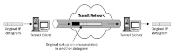
Figure 23-2: Tunneling in VPNs.
As Figure 23-2 illustrates, an IP datagram to be sent between the VPN client and a VPN server is encapsulated inside a new IP datagram. This datagram is then sent from the VPN client to the VPN server. The new IP datagram has a header that provides the information necessary to enable the packet to be forwarded properly across the transit network.
At the VPN server, the datagram is unwrapped and the original IP datagram can then be forwarded from the VPN server. After the original datagram is unwrapped, the VPN server acts as a router and makes a forwarding decision on the original packet based on the configuration of the VPN server and the entries in the VPN server's routing table.
The VPN tunneling is achieved through the use of a Network Driver Interface Specification (NDIS) driver that becomes an IP client. This is illustrated in Figure 23-3, which shows the architecture of a VPN connection in the remote access scenario.
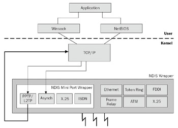
Figure 23-3: Tunneling architecture.
An application on the remote computer uses either NetBIOS or Windows Sockets to send a datagram to a remote computer. The payload is sent to the TCP/IP component in the Windows Server 2003 family, which creates an IP datagram. At this stage in the process, the source and destination IP addresses are set as if the two systems were communicating directly.
After the IP datagram has been constructed, it is sent to the NDIS miniport for the VPN protocol in use. The miniport driver then encapsulates the original IP datagram with the header for the VPN and sends it back to the TCP/IP driver. The TCP/IP driver then constructs a new IP datagram, which, for PPTP, is sent to the appropriate NDIS driver for the transit network. For L2TP, the packet is intercepted by the IPSec components, which protect the L2TP message with IPSec ESP. For more information about ESP protection, see Chapter 22, "Internet Protocol Security (IPSec)."
VPNs and PPP
Both PPTP and L2TP/IPSec leverage PPP for most of the underlying mechanisms, such as authentication and compression. For PPTP, PPP encryption is also leveraged (for L2TP/IPSec, IPSec provides encryption). In effect, the VPN connection is a PPP connection between the VPN client and VPN server. This allows the original IP datagram to be transmitted inside a PPP frame, which is then encapsulated in an outer IP datagram fortransmission across the transit network.
PPTP connections must use Microsoft Challenge Handshake Authentication Protocol (MS-CHAP), MS-CHAP version 2, Extensible Authentication Protocol-Transport Level Security (EAP-TLS) for authentication in order for the PPTP data to be encrypted with Microsoft Point-to-Point Encryption (MPPE). L2TP/IPSec connections can use any type of PPP authentication, but MS-CHAP v2 or EAP-TLS is recommended.
For more information about PPP encapsulation, establishing PPP connections, or PPP authentication protocols, see Chapter 4, "Point-to-Point Protocol (PPP)."
VPN Address Assignment
When the VPN connection has been established, the VPN client appears to be a part of a central network and requires an IP address based on the central network. This means the VPN client typically has two IP addresses: one for the transit network (such as the Internet or local network) and one for the VPN connection.
The Windows Server 2003 Routing and Remote Access service allows the IP addresses to be provided by the user (as part of the configuration of the VPN connection) or to be assigned dynamically as part of setting up the VPN connection. Dynamically assigned addresses can be based on either a static pool of addresses or obtained by the Routing and Remote Access server from a Dynamic Host Configuration Protocol (DHCP) server.
VPN Data Compression
The VPN protocols support a PPP-based compression scheme. For Windows Server 2003, both PPTP and L2TP/IPSec use Microsoft Point-to-Point Compression (MPPC), which is defined in RFC 2118. For Windows Server 2003 VPN clients, the use of MPPC is controlled by settings in the properties of the VPN connection in Network Connections.
| More Info |
MPPC is defined in RFC 2118, which can be found in the Rfc folder on the companion CD-ROM. |
MPPC can reduce the total amount of data being transferred across the transit network by as much as 50 to 60 percent for text data, although for binary data, the compression might only amount to 2 to 3 percent or less. As with all data compression schemes, the percentage by which the original data can be compressed varies with the nature of the data.
VPN Data Encryption
For the data to be transferred securely across an insecure transit network, data encryption is required. PPTP supports the use of MPPE. MPPE is based on the RSA/RC4 encryption algorithm and uses 40-, 56-, or 128-bit encryption keys derived from the authentication process. MPPE relies on the initial key generated during user authentication and typically changes it with each packet.
L2TP/IPSec uses Data Encryption Standard (DES) with a 56-bit key or Triple-DES encryption with three 56-bit keys to protect the data stream from the client to the VPN server. IPSec negotiates a common encryption key during the establishment of the main mode security association (SA), and also refreshes it periodically. For more information about IPSec SAs, see Chapter 22.
PPTP
PPTP is a VPN protocol implemented at Layer 2 in the Open Systems Interconnection (OSI) model. PPTP encapsulates VPN data inside PPP frames, which are then further encapsulated in IP datagrams for transmission over a transit IP internetwork such as the Internet.
| More Info |
PPTP is documented in RFC 2637, which can be found in the Rfc folder on the companion CD-ROM. |
Creation and maintenance of a PPTP tunnel is carried out using a TCP connection. The VPN client uses a dynamically allocated TCP port, and the PPTP server listens on TCP port 1723. Subsequent data is encapsulated using a modified Generic Routing Encapsulation (GRE) header.
PPTP Data Encapsulation
As noted earlier, PPTP encapsulates the original IP datagram when it is transmitted between the PPTP client and PPTP server. Figure 23-4 shows the structure of a PPTP packet.
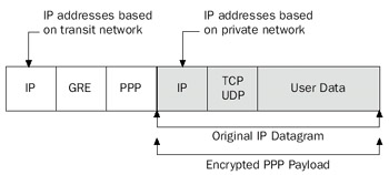
Figure 23-4: PPTP packet structure.
In Figure 23-4, the original datagram is first formatted as a PPP frame. Using PPP, this part of the datagram can be compressed using MPPC and encrypted using MPPE. The PPP frame is then encapsulated with a GRE header, which then becomes the payload of an IP packet sent between the PPTP client and server. The source and destination IPaddresses of this packet correspond to the IP addresses of the PPTP client and PPTP server. On the wire, this datagram will be further encapsulated in a Data Link Layer frame, with the appropriate header and trailer.
The GRE header used to encapsulate the PPP frame is modified for PPTP from its original definition in RFCs 1701 and 1702. The PPTP GRE header includes an Acknowledgment flag and a 32-bit Acknowledgment field, which is used to detect dropped PPTP packets. The PPTP GRE header also replaces the 32-bit Key field with a 16-bit Payload Length field and a 16-bit Call ID field. The Call ID field is used to indicate the PPTP tunnel through which the encapsulated data is traveling. GRE is a client protocol of IP using IP protocol 47.
Network Monitor Capture 23-01 (in the Captures folder on the companion CD-ROM) provides an example of PPTP encapsulation for an unencrypted ICMP Echo and Echo Reply message.
PPTP Control Connection
The PPTP control connection is a TCP connection between the VPN client and the VPN server that is used for PPTP tunnel management. There are PPTP processes for the following:
- PPTP control connection creation
- PPTP control connection maintenance
- PPTP control connection termination
PPTP control connections are managed by exchanging a series of PPTP messages. Each PPTP message is the payload of a TCP segment and has a different packet structure. For the details of the packet structure of PPTP control messages, see RFC 2637.
PPTP Control Connection Creation
The creation of a PPTP control connection between a Windows Server 2003 PPTP client and a Windows Server 2003 PPTP server consists of the following exchange of messages:
- A TCP connection is established from a dynamically allocated port used by the PPTP client to TCP port 1723 on the PPTP server.
- The PPTP client sends a PPTP Start-Control-Connection-Request message to establish a PPTP control connection.
- The PPTP server responds with a PPTP Start-Control-Connection-Reply message.
- The PPTP client sends a PPTP Outgoing-Call-Request message and selects a Call ID to identify the PPTP tunnel for data sent from the PPTP client to the PPTP server.
- The PPTP server responds with a PPTP Outgoing-Call-Reply message and selects its own Call ID to identify the PPTP tunnel for data sent from the PPTP server to the PPTP client.
- The PPTP client sends a PPTP Set-Link-Info message to indicate PPP-negotiated options.
After the PPTP control connection is established, the separate Call IDs selected by the PPTP client and PPTP server are used in the GRE header for sent data to identify the PPTP tunnel.
Network Monitor Capture 23-02 (in the Captures folder on the companion CD-ROM) provides an example of the creation of a PPTP control connection and the subsequent PPP negotiation (unencrypted).
PPTP Control Connection Maintenance
PPTP control connections are maintained by the exchange of PPTP Echo-Request and PPTP Echo-Reply messages. Either the PPTP client or the PPTP server can send the initial PPTP Echo-Request message.
Network Monitor Capture 23-03 (in the Captures folder on the companion CD-ROM) provides an example of PPTP control connection maintenance.
PPTP Control Connection Termination
The termination of a PPTP control connection between a Windows Server 2003 PPTP client and a Windows Server 2003 PPTP server consists of the following exchange of messages:
- The Link Control Protocol (LCP) connection between the PPTP client and PPTP server is terminated.
- The PPTP server sends a PPTP Clear-Call-Request message indicating that the PPTP control connection is to be terminated.
- The PPTP client responds with a PPTP Call-Disconnected-Notify message.
- The PPTP server sends a PPTP Stop-Control-Connection-Request message to terminate the PPTP control connection.
- The PPTP client responds with a PPTP Stop-Control-Connection-Reply message.
- The TCP connection is terminated in the normal way.
This example assumes that the PPTP client terminated the connection.
Network Monitor Capture 23-04 (in the Captures folder on the companion CD-ROM) provides an example of a PPTP control connection termination.
L2TP IPSec
L2TP operates, as its name suggests, at Layer 2 in the International Organization for Stand-ardization (ISO) model, and is a network protocol that creates a tunnel between an L2TP client and an L2TP server, and then encapsulates PPP frames to be sent over the tunnel. When using IP as the transport protocol, L2TP can be used as a VPN protocol over the Internet. L2TP was designed so that it can be used directly over various WAN media such as frame relay or X.25 without an IP transport layer. This can extend its usefulness in setting up corporate networks.
| More Info |
L2TP is documented in RFC 2661, which can be found in the Rfc folder on the companion CD-ROM. |
When L2TP is used over IP internetworks, it uses UDP for tunnel creation and maintenance, as well as for data transmission. With L2TP, both the tunneled data and the control messages share a single UDP stream, which can simplify the passing of VPN data through corporate firewalls. L2TP traffic sent by the Windows Server 2003 VPN client and server use UDP port 1701 for both the source and destination UDP ports.
L2TP in Windows Server 2003 and Windows XP relies on IPSec for encryption, and the combination of L2TP and IPSec is known as L2TP/IPSec. Both the VPN client and the VPN server must support both L2TP and IPSec. Before the first L2TP message is sent, a set of IPSec SAs is negotiated between the L2TP client and L2TP server to protect IPSec negotiation and L2TP traffic. By default, L2TP in Windows Server 2003 and Windows XP uses certificates for IPSec peer authentication. However, both Windows Server 2003 and Windows XP can be configured manually to use preshared keys for IPSec peer authentication.
For more information about IPSec, see Chapter 22.
L2TP IPSec Data Encapsulation
As with PPTP, L2TP encapsulates a PPP frame containing an IP datagram when transferred across the transit network. Because IPSec provides the encryption facilities, L2TP/IPSec encapsulation takes place in two phases. Figure 23-5 illustrates the initial L2TP encapsulation and the IPSec encapsulation.
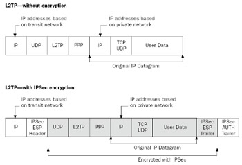
Figure 23-5: Two phases of encapsulation over L2TP.
As Figure 23-5 illustrates, the L2TP encapsulation involves the original datagram first being wrapped in a PPP frame, as with PPTP. The PPP frame is then inserted into a new IP datagram with a UDP header and an L2TP header. The L2TP client and the L2TP server for Windows Server 2003 and Windows XP both use UDP port 1701. However, the Windows Server 2003 L2TP server supports third-party L2TP clients that use a UDP port other than 1701.
The resulting IP datagram is then passed to the IPSec components, which add an IPSec ESP header and trailer. ESP protection provides data integrity, data origin authentication, data confidentiality (encryption), and replay protection. The outer IP header contains the source and destination IP addresses that correspond to the VPN client and server. Unlike normal IPSec policy, IPSec protection for L2TP traffic is provided by a rule that is automatically created by the remote access client and the Routing and Remote Access service.
Network Monitor Capture 23-05 (in the Captures folder on the companion CD-ROM) provides an example of L2TP encapsulation for an ICMP Echo and Echo Reply message (without IPSec protection).
L2TP Control Connection
The L2TP control connection is a logical connection between the VPN client and the VPN server that is used to send UDP-encapsulated L2TP messages for L2TP tunnel management. There are L2TP processes for the following:
- L2TP control connection creation
- L2TP control connection maintenance
- L2TP control connection termination
L2TP control connections are managed by exchanging a series of L2TP messages, each of which is the payload of a UDP message. For the details of the packet structure of the L2TP header and L2TP control messages, see RFC 2661.
Because the L2TP messages are sent over UDP, an unreliable protocol, L2TP provides its own sequencing through the use of a Next-Received (Nr) field, which indicates the next message number the sender is expecting to receive, and a Next-Sent (Ns) field, which indicates the message number of the sent message. Because L2TP supports multiple calls, or sessions, per tunnel, the L2TP header uses a Tunnel ID field that indicates the tunnel and a Session ID that indicates the session within the tunnel.
Because both L2TP-encapsulated data and L2TP control messages use an L2TP header, all L2TP control messages are encrypted with IPSec ESP for L2TP/IPSec.
L2TP Connection Creation
The creation of an L2TP control connection between a Windows Server 2003 L2TP client and a Windows Server 2003 L2TP server consists of the following exchange of messages:
- The L2TP client sends an L2TP Start-Control-Connection-Request message to establish an L2TP control connection.
- The L2TP server responds with an L2TP Start-Control-Connection-Reply message.
- The L2TP client sends an L2TP Start-Control-Connection-Connected message.
- The L2TP server responds with an L2TP Incoming-Call-Request message.
- The L2TP client sends an L2TP Incoming-Call-Connected message to indicate PPP-negotiated options.
After the L2TP control connection is established, the Tunnel ID and Session ID selected by the L2TP server in the L2TP Start-Control-Connection-Reply message is used in the L2TP header for encapsulated data to identify the L2TP session and tunnel. Network Monitor Capture 23-06 (in the Captures folder on the companion CD-ROM) provides an example of an L2TP connection creation (without IPSec protection).
L2TP Connection Maintenance
L2TP control connections are maintained by the sending of an L2TP Hello message by either the L2TP client or the L2TP server. The recipient of the L2TP Hello message sends an L2TP acknowledgment with an incremented Nr field.
Network Monitor Capture 23-07 (in the Captures folder on the companion CD-ROM) provides an example of L2TP connection maintenance (without IPSec protection).
L2TP Connection Termination
The termination of an L2TP control connection between a Windows Server 2003 L2TP client and a Windows Server 2003 L2TP server consists of the following exchange of messages:
- The LCP connection between the L2TP client and L2TP server is terminated.
- The L2TP client responds with an L2TP Call-Disconnected-Notify message, which contains the Tunnel ID, which identifies the L2TP tunnel, and theSession ID, which identifies the session within the L2TP tunnel.
- The L2TP server acknowledges the receipt of the L2TP Call-Disconnected-Notify message, which includes an incremented Nr field.
- The L2TP client sends a PPTP Stop-Control-Connection-Notification message to terminate the L2TP control connection.
- The L2TP server acknowledges the receipt of the L2TP Stop-Control-Connection-Notification message, which includes an incremented Nr field.
This example assumes that the VPN client terminated the L2TP connection.
Network Monitor Capture 23-08 (in the Captures folder on the companion CD-ROM) provides an example of an L2TP connection termination (without IPSec protection).
Part I - The Network Interface Layer
- Local Area Network (LAN) Technologies
- Wide Area Network (WAN) Technologies
- Address Resolution Protocol (ARP)
- Point-to-Point Protocol (PPP)
Part II - Internet Layer Protocols
- Internet Protocol (IP) Basics
- Internet Protocol (IP) Addressing
- Internet Protocol (IP) Routing
- Internet Control Message Protocol (ICMP)
- Internet Group Management Protocol (IGMP)
- Internet Protocol Version 6 (IPv6)
Part III - Transport Layer Protocols
- User Datagram Protocol
- Transmission Control Protocol (TCP) Basics
- Transmission Control Protocol (TCP) Connections
- Transmission Control Protocol (TCP) Data Flow
- Transmission Control Protocol (TCP) Retransmission and Time-Out
Part IV - Application Layer Protocols and Services
- Dynamic Host Configuration Protocol (DHCP) Server Service
- Domain Name System (DNS)
- Windows Internet Name Service (WINS)
- File and Printer Sharing
- RADIUS and Internet Authentication Service
- Internet Information Services (IIS) and the Internet Protocols
- Internet Protocol Security (IPSec)
- Virtual Private Networks (VPNs)
EAN: N/A
Pages: 216
