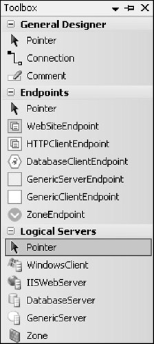
Logical Datacenter Designer Toolbox and Prototypes
As with Application Designer, initially the Logical Datacenter Designer toolbox will provide a set of preconfigured prototypes to which you can add your own. In this case, the prototypes are for servers, zones, and endpoints, as shown in Figure 3-1.

Figure 3-1
The following sections describe each prototype shown in Figure 3-1 in turn, though the set of prototypes available to you might be slightly different from those shown.
General
The first item you'll see in the General Designer section of the toolbox, and in the other sections for that matter, is Pointer. This is not an item to place on a diagram, but a mechanism for reverting the mouse cursor to a general selection pointer, thereby deselecting the prototype to which the mouse cursor is currently set:
-
Connection: Just as with the same-named item in the Application Designer toolbox, the Connection item enables you to connect endpoints together. However, the endpoints that you connect on Logical Datacenter Designer belong to servers and zones, rather than applications.
-
Comment: Once again, a Comment is just a free text note that adds clarity to your diagrams.
Endpoints
As will become clear later, communication pathways between servers are defined through the endpoints on those servers or through the zone endpoints that act as proxies to the server endpoints. Endpoints are typically "server" endpoints (for incoming communication) or client "endpoints" (for outgoing communication with those servers), but it is possible to alter the properties of an endpoint to make it bi-directional.
The endpoint prototypes provided by the toolbox shown in Figure 3-1 are as follows:
-
WebSiteEndpoint: This is a strongly typed endpoint through which a client may communicate with an IIS Web Server using the HTTP protocol. Our StockBroker example presented later includes two such endpoints.
-
HTTPClientEndpoint: This is the client-side counterpart of the server-side WebSiteEndpoint. Every connection to a WebSiteEndpoint will have a HTTPClientEndpoint, as you will see in our StockBroker example.
-
DatabaseClientEndpoint: This client endpoint represents the client side of a connection to a database server, such as SQL Server. Our StockBroker example will incorporate such a connection.
-
GenericServerEndpoint: The GenericServerEndpoint is a generalized endpoint for those situations in which a generic server accepts incoming communications via an unspecified protocol.
-
GenericClientEndpoint: This is the client-side counterpart of the GenericServerEndpoint.
-
ZoneEndpoint: This prototype represents an endpoint that constrains the type of communication that can travel into or out of a zone. In our StockBroker example, client and server endpoints will typically be coupled using zone endpoints as proxies, rather than being connected directly together.
Logical servers
Each of the logical server prototypes provided by the toolbox (refer to Figure 3-1) has specific settings and constraints appropriate to that server type. As you place logical servers onto a diagram, each will have, by default, zero, one, or more of the aforementioned endpoints. The prototypes are as follows:
-
WindowsClient: The WindowsClient prototype represents a machine running a Windows operating system, to which a Windows application may be deployed. You'll encounter one of these in our StockBroker example.
-
IISWebServer: This prototype represents an IIS Web Server instance capable of hosting ASP .NET web applications and Web services. We'll use this prototype twice in our StockBroker example.
-
DatabaseServer: This represents a database server such as Microsoft SQL Server.
-
GenericServer: The GenericServer represents a server in the broadest sense and is useful when you need to show a host to which a non-Microsoft-technologies application will be deployed.
-
Zone: A Zone represents a network region for which communication to and from the servers in that region is restricted to a specific set of protocols—by a firewall, a physical boundary, or both. There may in reality be no actual restriction mechanism; the zone describes a configuration constraint that, in effect, defines policy about connections that are permitted. This might be realized by a firewall or physical boundaries but may only exist logically as a means to constrain deployments. In our StockBroker example, we will place servers within zones.
EAN: 2147483647
Pages: 220