Exploring Network Address Translation
| NAT involves rewriting IP addresses in the IP packet header to a different IP address before routing the packet to its final destination. You can use the following two forms of NAT in your network to translate IP addresses:
Source Network Address TranslationIn order to protect internal resources in your network, you should assign private addresses to corporate computers that do not serve content to Internet clients. By privately addressing these computers, you hide them from the view of the public Internet. In contrast, you should assign publicly available server registered addresses and locate them on a secure segment of the network. By assigning your private corporate servers with private addresses, you conserve registered IP addresses for use on the publicly available servers. Note Network security and firewalls are discussed in Chapter 4, "Exploring Security Technologies and Network Infrastructure Design." To achieve registered address conservation and computer hiding, first assign private addresses to corporate computers within your corporate network, such as workstations or internal servers. Then apply one or more of the following policies on a NAT-capable device, such as a router or firewall:
Note The following ranges are designated as private IP addresses for their respective classes:
Static Network Address TranslationWith static NAT, publicly registered IP addresses are mapped one-to-one to privately addressed workstations and servers located on the inside of the firewall. When a privately addressed computer attempts to access an IP address on the Internet, the NAT device first rewrites the source IP of the packet before routing the packet to the outside network. Return packets are subsequently rewritten with the private IP address and the packets are routed to the appropriate internal computer. In Figure 3-13, the following static NAT entries are configured on the NAT device in order for the three inside clients to access outside services:
Figure 3-13. A Static NAT Example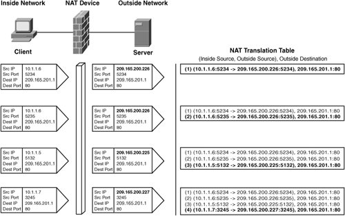 In Figure 3-13, a group of three users access an HTTP server with IP address 209.165.200.1. The NAT translation table on the right shows the NAT entries accumulating as the connections are translated on the NAT device. In the first two entries, the user with IP address 10.1.1.6 connects to the HTTP server twice by opening two browser windows to the site. The same registered source IP of 209.165.200.226 is used for both TCP connections. The two NAT entries are distinguished by source port numbers 5234 and 5235. The second two entries are from the other two users also connecting to the HTTP server at 209.165.200.1. Static NAT is useful in environments where tracking rewritten IP addresses is necessary. The mappings are permanent or at least available as long as the firewall configuration remains unchanged. Conversely, dynamic NAT mappings are short lived and therefore difficult to track. Dynamic NATAs with static NAT, dynamic NAT rewrites each private source IP address with a dedicated registered IP address, but the IP is dynamically chosen from a pool of addresses that you configure for NAT. Once all addresses from the pool have been assigned, the pool is considered empty and no other computers are granted access to the outside network. Figure 3-14 illustrates the IP address translations that occur using the following pool of outside addresses:
Figure 3-14. A Dynamic NAT Example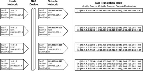 Using the example in Figure 3-13, which was discussed previously, the same sequence of events occurs but results in different translations because IP addresses are allocated in sequence from the pool. Port Address Translation (PAT)Besides using static or dynamic source IP address NAT to conserve registered IP addresses and hide internal resources, you can also use Port Address Translation (PAT). However, with PAT a single IP address serves multiple source IP addresses. Additionally, neither static nor dynamic source NAT rewrites the source port of the source TCP segments. In contrast, PAT rewrites the source transport port of the TCP or UDP segments in order to distinguish between NAT entries in the translation table. Figure 3-15 illustrates how the single IP 209.165.200.225 is used by three privately addressed computers to access an HTTP server on the outside network at 209.165.201.1. The source ports 6001, 6002, and 6003 are used by the NAT device in this example to distinguish the PAT entries in the translation table. In practice, the source port numbers chosen by a NAT device are generated randomly. Figure 3-15. A Port Address Translation Example Destination TranslationA less common form of NAT is destination NAT, which is used primarily by content switches to perform server and cache load balancing. With SLB, server farms containing real servers that are each assigned individual IP addresses share the incoming connections. The content switch rewrites the destination IP of a packet to one of the real server IPs and forwards the packet to the real server that is allocated that IP. In Figure 3-16, three sources from the public Internet (that is, the outside network) access an inside HTTP server using the virtual IP (VIP) 209.165.201.1. The three clients are addressed as follows:
Figure 3-16. A Destination NAT Example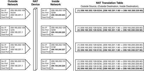 The four individual inside real servers that are accessed using the VIP 209.165.201.1 are addressed as follows:
Figure 3-16 illustrates the translations that take place when the three clients access the virtual IP. In the first two entries, the same user with IP address 209.165.202.129 accesses the HTTP server by opening two browsers to the main page, as in previous examples. But NAT now occurs on the destination address of the HTTP server. The NAT device allocates the next available IP in the pool, rewrites the destination IP address in the packet, and forwards the packet to the real server. Note Much more memory is required for destination NAT, because the sources are from the Internet and are not limited to the number of clients in your organization. |
EAN: 2147483647
Pages: 178