An Advanced BGP Configuration
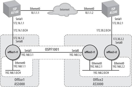
Figure 10-2 shows a network that consists of two offices connected to two different ISPs. The offices run OSPF between themselves and use BGP to exchange routes with the ISPs. The two offices are part of a single autonomous system, AS 3000. Each ISP has its own AS number (100 and 200). Office 1 has a single router, which takes care of all its needs. Office 2 has two routers: office2-r1 runs OSPF only and is responsible only for interior routing; office2-r2 provides the connection to the outside world through ISP2. On office1-r1, we need to configure eBGP to exchange routes with ISP1. Likewise, we must configure office2-r2 to exchange routes with ISP2. We want to implement a simple routing policy that prevents the ISPs from using our network to send packets to other autonomous networks. That is, we don't want transit traffic flowing through our sitewe want only traffic that is destined for our network.
Figure 10-2. BGP network with two service providers
The transit-traffic filtering is accomplished by using AS path filters , which we discussed in a previous section. On both routers, the filtering takes place in AS path access list 1. This is a simple access list: all we need to do is permit routes that originated within our local autonomous system. Our AS number happens to be 3000, but that's not important for writing the filterwe just need to realize that the regular expression ^$ matches routes that originated within our autonomous system, and no others.
Here's the configuration for office1-r1. It runs OSPF (process ID 1001) for communicating with the other office, and it sets up an eBGP connection to AS 100 (ISP1) and an iBGP connection to the office2-r2 router (AS 3000). The filter list that prevents transit traffic is applied to outbound updates destined for ISP1. If we don't tell ISP1 about any routes that don't originate from our own AS, ISP1 will be unable to route transit traffic through our network.
 hostname office1-r1
 !
 ! Configure our interfaces
 interface Ethernet0
 ip address 192.168.1.1 255.255.255.0
 !
 interface Serial0
 ip address 172.16.1.2 255.255.255.0
 !
 interface Serial1
 ip address 192.168.3.1 255.255.255.0
 clockrate 64000
 !
 ! We are running OSPF as our IGP
 router ospf 1001
 network 192.168.1.0 0.0.0.255 area 1
 network 192.168.3.0 0.0.0.255 area 0
 ! We want to tell other OSPF routers that we are the default router
 default-information originate
 !
 ! Our BGP configuration
 router bgp 3000
 no synchronization
 bgp dampening
 network 172.16.1.0
 ! Configuration for ISP1 with an outbound filter list. This list assures
 ! that we will announce only routes that originated within our AS
 neighbor 172.16.1.1 remote-as 100
 neighbor 172.16.1.1 filter-list 1 out
 ! Our neighbor office2-r2
 neighbor 192.168.2.2 remote-as 3000
 neighbor 192.168.2.2 next-hop-self
 no auto-summary
 !
 ! A static route is needed because we are advertising that we are the
 ! default route for the network, but we need to tell local route traffic
 ! where the default is for us. (Not required if you have a full routing
 ! table.)
 ip route 0.0.0.0 0.0.0.0 172.16.1.1
 !
 ! The following is a simple AS regular expression. This AS access
 ! list will permit only routes that originated within our AS
 ip as-path access-list 1 permit ^$
office2-r1 has a simple OSPF configuration:
 hostname office2-r1
 !
 interface Ethernet0
 ip address 192.168.2.1 255.255.255.0
 !
 interface Serial0
 ip address 192.168.3.2 255.255.255.0
 !
 ! Nothing new here
 router ospf 1001
 network 192.168.2.0 0.0.0.255 area 0
 network 192.168.3.0 0.0.0.255 area 0
The configuration for office2-r2 is similar to the configuration for office1-r1. Again, this router needs an OSPF process for interior routing. The process number is 1001, which matches the process number on the other routers. For BGP, we set up an eBGP connection to the ISP2 router (AS 200) and an iBGP connection to office1-r1 (AS 3000). The route filtering is identical.
 hostname office2-r2
 !
 interface Ethernet0
 ip address 192.168.2.2 255.255.255.0
 !
 interface Serial0
 ip address 172.30.2.2 255.255.255.0
 !
 router ospf 1001
 network 192.168.2.0 0.0.0.255 area 0
 default-information originate
 !
 router bgp 3000
 no synchronization
 bgp dampening
 network 172.30.2.0
 neighbor 172.30.2.1 remote-as 200
 neighbor 172.30.2.1 filter-list 1 out
 neighbor 192.168.3.1 remote-as 3000
 neighbor 192.168.3.1 next-hop-self
 no auto-summary
 !
 ip route 0.0.0.0 0.0.0.0 172.30.2.1
 !
 ip as-path access-list 1 permit ^$
To prove that our configuration works, we can do a show ip bgp from both office1-r1 and office2-r2. Here are the results:
 office1-r1#show ip bgp
 BGP table version is 50, local router ID is 192.168.3.1
 Status codes: s suppressed, d damped, h history, * valid, > best, i - internal
 Origin codes: i - IGP, e - EGP, ? - incomplete

 Network Next Hop Metric LocPrf Weight Path
 *> 172.16.0.0 172.16.1.1 0 0 100 i
 *>i172.30.0.0 192.168.2.2 0 100 0 200 I

 office2-r2#show ip bgp
 BGP table version is 3, local router ID is 192.168.2.2
 Status codes: s suppressed, d damped, h history, * valid, > best, i - internal
 Origin codes: i - IGP, e - EGP, ? - incomplete

 Network Next Hop Metric LocPrf Weight Path
 *>i172.16.0.0 192.168.3.1 0 100 0 100 i
 *> 172.30.0.0 172.30.2.1 0 0 200 i
This output shows that both routers recognize each other via BGP. The output of show ip route on office2-r2 also shows that the routes are there as expected:
 office2-r2#sh ip route
 Codes: C - connected, S - static, I - IGRP, R - RIP, M - mobile, B - BGP
 D - EIGRP, EX - EIGRP external, O - OSPF, IA - OSPF inter area
 N1 - OSPF NSSA external type 1, N2 - OSPF NSSA external type 2
 E1 - OSPF external type 1, E2 - OSPF external type 2, E - EGP
 i - IS-IS, L1 - IS-IS level-1, L2 - IS-IS level-2, * - candidate default
 U - per-user static route, o - ODR

 Gateway of last resort is 172.30.2.1 to network 0.0.0.0

 B 172.16.0.0/16 [200/0] via 192.168.3.1, 00:03:15
 172.30.0.0/16 is variably subnetted, 2 subnets, 2 masks
 C 172.30.2.0/24 is directly connected, Serial0
 B 172.30.0.0/16 [20/0] via 172.30.2.1, 00:03:06
 O IA 192.168.1.0/24 [110/84] via 192.168.2.1, 00:49:56, Ethernet0
 C 192.168.2.0/24 is directly connected, Ethernet0
 O 192.168.3.0/24 [110/74] via 192.168.2.1, 00:49:57, Ethernet0
 S* 0.0.0.0/0 [1/0] via 172.30.2.1
Finally, to make sure both links work, we can run a quick test on office2-r1. This test is limited, in that it really tests only our OSPF configuration, but it gives us more confidence that the network as a whole is running. First, show ip route on office2-r1 shows that it prefers office2-r2 as its default router:
 office2-r1#show ip route
 Codes: C - connected, S - static, I - IGRP, R - RIP, M - mobile, B - BGP
 D - EIGRP, EX - EIGRP external, O - OSPF, IA - OSPF inter area
 N1 - OSPF NSSA external type 1, N2 - OSPF NSSA external type 2
 E1 - OSPF external type 1, E2 - OSPF external type 2, E - EGP
 i - IS-IS, L1 - IS-IS level-1, L2 - IS-IS level-2, * - candidate default
 U - per-user static route, o - ODR

 Gateway of last resort is 192.168.2.2 to network 0.0.0.0

 O IA 192.168.1.0/24 [110/74] via 192.168.3.1, 00:08:06, Serial0
 C 192.168.2.0/24 is directly connected, Ethernet0
 C 192.168.3.0/24 is directly connected, Serial0
 O*E2 0.0.0.0/0 [110/1] via 192.168.2.2, 00:07:20, Ethernet0
If we shut down the serial0 link on office2-r2, show ip route on office2-r1 shows that it has recalculated its routes and selected office1-r1 as the default router:
 office2-r1#show ip route
 Codes: C - connected, S - static, I - IGRP, R - RIP, M - mobile, B - BGP
 D - EIGRP, EX - EIGRP external, O - OSPF, IA - OSPF inter area
 N1 - OSPF NSSA external type 1, N2 - OSPF NSSA external type 2
 E1 - OSPF external type 1, E2 - OSPF external type 2, E - EGP
 i - IS-IS, L1 - IS-IS level-1, L2 - IS-IS level-2, * - candidate default
 U - per-user static route, o - ODR

 Gateway of last resort is 192.168.3.1 to network 0.0.0.0

 O IA 192.168.1.0/24 [110/74] via 192.168.3.1, 00:08:48, Serial0
 C 192.168.2.0/24 is directly connected, Ethernet0
 C 192.168.3.0/24 is directly connected, Serial0
 O*E2 0.0.0.0/0 [110/1] via 192.168.3.1, 00:00:05, Serial0
10.4.1. Adding a Preference
Figure 10-2 shows a network with links to two different providers. We've already seen configurations that get the network up and running. Now, we would like to give one provider preference over the other for outbound traffic. Let's assume that ISP1 is more reliable so, whenever possible, we want to send our traffic over its network. To do this, we use a route map to modify the local preference metric so that we prefer routes to ISP1. Remember that the local preference metric stays local to our networkthat is, we never send the local preference outside of our ASbut is shared among the routers within our AS.
In office2-r2, we add a route map named CHANGE_LOCAL_PREF. This map sets the local preference for routes through ISP2 to 50, making ISP1 more preferable than ISP2. (The default local preference is 100, and higher preferences are better.) The configuration change means that even if we have to traverse our WAN link between the offices, we will use ISP1 rather than ISP2. Here are the changes to the configuration for office2-r2:
 ! While we're at it, we need to make sure OSPF picks the right ISP as
 ! well, so we'll increase the metric for the default route here
 ! to 1000.
 router ospf 1001
 network 192.168.2.0 0.0.0.255 area 0
 default-information originate metric 1000
 !
 ! In our BGP configuration, the only change is the addition of the route
 ! map for neighbor 172.30.2.1. Everything else is the same as it was
 ! before.
 router bgp 3000
 neighbor 172.30.2.1 route-map CHANGE_LOCAL_PREF in
 !
 ! Finally, we create our route map to change the local preference for
 ! neighbor 172.30.2.1
 route-map CHANGE_LOCAL_PREF permit 10
 set local-preference 50
show ip bgp on office2-r2 shows that the local preference for the route has indeed changed:
 office2-r2#show ip bgp
 BGP table version is 3, local router ID is 192.168.2.2
 Status codes: s suppressed, d damped, h history, * valid, > best, i - internal
 Origin codes: i - IGP, e - EGP, ? - incomplete

 Network Next Hop Metric LocPrf Weight Path
 *>i172.16.0.0 192.168.3.1 0 100 0 100 i
 *> 172.30.0.0 172.30.2.1 0 50 0 200 i
Finally, let's do a show ip route on office2-r1 and see which default route it prefers:
 office2-r1>show ip route
 Codes: C - connected, S - static, I - IGRP, R - RIP, M - mobile, B - BGP
 D - EIGRP, EX - EIGRP external, O - OSPF, IA - OSPF inter area
 N1 - OSPF NSSA external type 1, N2 - OSPF NSSA external type 2
 E1 - OSPF external type 1, E2 - OSPF external type 2, E - EGP
 i - IS-IS, L1 - IS-IS level-1, L2 - IS-IS level-2, * - candidate default
 U - per-user static route, o - ODR

 Gateway of last resort is 192.168.3.1 to network 0.0.0.0

 O IA 192.168.1.0/24 [110/74] via 192.168.3.1, 01:51:25, Serial0
 C 192.168.2.0/24 is directly connected, Ethernet0
 C 192.168.3.0/24 is directly connected, Serial0
 O*E2 0.0.0.0/0 [110/1] via 192.168.3.1, 01:40:24, Serial0
Getting Started
- Getting Started
- IOS User Modes
- Command-Line Completion
- Get to Know the Question Mark
- Command-Line Editing Keys
- Pausing Output
- show Commands
IOS Images and Configuration Files
- IOS Images and Configuration Files
- IOS Image Filenames
- The New Cisco IOS Packaging Model
- Loading Image Files Through the Network
- Using the IOS Filesystem for Images
- The Routers Configuration
- Loading Configuration Files
Basic Router Configuration
- Basic Router Configuration
- Setting the Router Name
- Setting the System Prompt
- Configuration Comments
- The Enable Password
- Mapping Hostnames to IP Addresses
- Setting the Routers Time
- Enabling SNMP
- Cisco Discovery Protocol
- System Banners
Line Commands
- Line Commands
- The line Command
- The Console Port
- Virtual Terminals (VTYs)
- Asynchronous Ports (TTYs)
- The Auxiliary (AUX) Port
- show line
- Reverse Telnet
- Common Configuration Items
Interface Commands
- Interface Commands
- Naming and Numbering Interfaces
- Basic Interface Configuration Commands
- The Loopback Interface
- The Null Interface
- Ethernet, Fast Ethernet, and Gigabit Ethernet Interfaces
- Token Ring Interfaces
- ISDN Interfaces
- Serial Interfaces
- Asynchronous Interfaces
- Interface show Commands
Networking Technologies
Access Lists
IP Routing Topics
- IP Routing Topics
- Autonomous System (AS) Numbers
- Interior and Exterior Gateway Protocols
- Distance-Vector and Link-State Routing Protocols
- Static Routes
- Split Horizon
- Passive Interfaces
- Fast Switching and Process Switching
Interior Routing Protocols
Border Gateway Protocol
- Border Gateway Protocol
- Introduction to BGP
- A Simple BGP Configuration
- Route Filtering
- An Advanced BGP Configuration
- Neighbor Authentication
- Peer Groups
- Route Reflectors
- BGP Confederacies
- BGP TTL Security
Quality of Service
- Quality of Service
- Marking
- Older Queuing Methods
- Modern IOS QoS Tools
- Congestion Avoidance
- Traffic Policing
- Traffic Shaping
- AutoQoS
- QoS Device Manager
Dial-on-Demand Routing
- Dial-on-Demand Routing
- Configuring a Simple DDR Connection
- Sample Legacy DDR Configurations
- Dialer Interfaces (Dialer Profiles)
- Multilink PPP
- Snapshot DDR
Specialized Networking Topics
- Specialized Networking Topics
- Bridging
- Hot Standby Routing Protocol (HSRP)
- Network Address Translation (NAT)
- Tunnels
- Encrypted Tunnels
- Multicast Routing
- Multiprotocol Label Switching (MPLS)
Switches and VLANs
- Switches and VLANs
- Switch Terminology
- IOS on Switches
- Basic Switch Configuration
- Trunking
- Switch Monitor Port for IDS or Sniffers
- Troubleshooting Switches
Router Security
- Router Security
- Securing Enable Mode Access
- Routine Security Measures
- Restricting Access to Your Router
Troubleshooting and Logging
Quick Reference
Appendix A Network Basics
Index
EAN: 2147483647
Pages: 1031
