MEMORY PACKAGING
We have discussed memory types and how they function. Now we will focus on how memory is packaged together and attached to the motherboard.
A DRAM chip is considered one unit or a single chip. When several DRAM chips are soldered onto a circuit board, a bank of chips is formed. The combination of DRAM chips soldered onto the circuit board makes up a memory module or memory package. The memory modules are inserted into the motherboard to form rows of memory banks. There are several types of memory modules, each of which has its own characteristics and design.
Pay very close attention to the packaging methods discussed in this chapter. The A+ Core Hardware Service Technician test is very likely to test your knowledge on memory modules, including SIMMs, DIMMs, RIMMs, SODIMMs, and MicroDIMMs. You will likely be shown a graphic and be asked to describe the memory module being displayed. See Table 17.3 for a quick reference on memory modules.
| Module Type | Number of Pins | Memory Bus Width |
|---|---|---|
| SIMM | 30 pins | 8 bits |
| SIMM | 72 pins | 32 bits |
| DIMM | 168 pins | 64 bits |
| RIMM | 184 pins | 16 bits (or 2 bytes wide) |
| SODIMM | 72 pins | 32 bits |
| SODIMM | 144 pins | 64 bits |
| MicroDIMM | 144 pins | 64 bits |
Gold and Tin Edge Connectors
SIMMs and DIMMs both have edge connecters (or leads) that are pushed into the motherboard’s memory slots. These edge connectors come in two distinct forms: tin (silver colored) and gold colored. There is not much of a difference between the two forms, but it is very important that the color of the connector match the color of the inside of the motherboard’s memory slot. The inside of the motherboard’s memory slot is either gold or tin. In short, match the gold-edged SIMM or DIMM connector to the gold memory slot on the motherboard. Match the tin (silver-colored) edge connector to the silver-colored memory slot on the motherboard. The two different metal forms have different chemical compositions; a mismatch in color may result in corrosion and eventually cause the system to fail or become unbootable.
Single Inline Memory Module (SIMM)
A SIMM is a memory module that has either a 30-pin or 72-pin edge connector that inserts into the motherboard memory sockets at a 45 angle. A 30-pin SIMM (Figure 17.1) has DRAM chips soldered onto one side of its circuit board. Older, 30-pin SIMMs used FPM technology and generally came in sizes of 256K to 4MB, with an 8-bit memory bus width. The newer 72-pin SIMMs use EDO technology and come in sizes ranging from 1MB to 128MB, with a 32-bit bus width. A 72-pin SIMM (Figure 17.2) can have DRAM chips soldered on one or both sides of the circuit board. As you learned earlier in this chapter, memory speed is measured in nanoseconds. Most SIMMs run at 60ns, 70ns, or 80ns.
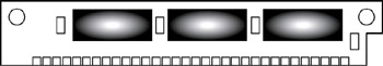
Figure 17.1: A 30-pin SIMM (memory module).
![]()
Figure 17.2: A 72-pin SIMM (memory module).
Dual Inline Memory Module (DIMM)
Systems that provided 64-bit or wider memory buses opened the door for the DIMM. Most modern computers provide memory slots on the motherboard that support the 168-pin DIMM memory module (Figure 17.3). A DIMM is larger than a SIMM and has an additional set of leads that make it impossible to install the DIMM improperly. DIMMs come in different voltages (3.3V and 5.0V) and are available in buffered or unbuffered form. When purchasing new DIMMs, you should consult the motherboard manufacturer’s guide.
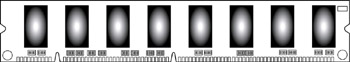
Figure 17.3: A 168-pin DIMM (memory module).
Small-Outline Dual Inline Memory Module (SODIMM)
A SODIMM is a smaller DIMM that was specifically designed for laptop computers. There are two major types of SODIMMs. They come on a module that has 72 pins with a transfer rate of 32 bits or a module with 144 pins at a transfer rate of 64 bits (Figure 17.4).
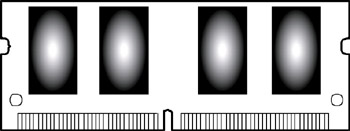
Figure 17.4: A small-outline dual inline memory module (SODIMM).
The following Crucial Technologies Web site has a great PDF document that explains how to properly install a SODIMM in a laptop computer system: http://images.crucial.com/pdf/sodimm_install.pdf.
Micro Dual Inline Memory Module (MICRODIMM)
MicroDIMMs are memory modules that are often used in subnotebook computers. They have 144 pins and provide a 64-bit data path (Figure 17.5).
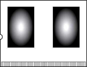
Figure 17.5: A micro dual inline memory module (MicroDIMM).
The following TransmetaZone Web site provides a great demonstration regarding the installation of a 128MB, 144-pin MicroDIMM. http://www.transmetazone.com/articleview.cfm?articleid=1195&page=4.
RIMM
Trademarked by Kingston Technology Corp., a RIMM is a memory module that uses RDRAM chips. A RIMM uses a special circle-like technology that rotates data in a unidirectional, looped system between the RIMM modules and special blank memory banks called continuity RIMMs (C-RIMMs) that must be placed between RIMMs. This looping system eliminated the bottleneck that resulted from DRAM and its bidirectional bus, which caused data to wait before being sent down a row of memory modules. A RIMM is physically smaller than a DIMM and uses a different pin configuration. Noticeably, a RIMM uses a 184-pin connector (Figure 17.6).
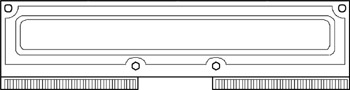
Figure 17.6: A rambus inline memory module (RIMM).
If you want to know more about RIMM technology, visit the Kingston Technology Web site at: http://www.kingston.com/newtech/rambusarch.asp.
Installing SIMMS, DIMMS, and RIMMS
There was a time when installing memory modules into a computer could be very painful on your fingers. Older motherboards did not have the clip and spring features supported by today’s motherboard memory slots, which allow the memory modules to be easily pushed into place.
Here are the basic steps for installing SIMMs, DIMMs, and RIMMs into your computer.
-
Unplug power to the computer.
-
Remove the system unit case cover.
-
Make sure you are wearing an ESD wrist strap.
-
Identify the SIMM or DIMM slots.
-
With both hands, line up the SIMM, DIMM, or RIMM with the open motherboard memory slot.
-
Push firmly on both sides of the SIMM, DIMM, or RIMM until it is seated in the slot. (SIMMs should be inserted into the motherboard at a 45 angle.)
-
Replace the system unit case.
-
Take off your ESD wrist strap.
-
Plug the power cord back into the computer and turn the computer on.
In newer computers, you will see that the new memory has been added when the POST runs its memory count. Your memory will be automatically configured. In older systems, you may have to make changes to your memory settings in the system BIOS configuration utility before the new memory is recognized.
When installing or adding memory to a memory bank, you should avoid mixing different types of memory modules together. You can mix different speeds of memory within the same memory bank. However, the speed of the slowest module within a bank of RAM will become the speed used by the system.
-
SIMMs should be installed in increments of two or four memory modules per memory bank.
-
DIMMs can be installed in units of one (one module) per memory bank.
-
RIMMs should be installed in pairs and be the same size, type, and speed. If you fail to match paired memory modules, your system may not boot, or you may receive a POST error.
Note It is very likely that the exam will present you with a graphic display of a memory module and ask you to identify it by name. You should know what all the memory modules mentioned in this chapter physically look like, or there is a good chance you will find yourself counting pins on the test display screen!
CompactFlash
CompactFlash is a type of memory card that depends on flash memory. CompactFlash is commonly used in devices such as PDAs, pocket PCs, and digital cameras. They are smaller than a regular PC card and can be easily used with a special adapter in Type I and Type II PC card slots.
CompactFlash technology has also become very popular in the wireless world. In fact, 11Mbps wireless CompactFlash network cards are available everywhere, and connecting your PDA, pocket PC, or other devices to a network is now easy and hassle free.
EAN: 2147483647
Pages: 390
- Structures, Processes and Relational Mechanisms for IT Governance
- Assessing Business-IT Alignment Maturity
- Measuring and Managing E-Business Initiatives Through the Balanced Scorecard
- Technical Issues Related to IT Governance Tactics: Product Metrics, Measurements and Process Control
- The Evolution of IT Governance at NB Power