| The PA-RISC architecture provides for several sets of registers. Of particular interest to us are the general registers, space registers, and some of the control registers. General Registers PA-RISC has 32 general purpose registers. In PA-RISC 2.0, these are 64-bit registers; prior to PA-RISC 2.0, these registers are 32 bits wide. The architecture itself defines specific uses for only a few of these registers: GR0 Permanent zero. Reads from this register always return a zero. Writes to this register are discarded. GR1 Target of ADDIL. When the ADD IMMEDIATE LONG (ADDIL) instruction is executed, the result is always placed in GR1. This register can also be used for other purposes. GR2 Target of B,L. This register is used as the target of the BRANCH AND LINK instruction, which is used for procedure calls. The link, or return, address is placed in GR2. This register can also be used for other purposes. GR31 Target of BLE. This register is similar to GR2 but is used for the return address from a BRANCH AND LINK EXTERNAL instruction.
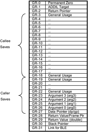
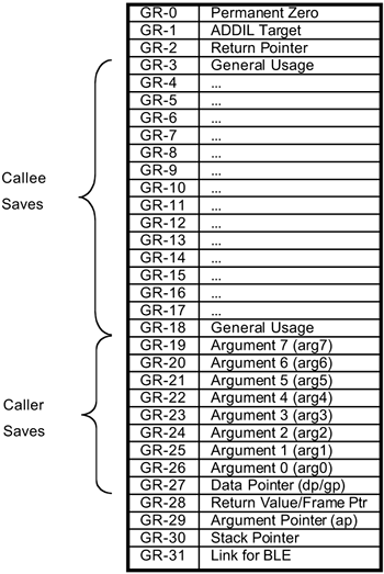
Beyond these requirements there is also a software convention that specifies how registers will be used by HP-UX. These conventions are slightly different for the 64-bit version of HP-UX. Figure 1-2 shows the usage of general registers for the 32-bit kernel, and Figure 1-3 shows the usage for the 64-bit kernel. Most of these requirements for register usage come into play when performing procedure calls and are covered in detail in Chapter 2, "Procedure Calling Conventions." GR27, the data pointer, points to the base of the data segment. Memory references to the data segment are made relative to GR27. These are primarily global values in the kernel. GR30 is the stack pointer. Figure 1-2. 32-Bit General Registers 
Figure 1-3. 64-Bit General Registers 
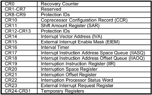
Space Registers PA-RISC provides eight space registers. As with the general registers, the architecture provides for 64-bit wide registers on PA-RISC 2.0 and 32-bit wide registers on PA-RISC 1.1. However, on all current implementations of PA-RISC 2.0, the space registers are actually only 32 bits wide. The space registers are used in combination with the general registers to construct a virtual address. The space register can be either explicitly supplied in the instruction or implied by the value in the general register. The use of the space registers is covered in detail in the section "Virtual Memory Support." Control Registers PA-RISC provides 32 control registers (see Figure 1-4). Again, in PA-RISC 1.1 these are 32-bit registers, and in PA-RISC 2.0 they are 64-bit registers. Most of these are used when handling interruptions and are discussed in detail in the section "Interruption Handling." Figure 1-4. Control Registers 
Processor Status Word One more register of interest is the Processor Status Word (PSW). This is a 64-bit register (32-bits on PA-RISC 1.1) whose bits indicate the state of the system. Some of these bits are controlled explicitly by the kernel, and others are set implicitly as the result of some action such as an interruption or taken branch. Table 1-1, from Gerry Kane's PA-RISC 2.0 Architecture, lists the bits in the PSW and their meanings. Table 1-1. Processor Status Word BitsField | Description |
|---|
W | Wide 64-bit address formation enable. When 1, full 64-bit-offset addressing is enabled. When 0, addresses are truncated to 32-bit offsets for compatibility with existing PA-RISC 1.0 and 1.1 applications. | E | Little endian memory access enable. When 0, all memory references are big endian. When 1, all memory references are little endian. Implementation of this bit is optional. If it is not implemented, all memory references are big endian and this bit is a reserved bit. | S | Secure Interval Timer. When 1, the Interval Timer is readable only by code executing at the most privileged level. When 0, the Interval Timer is readable by code executing at any privilege level. | T | Taken branch trap enable. When 1, any taken branch is terminated with a taken branch trap. | H | Higher-privilege transfer trap enable. When 1, a higher-privilege transfer trap occurs whenever the following instruction is of a higher privilege. | L | Lower-privilege transfer trap enable. When 1, a lower-privilege transfer trap occurs whenever the following instruction is of a lower privilege. | N | Nullify. The current instruction is nullified when this bit is 1. This bit is set to 1 by an instruction that nullifies the following instruction. | X | Data memory break disable. The X-bit is set to 0 after the execution of each instruction, except for the RETURN FROM INTERRUPTION instruction, which may set it to 1. When 1, data memory break traps are disabled. This bit allows a simple mechanism to trap on a data store and then proceed past the trapping instruction. | B | Taken branch. The B-bit is set to 1 by any taken branch instruction and set to 0 otherwise. This is used to ensure that the BRANCH instruction with the,GATE completer (the privilege-increasing instruction) cannot be used to compromise system security. | C | Code (instruction) address translation enable. When 1, instruction addresses are translated and access rights checked. | V | Divide step correction. The DIVIDE STEP (integer division primitive) instruction records intermediate status in this bit to provide a nonrestoring divide primitive. | M | High-priority machine check mask. When 1, high-priority machine checks (HPMCs) are masked. Normally 0, this bit is set to 1 after an HPMC and set to 0 after all other interruptions. | C/B | Carry/borrow bits. The following instructions update the PSW carry/borrow bits from the corresponding carry/borrow outputs of the 4-bit digits of the ALU: ADD* ADDI DS
SHLADD* SUB SUBI The instructions marked with an asterisk set the carry/borrow bits only if the L (logical) completer is not specified. After an add which sets them, each bit is set to 1 if a carry occurred out of its corresponding digit and set to 0 otherwise. After a subtract which sets them, each bit is set to 0 if a borrow occurred into its corresponding digit, and set to 1 otherwise. Bits {24..31} hold the digit carries from the upper half of the ALU, and bits {48..55} hold the digit carries from the lower half. | O | Ordered references. When 1, virtual memory references to pages with the corresponding TLB O-bit 1 and all absolute memory references are ordered. When 0, memory references (except those explicitly marked as ordered or strongly ordered) may be weakly ordered. Note that references to I/O address space, references to pages with the TLB U-bit 1, semaphore instructions, and TLB purge instructions are always strongly ordered. | F | Performance monitor interrupt unmask. When 1, the performance monitor interrupt is unmasked and can cause an interruption. When 0, the interruption is held pending. Implementation of this bit is required only if the performance monitor is implemented and the performance monitor has the ability to interrupt. If it is not implemented, this bit is a reserved bit. | R | Recovery Counter enable. When 1, recovery counter traps occur if bit 0 of the recovery counter is a 1. This bit also enables decrementing of the recovery counter. | Q | Interruption state collection enable. When 1, interruption state is collected. Used in processing the interruption and returning to the interrupted code, this state is recorded in the Interruption Instruction Address Queue (IIAQ), the Interruption Instruction Register (IIR), the Interruption Space Register (ISR), and the Interruption Offset Register (IOR). | P | Protection identifier validation enable. When this bit and the C-bit are both equal to 1, instruction references check for valid protection identifiers (PIDs). When this bit and the Dbit are both equal to 1, date references check for valid PIDs. When this bit is 1, probe instructions check for valid PIDs. | D | Data address translation enable. When 1, data addresses are translated and access rights checked. | I | External interrupt, power failure interrupt, and low-priority machine check interruption unmask. When 1, these interruptions are unmasked and can cause an interruption. When 0, the interruptions are held pending. |
|