6.2 Graphical User Interface (GUI) Design and Prototyping (UI ControllerMessage Queue Pattern)
6.2 Graphical User Interface (GUI) Design and Prototyping (UI Controller>>Message Queue Pattern)
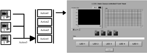
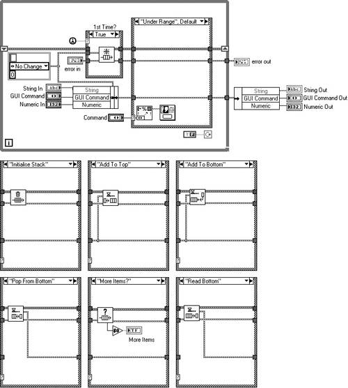
Most of us initially have problems with UI implementation and controls in LabVIEW. They can end up having large, flat block diagrams or the use of globals (elegant, but a coupling and information hiding no-no). Some LabVIEW gurus suggest using globals as the only way to program complex LabVIEW UIs. They are WRONG! This section will demonstrate how you can view your Front Panel as a container of Controls that have Attributes and Actions associated with them. It would be nice if these Attributes and Actions could be triggered from anywhere in your applications hierarchy. Well, why not pass them as messages in a queue. Then, on your Front Panel you could read these items off the queue and respond to them. This is classic message sending. In effect, you are changing your UI into a state machine and queuing its new states. Figure 6.7 demonstrates this queuing mechanism.
Figure 6.7. UI control example.
Let's run through an example.
The Front Panel in Figure 6.8 is a simple demonstration of the principles discussed above. We will populate it with a few Indicators and Controls and then control them by queuing messages.
Figure 6.8. LCOD User Interface example.
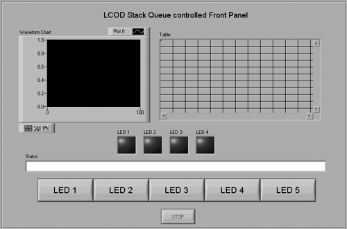
Either the graph or the table will be visible depending on the graph/table button condition as shown in Figure 6.8. Pressing the LED buttons will toggle the corresponding LED. In the background, the status string updates. This User Interface has minimal complexity, but you could add 10 times the complexity without changing the program structure markedly.
A list of what you want to do to it is shown in Figure 6.9.
Figure 6.9. User Interface actions.
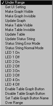
As you can see, the UI states have already been typed into an enumerated type, allowing us to edit and remove items at will. Just pop up on the enumerated type and add the new function, its attributes, and update the UI control VI.
This is something you could sit down with your customer and define.
This enumerated type becomes the command for the wrapper VI that passes all the messages into the queue (UI Control.vi).
6.2.1 Stack Queue Component
This little component, shown in Figure 6.10, is useful for many purposes. We tend to adapt it the most for Front Panel control, background filing, and database work. Figures 6.11, 6.12, 6.13 and 6.14 demonstrate how it functions.
Figure 6.10. Stack queue component connector.
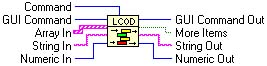
Figure 6.11. Stack.
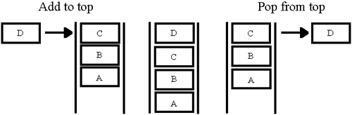
Figure 6.12. Upside-down stack.
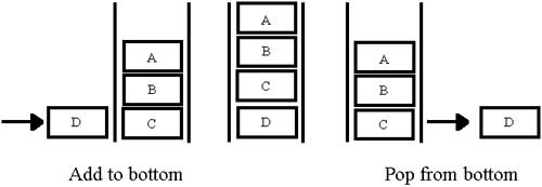
Figure 6.13. Queue.
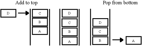
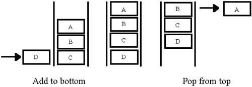
Figure 6.14. Upside-down queue.
There are also several useful utilities for reading the top and bottom and checking if the component is empty. Here is the implementation in LabVIEW 6.
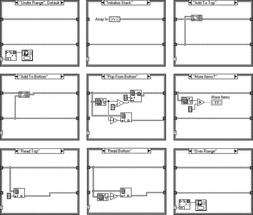
Selecting "Add to Top" or "Add to Bottom" on the enumerated type "GUI Command" shown in Figure 6.15, will pass the data into Array Local, either at the beginning or end of the array. You then have the option of taking this data from the beginning or end of the array with the commands "Pop from Top" or "Pop from Bottom". Figures 6.16 and 6.17 show its implementation.
Figure 6.15. Stack queue Front Panel.
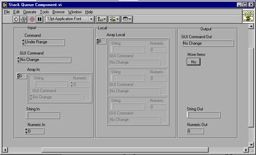
Figure 6.16. Stack queue diagram.
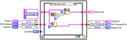
Figure 6.17. Stack queue cases.
It's relatively easy to modify the component to your own data requirements by changing the inputs, clusters, and array contents to suit. Make sure that the source code is left the same though.
We'll use this component to store and transmit the states of the User Interface.
The stack queue component works fine for small queues, but if you want to beef up the performance you could try using the queue VIs that come with LabVIEW. In LabVIEW 6.1, NI very kindly made them polymorphic and they work nicely , giving a significant performance improvement. We rewrote the component to include these VIs and they were about eight times as fast for large queues (2,000+ elements).
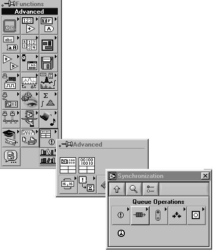
How to get to the queue functions can be found in Figure 6.18.
Figure 6.18. Queue operations.
We've kept the functionality and the interface similar, although there are now error clusters in and out. You can only take items from the end of the queue ”a small sacrifice for the speed advantage. The element cluster is a strict type def, therefore, to reuse the queue all you have to do is customize the element cluster. This can be done using the queue VIs in earlier versions of LabVIEW, but you have to squish the data to a string and unsquish it afterwards. Also you lose the ability to use the component like a stack, the queue functions constrain you to queuing in one end and out the other.
The source code for this implementation is in Figure 6.19.
Figure 6.19. LV6.1 stack queue component diagram.
6.2.2 User Interface Control Wrapper VI
Next you have to create the wrapper component that conducts all the actions on the stack. For improved maintenance you could map the input command directly to the "GUI Command Out", but this has a negative effect on the flexibility of the design. Figures 6.20, 6.21, and 6.22 describe the implementation for this VI.
Figure 6.20. UI Control.vi.
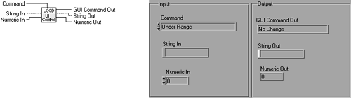
Figure 6.21. UI control diagram.
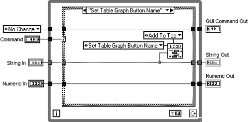
Figure 6.22. UI control cases.
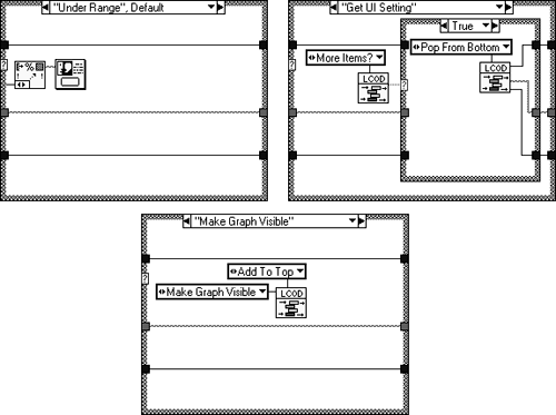
Looking at Figure 6.21 you can see the case for the display state, "Set Table Graph Button Name ". When this command is selected and the VI executed the corresponding command and string are placed in the queue. A loop in the UI block diagram is then responsible for pulling the commands and settings off the queue and executing them. The case, "Get UI Setting" in Figure 6.22 is responsible for this.
Adding a new User Interface attribute or action is merely a matter of updating the enumerated type, duplicating the case, and changing the enumerated type in the case to suit.
6.2.3 LCOD User Interface Example Diagram
Now put in the state machines for monitoring User Interface updates and checking for button presses. You will also notice in Figure 6.23 that everything is enclosed in another state machine that describes the states for the User Interface (initialize, run, finish).
Figure 6.23. LCOD Front Panel diagram.
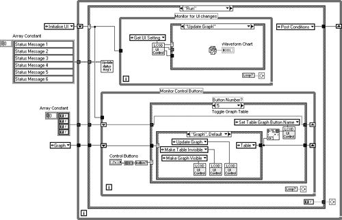
You then fill out the "Monitor for UI Changes" state machine for all of the attribute settings and actions as shown in Figure 6.24.
Figure 6.24. UI attributes and actions.
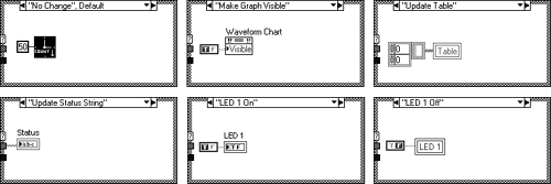
As you can see, all the attributes and actions for the User Interface are held in a nicely documented case structure. Adding more functionality is just a matter of creating another pigeonhole and placing the control or property node into it.
You can also make a small test stub VI that pushes actions onto the queue, allowing you to test each individual display setting. Just drop the UI Control into a new VI and set each input as a control. Run your User Interface and on the test stub select the action you require and run the test stub. As if by magic, the UI will do your bidding.
| |
| Top |
EAN: 2147483647
Pages: 66
- Understanding SQL Basics and Creating Database Files
- Using SQL Data Manipulation Language (DML) to Insert and Manipulate Data Within SQL Tables
- Using Data Control Language (DCL) to Setup Database Security
- Using Keys and Constraints to Maintain Database Integrity
- Repairing and Maintaining MS-SQL Server Database Files