Plane Collisions
Closest Point-to-Plane
Similar to the linear feature collision section, we will first examine a “closest point to” technique that will be the foundation for the plane collision set.
Given Plane and Test Point:
Plane normal = N
Plane point = Ppt
Test point = Tpt
See Figure 16.15.
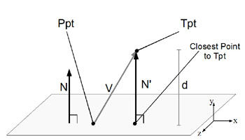
Figure 16.15: Closest point to the plane.
First, create the vector from plane point Ppt to the test point Tpt.
V = Cpt – Ppt
Next, compute the vector projection of vector V onto N.
Let d = the dot product of vectors N and V, and then scale N by d.
N' = N(N dot V))
Finally, subtract N' from test point to find the test point projected on to the plane:
Closest Point to Tpt: ProjPt = Tpt – N'
Sphere-to-Plane
Sphere-to-plane is one of the most useful tests in 3D games. It allows a volume object to test against a flat surface, which is an excellent approximation to many game collision situations. Also, when the required data is built into the game geometry and readily available, this is not only one of the cheapest collisions to compute but also one of the easiest types for which to create simply collision reaction.
Given: Plane and Test Sphere:
Plane normal = N
Plane point = Ppt
Sphere center = Cpt
Sphere radius = R
See Figure 16.16.
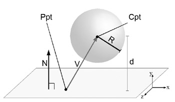
Figure 16.16: Sphere-to-plane test—no collision.
First, create a vector from the plane point Ppt to the sphere center point Cpt.
V = Cpt – Ppt
Next, compute the dot product of vectors N and V. As was explained in point-to-cylinder collision, when N is normalized the value of d is equal to the distance along vector N of vector V’s projection. Because N is perpendicular to the plane, d is also the distance to the plane from the sphere center point Cpt. Because of this fact, d can be compared to the sphere radius to find possible collision. If d is greater than R, no collision occurred.
d = N dot V
if ( d > R ) { return false; } // no collision
However, if d is less than R, then collision has occurred.
If ( d < R ) then collision has occurred.
If this is all that is desired to know for a particular routine, quitting here is fine. However, often sphere-to-plane collision tests are used to represent characters or objects colliding with world geometry, and simply detecting this is not enough. We want these objects to be moved out of collision with the plane, which is quite simple to do.
Simple Collision Reaction
To correct the sphere’s position from the plane collision, the sphere center must be moved away from the plane. The direction would be along the normal, and the magnitude would be R – D. To make this displacement vector, simply create vector N' = scale N by R – D.
N' = (N)R – D
Finally, add N' to the original sphere center and put it back into the sphere.
Cpt' = Cpt + N'
See Figure 16.17.
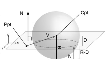
Figure 16.17: Sphere-to-plane test—collision occurred.
Ray/Segment-to-Triangle
The Ray/Segment-to-triangle test (see Figure 16.18) is a fundamental collision test in games using 3D geometry. Not only can it be used to represent weapons’ projectile travel path against world, object, and player geometry, it can be used for picking and AI line-of-sight testing, as well as an accurate fallback test for any other bounds collision test.
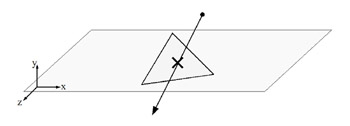
Figure 16.18: Line segment-to-triangle intersection.
Segment/ray-to-triangle is the most complex and most expensive collision test covered in this chapter. Thus, it will be broken into three stages, each containing collision tests generally useful beyond the use of this segment-to-triangle test.
Given: Line Segment and Triangle:
Triangle/Plane normal = N
Triangle/Plane point = Ppt
Line segment startpoint = P0pt
Line segment endpoint = P1pt
Line direction vector = L = (P1-P0)
The three steps are as follows:
-
Quickly reject all segments above and below the plane of the given triangle.
-
Calculate the intersection point of the line of the ray or segment, and the plane of the triangle.
-
Determine if the point of intersection falls within the given triangle.
These three steps can generate four possible cases, as seen in Figure 16.19.
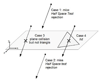
Figure 16.19: Line segment-to-triangle rejection cases.
3D Half-Space Test
To quickly reject segments above and below the plane we will use what is known as a half-space test. In particular this will be the general 3D half-space test and was actually performed earlier in the ray-to-sphere test but was not formalized until now. See Figure 16.20.
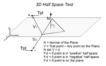
Figure 16.20: The 3D half-space test.
The test goes as follows:
Given: Test point and Plane:
N = Normal of the Plane
Ppt = Any point on the Plane
V = Test point
Create vector from any plane point Ppt to the test point Tpt.
V = Cpt – Ppt
Next, compute the dot product of vectors N and V:
N dot V = d
For a half-space test we say that the test point falls on one side or the other of a given plane by the following convention:
If d > 0, then the test point is in “positive” half-space
If d < 0, then the test point is in “negative” half-space
If d = 0, then the test point is on the plane
Used in the line segment-to-triangle test, we perform two 3D half-space tests, one for each of the line segments endpoints. If they are both on the same side of the plane, then the line segment does not cross the plane and there is no collision.
If the line segment’s endpoints are not on the same side, then the line segment crosses the plane and there is a guaranteed intersection point. If we wish only to detect line segment-to-plane collision, we could quit now; however, for triangle, we must test further.
Segment-to-Plane Intersection
Computing the intersection point is the most costly part of this algorithm but is often unavoidable, even in cases where the final point in the triangle test fails. The process is essentially computing a ratio between the length of the line segment along the normal to the distance between the line segment start point and the plane. This ratio will be between 0.0 and 1.0, and it describes the scale of the line segment’s direction vector (endpoint–start point) that would be at the point of intersection.
For example, if the ratio is 0.0, the intersection point would be at the line segment’s start point. If the ratio is 1.0, then the intersection would be at the line segments’ endpoint, or start point + ratio scale L (see Figure 16.22).
This can also be described and solved algebraically using the standard plane equation. We have provided the vectorial and algebraic solutions, where d is the ratio solution that must be applied back to the line segment to compute the final point.
Plane eq. Ax + By + Cz + D = 0,
where N{A,B,C},
Ppt{x,y,z}
D = – (Ax + By + Cz)
Parametric Line eq. P(d) = Po + dL
where x = Px + dLx
y = Py + dLy
z = Pz + dLz
Solving both equations for d yields Figure 16.21.
![]()
Figure 16.21: Line-to-plane intersection equation.
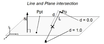
Figure 16.22: Line-and-plane intersection.
Compute d, then place d back in the parametric line equation to get final line segment-to-plane intersection point:
P(intersect) = P0 + d(L)
Point-to-2D Triangle
Last, we must determine if the intersection point lies within the given triangle. It turns out for this step that we can fall back to working in 2D for a quick solution. The 3D triangle and intersection point can be projected into 2D, and a 2D point-in-triangle test can be done, if we choose the right projection. The trick is to pick the right set of 2 “D”s from the 3D of x, y, z.
For example, we cannot simply always pick x, z (ignoring the y-coordinate, effectively that projection of the system to the ground) because the given triangle could be aligned perpendicular to the x-z-plane, in which case the 3D triangle would degenerate into a line segment.
Instead, we need to pick the projection in such as way that the triangle stays a triangle, no matter how it was oriented before projection.
It turns out that the solution is quite simple and lies in the triangle’s/planes’ normal. The normal can tell us about the orientation of the triangle, and, in fact, a quick check will guide us to the right projection. It works like this: whichever component of the triangle’s normal that has the greatest absolute value—x, y, or z—that is the dimension that can be dropped to make the 2D projection.
Another quick example will explain this better. If the given normal is straight up, it would have the components (0, 1, 0). In that orientation the triangle is lying perfectly flat already, but we can see that the y-components could be dropped, and the 3D triangle would become a 2D triangle without degenerating into a line segment.
Now, if by the same rule the normal was tilted, say, pointing at (0.8, 0.6, 0.0), we would drop the x-components from our test, and the final 2D triangle would now be parallel to the y-z-plane.
After the ignored dimensional component has been chosen, we perform the point-in-2D triangle test, which involves a series of simple 2D half-space tests for each of the triangle’s edges. To do these half-space tests, we need an edge normal, which normally (no pun intended) a triangle would not have. Luckily, because we are now working in 2D, there is a easy trick to get a vector perpendicular—just swap the vector components and make one of them negative.
N<x,y> is perpendicular to N<y,–x> and N<–y,x>:
With that little trick in hand, here’s the complete test assembled, as shown in Figure 16.23.
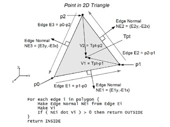
Figure 16.23: Line-and-plane intersection.
For each edge i in polygon { Make Edge Normal NEi from Edge Ei Make Vi If ( NEi dot Vi ) > 0 then return OUTSIDE } return INSIDE EAN: 2147483647
Pages: 171
- Enterprise Application Integration: New Solutions for a Solved Problem or a Challenging Research Field?
- The Effects of an Enterprise Resource Planning System (ERP) Implementation on Job Characteristics – A Study using the Hackman and Oldham Job Characteristics Model
- Distributed Data Warehouse for Geo-spatial Services
- Healthcare Information: From Administrative to Practice Databases
- Relevance and Micro-Relevance for the Professional as Determinants of IT-Diffusion and IT-Use in Healthcare