6.1 Ethernet and TCPIP
6.1 Ethernet and TCP/IPMainstream data communications networks are based on Ethernet for physical transport and on TCP/IP for routing of data from source to destination. Ethernet and TCP/IP are paired technologies for LAN and MAN (metropolitan area network) networks, whereas IP can extend to wide area networks over point-to-point, frame relay, ATM, Packet over SONET, or switched optical networks. Because the vast majority of organizations use Ethernet and IP for data communications, the introduction of shared storage based on Fibre Channel is often outside the scope of corporate IT network strategies. IP storage resolves this exclusion by bringing block storage data back into mainstream IP networking. Both Ethernet and TCP/IP have undergone substantial metamorphosis over the past 20 years. Ethernet began as a shared media access method over thick coaxial cable. IP began as a military-funded routing protocol that could still deliver messages even if parts of the network were blown to smithereens by nuclear attack. Twenty years later, Ethernet is now a switched physical transport that has little need for its original collision detection algorithm. And IP is now driving the Internet, the world's largest civilian network. Along this evolutionary path, other contenders for network transports and protocols proved unfit to survive. Those with proprietary sponsorships, such as Token Ring and SNA (Systems Network Architecture), eventually succumbed to the growing customer demand for open, interoperable systems. Today, Ethernet and TCP/IP are ubiquitous. This mass of installed base generates its own gravitational momentum, making it difficult for other technologies to secure an independent foothold among customers. For SANs, the convergence of Fibre Channel and IP technologies is already under way. 6.1.1 Gigabit Ethernet TransportFor data center applications, current-generation Ethernet is based on gigabit and 10Gbps switched networks. Gigabit Ethernet switches provide 1Gbps full duplex links to end devices and may support 10Gbps interswitch links to build a high-performance core infrastructure. Typically, 1Gbps ports attach directly to file servers or to departmental Ethernet switches for fan-out of 100Mbps (Fast Ethernet) links to end-user workstations. Shared Ethernet segments based on hubs are less commonly deployed and are relegated to low-performance applications. The original 10Mbps Ethernet that once supported mission-critical enterprise applications now resides at the commodity level for home use. When 10Mbps/100Mbps Ethernet switches and adapter cards appear by the pallet load at the local Costco, you know the technology has achieved full market penetration. Because switched Ethernet provides dedicated bandwidth to each port, the end device no longer experiences the collisions that would occur on a shared medium. So although carrier sense and collision detection is still an attribute of Ethernet, the collision recovery mechanism is rarely invoked. The reference model for Gigabit Ethernet is defined in the IEEE 802.3z standard. Like 10/100 Ethernet, Gigabit Ethernet is a physical and data-link technology, corresponding to the lower two OSI layers, as shown in Table 6-1. At the physical layer, Gigabit Ethernet contains both media-dependent and media-independent components. This allows the gigabit media-independent interface (GMII) to be implemented in silicon and still interface with a variety of network cabling. As with Fibre Channel, Gigabit Ethernet supports longwave and shortwave optical fiber and shielded copper, but it can also be implemented over Category 5 (CAT 5) cabling. The reconciliation sublayer passes signaling primitives between upper and lower layers, including transmit and receive status as well as backward-compatible carrier sense and collision detection signaling.
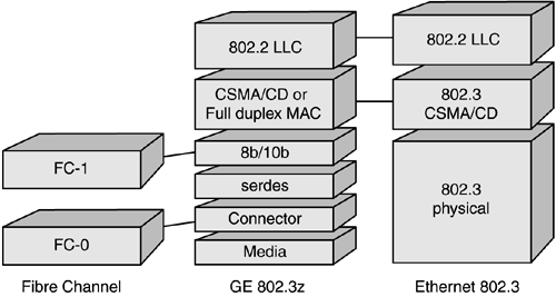
In contrast to the Fibre Channel stack, Gigabit Ethernet's 8b/10b encoding occurs at the physical layer via sublayers in the media-dependent physical group. As shown in Figure 6-1, Fibre Channel layers FC-0 and FC-1 are brought into the lower-layer physical interface, whereas traditional 802.3 Ethernet provides media access control (MAC) and logical link control (LLC), or its offspring, MAC Client, to support the upper-layer protocols. Figure 6-1. Gigabit Ethernet uses Fibre Channel lower layers for signaling
Gigabit Ethernet uses standard Ethernet framing, as shown in Figure 6-2. The preamble and start-of-frame (SFD) delimiter are followed by the destination (DA) and source (SA) 48-bit MAC addresses of the communicating devices. Creative use of bytes within the length/type field enables enhanced functionality such as VLAN tagging, as discussed shortly. The data field can contain as many as 1,500 bytes of user data, with pad bytes if required. The CRC is part of the frame check sequence (FCS). An optional frame padding is provided by the extension field, although this is required only for gigabit half duplex transmissions. Figure 6-2. Standard Ethernet frame format
Ethernet frame addressing gets data from one device to another on the same network segment. When the data is intended for a recipient outside the local LAN segment, network-layer addressing is required. The Ethernet frame therefore serves as the outer envelope for the network packet. It may contain, in addition to network addressing (such as IP), a session control protocol (such as TCP). IP protocol over Ethernet is inserted into the data field and provides the network-layer routing information to move user data from one network segment to another. TCP provides higher-level session control for traffic pacing and the ability to recover from packet loss. Although IP can be carried in other frame formats, link-layer enhancements for Ethernet offer additional reliability and performance capability unmatched by other transports. These include link aggregation, link-layer flow control, virtual LANs, and quality of service. IEEE 802.3ad Link AggregationLink aggregation, or trunking, provides high bandwidth for switched networks by provisioning multiple connections between switches or between a switch and an end device such as a server. Link aggregation also facilitates scaling the network over time, because it lets you add links to a trunked group incrementally as bandwidth requirements increase. As shown in Figure 6-3, two Gigabit Ethernet switches can share three aggregated links, for a total available bandwidth of 7.5Gbps full duplex. Figure 6-3. Link aggregation between two Gigabit Ethernet switches
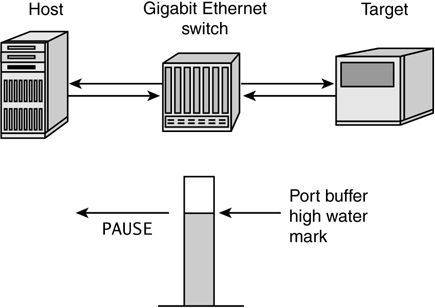
Link aggregation must resolve several issues to avoid creating more problems than it solves. In typical bridge environments, the spanning tree algorithm would, upon encountering multiple links between two devices, simply disable the redundant links and allow only a single data path. This would prevent duplication of frames and potential out-of-order delivery. Link aggregation must therefore make multiple links between two devices appear as a single path while simultaneously providing a mechanism to avoid frame duplication and ensure in-order frame delivery. You could implement this by manipulating MAC addresses (for example, assigning the same MAC address to every trunked link) or by inserting link aggregation intelligence between the MAC client and MAC layers. You would have to monitor the status of link availability, current load, and conversations through the trunk to ensure that frames are not lost or inadvertently reordered. In-order delivery of frames is guaranteed if a conversation between two end devices is maintained across a single link in the trunk. Although link aggregation is not as efficient as simply shipping each frame over any available connection, it avoids the extra logic required for frame ordering and reassembly before delivery to the recipient. At the same time, additional transactions by other devices benefit from the availability of the aggregated interswitch links, and switch-to-switch bottlenecks are avoided. Link aggregation as specified in IEEE 802.3ad is almost mandatory for IP-based storage networks, particularly when multiple Gigabit Ethernet switches are used to build the SAN backbone. Along with 802.1p/Q prioritization, link aggregation can ensure that mission-critical storage traffic has an available path through the network and that multiple instances of mission-critical transactions can occur simultaneously. This requirement will be satisfied temporarily by the arrival of 10Gbps uplinks between switches, but these will inevitably be trunked to provide even higher bandwidth over time. IEEE 802.3x Flow ControlFlow control at the data-link level helps to minimize frame loss and avoids latency due to error recovery at the higher-layer protocols. In Fibre Channel, flow control for Class 3 service is provided by a buffer credit scheme. As buffers are available to receive more frames, the target device issues receiver readys (R_RDYs) to the initiator, one per available buffer. In Gigabit Ethernet, link-layer flow control is provided by the IEEE 802.3x standard. As illustrated in Figure 6-4, the 802.3x implementation uses a MAC control PAUSE frame to hold off the sending party if congestion is detected. If, for example, receive buffers on a switch port are approaching saturation, the switch can issue a PAUSE frame to the transmitting device so that the receive buffers have time to empty. Typically, the PAUSE frame is issued when a certain high water mark is reached, but before the switch buffers are completely full. To use IEEE 802.3x flow control efficiently, all switches in the data path must support bidirectional flow control. Figure 6-4. Sending PAUSE frames to pace incoming traffic
Because the PAUSE frame is a type of MAC control frame, the frame structure is slightly different from the conventional data frame. The length/type field is used to indicate the presence of a MAC control frame. The flow control mechanism within the control frame is a hold-off pause_time value, establishing how long the sending party should pause before continuing to send frames. The pause_time cannot be specified in fixed units such as microseconds, because this would prove too inflexible for backward compatibility and future Ethernet transmission rates. Instead, the pause_time is specified in pause_quanta, with 1 pause_quanta equal to 512 bit_times for the link speed being used. The timer value can be between 0 and 65,535 pause_quanta, or a maximum of ~33 milliseconds at Gigabit Ethernet's 1.25Gbps transmission rate. If the device that issued the PAUSE frame empties its buffers before the stated pause_time has elapsed, it can issue another PAUSE frame with the pause_time set to zero. This signals the transmitting device that frame transmission can resume. Because PAUSE frames can be used between any devices and the switch ports to which they are attached and because Gigabit Ethernet allows only one device per port, there is no need to personalize the PAUSE frame with the recipient's MAC address. Instead, a universal, well-known address of 04-80-C2-00-00-01 is used in the destination address field. When a switch port receives the PAUSE frame with this address, it processes the frame but does not forward it to the network. The 802.3x flow control provided by Gigabit Ethernet switches creates new opportunities for high-performance storage traffic over IP. Fibre Channel Class 3 service has already demonstrated the viability of a connectionless, unacknowledged class of service, provided that there is a flow control mechanism to pace frame transmission. In Fibre Channel fabrics using Class 3, as with 802.3x in Ethernet, the flow control conversation occurs between the switch port and its attached device. As the switch port buffers fill, it stops sending R_RDYs until additional buffers are freed. In Gigabit Ethernet, this function is performed with PAUSE frames, with the same practical result. In either case, buffer overruns and the consequent loss of frames is avoided, and this is accomplished with minimal impact to performance. IEEE 802.1Q VLAN TaggingVirtual LANs in a switched Ethernet infrastructure let you share network resources such as large Gigabit Ethernet switches while segregating traffic from designated groups of devices. As with Fibre Channel zoning, members of a virtual LAN can communicate among themselves but lack visibility to the rest of the network. VLAN tagging was standardized in 1998 through the IEEE 802.1Q committee. You create virtual LANs by manipulating the length/type field in the Ethernet frame. To indicate that the frame is tagged, a unique 2-byte descriptor of hex 81-00 is inserted into the field. This tag type field is followed by a 2-byte tag control information field, as shown in Figure 6-5. This field carries the VLAN identifier and user priority bits, as described shortly. The 12-bit VLAN identifier allows you to assign as many as 4,096 VLANs on a single switched infrastructure. Figure 6-5. IEEE 802.1Q VLAN tag fields
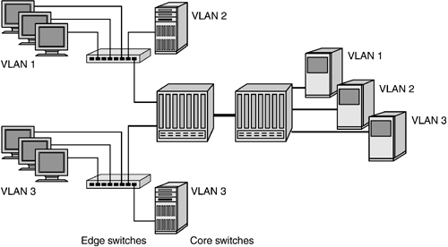
From a performance standpoint, VLAN tagging is a highly efficient means to segregate network participants into communicating groups without incurring the overhead of MAC address filtering. Intervening switches use the logical VLAN identifier, rather than a MAC address, to properly route traffic from switch to switch, and this in turn simplifies the switch decision process. As long as the appropriate switch port is associated with the proper VLAN identifier, no examination of the MAC address is required. Final filtering against the MAC address occurs at the end point. All major vendors of Gigabit Ethernet switches support the 802.1Q standard. This makes it a useful feature not only for data paths that must cross switch boundaries but also for heterogeneous switched networks. For IP storage network applications, 802.1Q facilitates separation of storage traffic from user messaging traffic, as shown in Figure 6-6. Figure 6-6. VLANs on a common switch infrastructure. VLAN 2 is a storage network
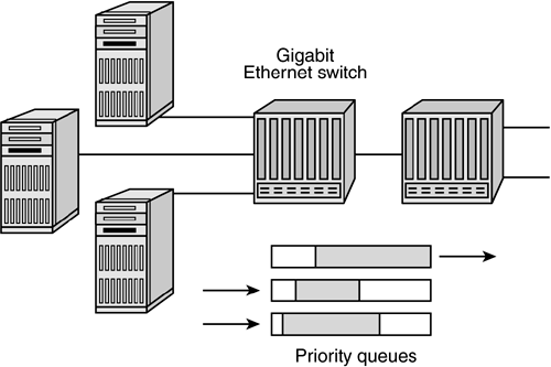
IEEE 802.1p/Q Frame PrioritizationThe 802.1Q VLAN tag control information field allocates 3 bits for user priority. The definition for these user priority bits is provided by IEEE 802.1p/Q and enables individual frames to be marked for priority delivery. The quality of service (QoS) supported by 802.1p/Q allows for eight levels of priority assignment. As shown in Figure 6-7, this ensures that mission-critical traffic will receive preferential treatment in potentially congested conditions across multiswitch networks and thus minimizes frame loss due to transient bottlenecks. Figure 6-7. Frames with highest priority are processed first
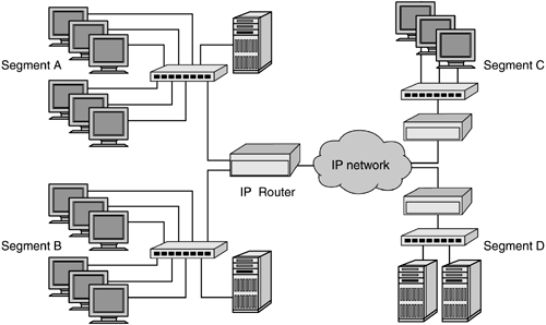
For storage network applications, the ability to prioritize transactions in an IP-based SAN is a tremendous asset. Storage networks normally support a wide variety of applications, not all of which require high priority. Updating an online customer order or a financial transaction between banks, for example, rates a much higher priority for business operations than does a tape backup stream. The class of service provided by 802.1p/Q allows storage administrators to select the applications that should receive higher-priority transport and assign them to one of the eight available priority levels. In a multiswitch network, class of service ensures that prioritized frames have preference across interswitch links. 6.1.2 TCP/IPLayer 3 IP network routing solves a fundamental problem of layer 2 networks. Layer 2 networks have a single address space based on MAC or a similar link layer address. Network-wide queries such as broadcasts are distributed throughout the network address space, creating a potential for broadcast storms that would bring normal network traffic to a halt. Broadcast storms were a notorious problem in the 1980s for bridged Ethernet or Token Ring networks. What was needed was a means to isolate link-level broadcasts to a single network segment and therefore eliminate network-wide disruptions. That solution was provided by IP routers, which established Cisco's dominance of the data communications market. IP adds an address layer above the link-level MAC address. Traffic within a network segment can use link layer addressing to send frames from one device to another. Traffic destined for devices beyond the local segment are sent to an IP router or gateway, which uses the upper-layer IP address to determine where frames must be sent. Link layer broadcasts are restricted to the local segment, thus preventing network-wide broadcast storms. In Figure 6-8, four network segments are joined by IP routers. Communications between devices within segment A, for example, would use Ethernet MAC addressing to send and receive frames. A link-level failure or broadcast storm in segment A would be blocked by the IP router and not passed to the rest of the network. Segment B, in this instance, could continue to communicate with devices in segment D using IP addressing because the rest of the network would be operational. Figure 6-8. A network segmented by IP routers
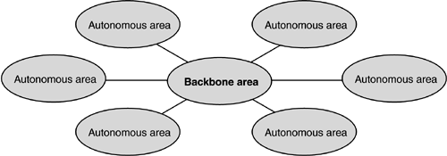
Collectively, all networks connected by IP routers can be referred to as an IP network. The Internet, for example, is composed of hundreds of thousands of individual networks, each with its own unique IP address space. IP AddressingUnlike proprietary networking protocols, IP has evolved in the public realm. The IP addressing scheme therefore assumes that individual end devices not only have a unique identity within a particular network but also are unique globally. The traditional IP address scheme (IPv4) uses a 32-bit address that is divided into network identifiers and host (device) identifiers. For convenience, the 32 bits are expressed in a dotted decimal notation for example, 192.168.20.10. The original IPv4 addressing relied on various classes of addresses to provide address ranges for large and small networks. To distinguish between the network and host portions of an IP address, a subnet mask is used. The subnet mask sets 1 bits to indicate the network portion, and 0 bits to indicate the host portion. This arrangement makes it possible to subdivide a class of IP addresses into small portions that can be easily administered. Although IPv4's 32-bit address space allows for more than 4,000,000,000 (four billion) unique addresses, the class-based allocation of blocks of addresses has proved to be too restrictive to satisfy the ever-increasing demand for IP connectivity. Consequently, a new IPv6 enhancement allocates 128 bits for an IP address, for a 4,000,000,0003 (four billion cubed) advantage over the IPv4 total address space. In addition, the class-based scheme for IPv4 has been replaced by a more flexible classless IP address scheme. Classless Inter-Domain Routing (CIDR) was created in the mid-1990s as a transitional solution to IPv4 address allocation until IPv6 could be developed. CIDR essentially overturns the notion of fixed IP classes and offers a more flexible means to demarcate networks and hosts. CIDR ignores the upper bits that identify IP classes and simply indicates the number of bits that should be used for calculating the network portion of the address. The CIDR postfix /15 appended to a network address of 172.16.0.0/15 would indicate that the first 15 bits of the address should be used to identify the network portion. Because a /15 mask is shorter than the 16 bits normally associated with the Class B 172.16.0.0 address, CIDR may not be compatible with earlier network interface card (NIC) device drivers. It is especially beneficial, however, for ISPs to use in allocating addresses that scale to their customers' requirements. For all the difficulties associated with IPv4 address allocation, IP addressing offers a viable long-term solution for future storage networks. The deployment of a virtually unlimited IPv6 address space will accompany the widespread adoption of readily available storage as storage network solutions expand from the data center to consumer-oriented applications. This universality would be difficult to achieve with the more finite address space and single fabric topology provided by Fibre Channel. In addition, IPv6 standards include QoS and security features that are useful for a wide variety of networked storage solutions. Address Resolution ProtocolWhen an IP packet is sent between networks, the header contains the source and destination IP addresses but no information on the destination's lower-level MAC address. A workstation may have both a 48-bit MAC address and a 32-bit IP network address, and it cannot receive frames based on the IP address alone. An IP router must therefore be able to associate a specific IP address with the appropriate MAC address in order to complete delivery. This process, called address resolution, requires a special protocol (ARP) consisting of request and reply packets. ARP relies on broadcasts that could be potentially disruptive to the LAN. Having received a data packet addressed to the local IP subnet, for example, an IP router broadcasts an ARP request throughout the local LAN segment. The ARP request contains the MAC and IP address of the router (the source) and the IP address of the intended recipient (the destination). Every host on the LAN segment examines the broadcast request and compares the IP address it contains to its own. If there is a match, the host issues an ARP reply to the router's MAC address and inserts its own MAC address as the source of the reply. The router can then resolve the MAC-to-IP addressing and send the original data packet on the destination LAN segment using the host's proper MAC address. IP RoutingIP routing relies on layer 3 network addressing for transporting packets between routers and relies on layer 2 addressing for delivering packets to their final destination on local LAN segments. When an IP router receives a packet from a local Ethernet segment, for example, it strips off the Ethernet header (layer 2) and uses the IP header (layer 3) to make a forwarding decision. At the receiving end, a layer 2 header must be reapplied before the packet can be sent to the appropriate destination IP address. This process allows communication using IP between heterogeneous LAN topologies for example, between Ethernet-based and Token Ring-based hosts. The IP routers themselves must have a means to exchange information about which IP networks or subnets they are attached to. Several routing information methods have evolved, including the original Routing Information Protocol (RIP) and Open Shortest Path First (OSPF). RIP-2, which allows for variable-length subnet masks, is a distance-vector protocol. As routers exchange information about their attached IP networks, RIP calculates optimum paths through the network based on the shortest number of hops between source and destination. Each IP router represents a single hop. In a meshed network, there may be multiple paths between a source and destination network. Calculating IP routes based on the fewest number of hops would therefore appear to be the best means to get data from A to B. In reality, the hop count method does not account for the state of the links in the network. IP routers may have different types of links between them; for example, one hop may be connected by a Fast Ethernet link (100Mbps) whereas another may be connected by a T3 communications link (45Mbps). In addition, some links may bear more traffic than others, so even though there may be fewer hops along a single path vis-à-vis another, packets forwarded along that path may face congestion and may be discarded. The limitations of distance-vector routing encouraged the development of other protocols, including OSPF. Open Shortest Path First is a link-state protocol. Instead of simply calculating optimum paths based on number of hops, OSPF monitors the state of the links to which an IP router is attached and calculates the relative cost of moving data from one point to another based on bandwidth, current traffic load, and other link-dependent conditions. Link-state information is transmitted to neighboring IP routers so that the most efficient data paths can be selected. OSPF also introduces the concept of autonomous areas within the IP-routed network. As shown in Figure 6-9, the OSPF area hierarchy includes autonomous areas of IP routers that are ultimately linked through a common backbone area (area 0). This hierarchical scheme restricts OSPF broadcasts to specific areas and so prevents flooding of the entire network with routing information updates whenever changes occur. Figure 6-9. OSPF backbone and autonomous areas
Another advantage of OSPF is the ability it gives you to quickly accommodate changes in the network. In network terminology, convergence refers to the reestablishment of network connections after a major change has occurred. RIP uses an update interval method that can result in prolonged link failures before new paths are broadcast. In addition, because there are no autonomous areas as in OSPF, convergence time depends on the propagation of routing information throughout the network before stability is achieved. OSPF shortens convergence time by issuing state changes as soon as link failures are detected and by restricting (via areas) the number of IP routers that must be notified of changes. Fibre Channel routing uses a subset of the OSPF protocol. FSPF calculates the shortest path on the basis of link speed, although new proposals would also include latency over distance as a metric. TCP Session ControlThe Transmission Control Protocol (TCP) is a connection-oriented transport protocol sitting above the IP network layer. Instead of simply pushing data from source to destination on a best-effort basis, TCP first establishes a transmission connection between the communicating pair and imposes a system of datagram acknowledgments to ensure that each transmission arrived intact. TCP also provides a mechanism to recover from packet loss due to errors or network congestion. Because TCP is optimized for potentially congested networks, it is the protocol of choice for wide area communications and is used extensively in enterprise networks and the Internet. The cost for leveraging TCP/IP's data integrity features, however, is measured in performance. Someone must do the work. In the case of a TCP/IP driver on a host computer system, the CPU must process the TCP routines as datagrams are transmitted and received, resulting in 50 percent to 80 percent CPU utilization for intensive, high-speed TCP/IP transactions. In addition, the extra transmissions required for session establishment, acknowledgments, and session teardown place more traffic on the network infrastructure. But without the transport layer delivery guarantees provided by TCP/IP, the potential burden on the network and host CPUs might be even greater, particularly if upper-layer applications were forced into constant error recovery and retransmission of larger units of data. TCP introduces procedures for establishing communications between two network entities, segmentation of messages for hand-off to the IP layer, sequence numbers and acknowledgments to track the transmission of bytes across the link, a ramping and back-off algorithm to pace the traffic flow, and recovery routines to handle packet loss through the network. Like UDP, TCP uses port numbers to facilitate communications between upper-layer applications. The TCP port number and IP address can be combined to create unique identifiers for abstractions known as sockets. A socket represents the end point of a TCP session. Because TCP is a connection-oriented protocol it requires acknowledgment for each TCP segment transmitted. If TCP waited for an acknowledgment before sending the next segment in queue, however, performance would be adversely affected. To optimize flow control while maintaining acknowledged service, TCP uses a sliding window, which allows multiple segments to be sent before acknowledgments are received. The window size is negotiated during connection setup and typically reflects the buffering capability of the communicating devices. The larger the receive buffers, the greater the number of segments that can be transmitted en masse before acknowledgments are issued. Although TCP requires an initial setup between two devices, the logical connection that is established does not specify the bandwidth available for data transport. The underlying network could be a relatively slow WAN link, an oversubscribed network, or a wide open switched gigabit infrastructure. Because the network may be unreliable, TCP makes no assumptions about how quickly it can transmit its data. Instead, it probes the network capacity by gradually increasing the number of packets sent until congestion is detected or the sliding window value is reached. This ramping algorithm allows TCP to throttle transmissions and so adjust for variable network conditions. The TCP slow start algorithm tests the rate at which TCP can inject segments into the network by observing the latency of acknowledgments that are returned by the destination device. The more quickly acknowledgments are received, the more quickly additional segments can be issued. With slow start, a congestion window value (cwnd) is initialized to a value of one segment. As each ACK is received from the destination, the congestion window is incremented exponentially. After the first ACK is received, the congestion window is increased to two segments. When those are acknowledged, the window increases to four segments, and so on. The sliding window algorithm depends on the buffering capacity of the destination device that is, how quickly it can process its receive buffers and return acknowledgments. The slow start algorithm also relies on responses from the destination, but it allows the source to limit segment transmissions until confidence in the underlying network is established. For streaming storage applications such as backup, slow start has no significant impact on performance. For storage applications that may require exchanges of smaller frames, such as on-line transaction processing, slow start may affect throughput, especially over long distances. In the event of errors or dropped packets due to network congestion, TCP's constant monitoring of the session enables it to recover packets from the point of failure. This ensures that although individual packets may be dropped, they will be retransmitted and the data recovered. On a well-designed network, TCP recovery is rarely invoked. Nonetheless, the TCP layer at both ends of the transaction must continue monitoring sequence numbers and acknowledgments. TCP processing can consume significant host CPU cycles, as evidenced by the sluggish behavior of any PC when downloading large files from the Internet. New technologies for offloading TCP processing from the host are now available on some Gigabit Ethernet adapter cards. TOE (TCP offload engine) chip sets remove the burden of TCP overhead from the host CPU and thus free the CPU for user processing. Chapter 7 examines the use of TOE technology for accelerating storage over IP. TCP is a form of insurance against unforeseen network disruptions. Session control, sliding windows, slow start, packet recovery, and in-order delivery ensure that despite network difficulties, data will still arrive intact. Although this technology satisfies one of the requirements of mission-critical storage applications, it does not mean that storage data should be consigned arbitrarily to any TCP/IP network. To avoid timeouts at the upper SCSI layer and degraded performance for storage applications, the SAN architect must also ensure that the network infrastructure is properly designed for the intended load. Oversubscription of links may be permissible for some applications and anathema to others. Like any insurance, TCP recovery provides security against loss, but you may also suffer penalties if it is invoked too often. |
EAN: 2147483647
Pages: 171
