4.4 Building Extended Fabrics
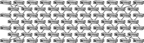
| As SANs proliferate in enterprise networks, fabrics composed of multiple switches have become more commonplace. Showcase applications such as full-motion video editing and high-performance relational database servers are driving large fabric configurations. Extended fabrics built for disaster recovery applications employ multiple switches separated by long fiber-optic runs, DWDM (dense wave division multiplexing), or IP tunneling. The scalability promised by Fibre Channel is being challenged at every step of the technology's adoption, forcing standards to prove themselves in workable products. Building large multiswitch fabrics has been difficult for both technical and vendor-driven reasons. The theoretical use of 239 switches in a single fabric cannot be achieved with today's fabric switch products. Even in a single-vendor solution, achieving stable fabrics of more than a dozen switches is problematic. One reason is the amount of switch-to-switch communications that must occur before the fabric can become active. Even in a fairly small multiswitch fabric, the distribution of address blocks to each switch and the exchange of routing tables and SNS information may require more than 10 minutes before a fabric achieves stability. Latency across multiple switches is also an issue, and switch vendors have recommended hop count limitations of three to seven switches to avoid timing issues. These practical issues are not dependent on Fibre Channel standards but instead are driven by the current state of the art of the products. E_Port connections (also known as interswitch links, or ISLs) have yet to achieve the level of interoperability commonplace for Ethernet switch products. In the category of vendor-driven issues, multivendor switch interoperability has been the most contentious. For one switch to communicate with another, a switch-to-switch protocol is required. In the early stages of fabric switch development, each vendor implemented its own switch-to-switch protocol, making it impossible for customers to deploy multivendor fabrics. This approach was contrary to the open systems expectations of customers, and marketing pressure eventually pushed fabric switch vendors to cooperate in resolving interoperability problems. The Fabric Shortest Path First protocol, for example, was finally developed as a common standard when one switch vendor reverse-engineered the switch-to-switch protocol of another and took it into the NCITS/ANSI T11 standardization process. Even now, however, subtle differences in switch-to-switch protocol implementation require vendors to implement multiple compatibility modes that must be configured manually before switches can be connected. Another obstacle to large fabrics has been the influence of marketing on the engineering recommendations given to customers. The diagram in Figure 4-15, for example, is an actual vendor recommendation for building a large fabric composed of 16-port fabric switches. The vendor in question did not simply recommend a more rational configuration based on 128-port switches, because at the time it did not have large port count switches in its product portfolio. Consequently, the proposed configuration introduced innumerable points of failure, resulted in a significant management burden, required that user ports be sacrificed to achieve interswitch links, and violated the vendor's own recommendation for hop count limitation. In practice, this proposed configuration would never have worked. That fact, however, did not prevent vendor marketing from positioning this sort of configuration as a viable SAN solution. Figure 4-15. A fabric configuration that reflects the undue influence of marketing on systems engineering
Although little can be done about overly aggressive and misleading vendor marketing, the technical issues that large fabrics must address are not insurmountable. Standardization of E_Port connectivity has seen encouraging progress over the past several years, and the continued introduction of large port count Fibre Channel directors offers streamlined solutions for large fabric deployments. 4.4.1 E_Port StandardizationE_Port connectivity involves several Fibre Channel standards that define various processes that are performed between linked fabric switches. The standard most relevant to E_Port connectivity is NCITS/ANSI FC-SW-2, which defines the requirements for the FSPF protocol. FSPF is a subset of the more commonly used Open Shortest Path First (OSPF) standard used in IP routing. Like OSPF, FSPF is a link state routing protocol. Link state routing protocols were developed as an enhancement to distance vector routing protocols such as RIP (Routing Information Protocol), which simply determine the optimum path based on the number of hops from source to destination. In a link state routing protocol, the best route through a network is determined by the optimum number of links (least cost) offered between switches. In the case of FSPF, the relative cost of traversing multiple switches is driven by the link speed provided by E_Port connections. For OSPF, additional variables such as current utilization, or load, may be factored in to the cost equation. Optimum routes through FSPF Fibre Channel fabrics are based on a single metric expressed in the following formula: FSPF Cost = S(1,000) x1.0625 [Gbps] / Line Rate [Gbps]. Consequently, the cost of a standard 1Gbps E_Port connection between two switches is 1,000. As shown in Figure 4-16, the more E_Port links a connection must traverse, the higher the cost. Because the path from switch A to switch D has least cost when routed via switch B, the more costly path through C will not be selected unless the E_Port link between switch B and switch D fails. The cost calculation becomes more interesting (and less like simple RIP) when mixed 1Gbps and 2Gbps E_Port connections are deployed. Figure 4-16. FSPF link cost calculation based on 1Gbps interswitch links
A proposal for a version 2 of FSPF (FSPFv2) introduces the variable of latency into the link cost equation. This initiative has been prompted by initial experience with native Fibre Channel SAN extension over longer distances in which speed-of-light latency impacts performance. By factoring in latency, it is possible to select a more optimal route that provides lower bandwidth but less latency compared with a higher-speed link with more latency. In addition to routing information, it is desirable to exchange zoning information over E_Port connections. The ability to merge zoning tables between Fibre Channel switches allows administrators to allocate storage resources to the appropriate hosts even as SANs scale to larger multiswitch configurations. How zoning is implemented in individual switches may be proprietary, but establishing a standards-based way to share zone information between various switch products facilitates deployment of more complex SANs. The exchange of FSPF routing and zoning parameters over E_Port connections helps to build the framework of the fabric. The fabric itself, however, is only a convenience for communication among servers, disks, and tape devices. Another essential ingredient for E_Port connectivity is therefore exchange of Simple Name Server data so that servers can discover and establish connections with storage resources throughout the fabric. The name server standard is covered by NCITS/ANSI FC-GS-2 and for multiswitch configurations relies on compliance with FC-SW-2 for successful exchange of SNS information. 4.4.2 Principal Switch SelectionTo avoid duplication of addressing between multiple Fibre Channel switches, Fibre Channel E_Port connectivity requires a process for assigning blocks of unique addresses to individual switches. In the principal switch selection process, one fabric switch assumes the role of principal switch and automatically allocates blocks of 64K addresses to the other switches in the fabric. This gives each switch a unique Domain_ID and avoids address duplication in the fabric. In a single-switch SAN, an individual switch would serve as its own principal switch. The principal switch facility was developed to automate link layer addressing in Fibre Channel fabrics. In practice, most vendor implementations allow (or require) that an administrator manually determine which switch will serve as principal and which as secondary. Principal switch selection is predicated on an orderly attachment to the fabric. If multiple E_Port connected switches are powered up or enabled simultaneously, they will attempt to contact their peers by issuing frames to a well-known address of x'FF FF FD', which represents the fabric controller of each switch. This frame flooding continues until a preset timeout value (F_S_TOV, or fabric stability timeout value) is reached. In the end, the switch with the highest principal switch priority is determined, and address blocks are assigned. If an active fabric is already operational, a newly introduced switch will either gracefully enter the fabric (if the switch is freshly enabled) or trigger a new principal switch selection process (if the switch is already active and assumes that it is still the principal switch). The build fabric link service is nondisruptive and enables a newly introduced switch to gain a unique Domain_ID and participate in the enlarged fabric. The reconfigure fabric link service is disruptive in that Domain_IDs may change, forcing the devices attached to a switch to log on to the switch again and acquire new addresses. Any storage traffic on the fabric will be discarded, and if the reconvergence is lengthy, higher-level SCSI timeouts may occur. In either of these cases, the fabric will eventually stabilize and additional switch-to-switch services, such as SNS exchange and zone merging, can occur. The potential for disruptive reconfiguration of the fabric thereafter may occur if another operational switch is inserted into the fabric or if the principal switch disappears due to a broken E_Port connection. The likelihood of the latter is exacerbated when E_Port connections are stretched over distance. A break in the wide area link or transient loss of connectivity in an IP tunneled solution may cause the previously joined fabric switches at each side to split into separate SAN islands. Administrators who have attempted to create extended or large fabrics are intimately familiar with fabric reconvergence issues. The very mechanism that is meant to simplify Fibre Channel fabric deployments may result in disruptions if the fabric is not properly managed. New switches must be either disabled or powered off before they are inserted into an operational fabric, and switch-to-switch links over wide area connections must be monitored for stability. |
EAN: 2147483647
Pages: 171