Per-VLAN Spanning Tree Plus
As discussed in Chapter 5, 802.1Q has defined standards-based technologies for handling VLANs. To reduce the complexity of this standard, the 802.1 committee specified only a single instance of Spanning Tree for all VLANs. Not only does this provide a considerably less flexible approach than the Per-VLAN Spanning Tree (PVST) adopted by Cisco, it creates an interoperability problem. To address both of these issues, Cisco introduced the Per-VLAN Spanning Tree Plus (PVST+) protocol in 4.1 code on the Catalyst 5000s (all 4000s and 6000s support PVST+). This feature allows the two schemes to interoperate in a seamless and transparent manner in almost all topologies and configurations.
There are both advantages and disadvantages to using a single Spanning Tree. On the upside, it allows switches to be simpler in design and place a lighter load on the CPU. On the downside, a single Spanning Tree precludes load balancing and can lead to incomplete connectivity in certain VLANs (the single STP VLAN might select a link that is not included in other VLANs). Given these tradeoffs, most network designers have concluded that the downsides of having one Spanning Tree outweigh the benefits.
Note
Although the initial release of 802.1Q only specified a single instance of the Spanning-Tree Protocol, the IEEE is working on multiple instances of STP in the 802.1s working group.
PVST+ Network Region Types
PVST+ allows for three types of regions in the network:
A group of traditional (pre-4.1) Catalysts form a PVST region with each VLAN using a separate instance of the Spanning-Tree Protocol.
Pure 802.1Q switches use a single instance of the Spanning-Tree Protocol, the Mono Spanning Tree (MST). A group of these switches forms an MST region.
Catalysts running 4.1 and later code form a PVST+ region.
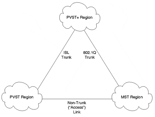
Given that pure 802.1Q switches only support 802.1Q-style trunks and PVST switches only support ISL trunks, these regions can only be connected in a limited set of combinations:
PVST and PVST+ regions can connect over ISL trunk links.
MST and PVST+ regions can connect over an 802.1Q trunk.
Notice that an MST and PVST region cannot be connected via a trunk link. Although it is possible to provide a non-trunk connection between the two regions by using an access (non-trunk) link, this is of limited usefulness in real-world networks. Figure 7-26 illustrates the three types of STP regions and potential linkages.
Figure 7-26. Three Types of Regions Supported under PVST+

Because it provides interoperability between the other two types of regions, a PVST+ region is generally used in the backbone. It connects to MST regions via 802.1Q trunks and PVST regions via ISL links. However, more flexible configurations are allowed. For example, two PVST+ regions can connect via an MST backbone region.
PVST+ Mapping and Tunneling
PVST+ utilizes two techniques to provide transparent STP support across the three types of regions:
Mapping
Tunneling
Mapping is used between PVST and PVST+ regions. Each Spanning Tree in a PVST region maps to a separate Spanning Tree in PVST+ on a one-to-one basis. The same occurs in the reverse direction. This process is both simple and obvious.
On the other hand, when converting between MST and PVST+ regions, both mapping and tunneling must be used. The single Spanning Tree used in the MST region maps to a single Spanning Tree in the PVST+ region. This Spanning Tree is referred to as the Common Spanning Tree (CST) and uses VLAN 1. When going in the opposite direction, all Spanning Trees other than the CST belonging to VLAN 1 use tunneling. The BPDUs for these VLANs are flooded throughout the MST region and reach other PVST+ bridges on the far side.
How does Cisco implement the tunneling approach that allows these PVST+ BPDUs to be flooded? In the case of mapped VLANs, the BPDUs are sent to the well-known STP MAC address of 01-80-C2-00-00-00. All bridges conforming to the 802.1D specification do not flood these frames. Rather, the frames are forwarded to the CPU for STP processing. If necessary, the STP process generates new BPDUs to pass on to other devices. If the PVST+ BPDUs were sent into the MST region using this MAC address, they would only travel as far as the first bridge or switch. Because MST devices do not understand multiple instances of the Spanning-Tree Protocol, these BPDUs would be dropped. However, because PVST+ uses a different multicast MAC address, the MST devices would flood the BPDUs as if they were normal data. As these BPDUs reach other PVST+ switches on the far side of the MST region, they can be processed as if they were sent to the well-known MAC address.
To accomplish this flooding process, Cisco has utilized the destination MAC address 01-00-0C-CC-CC-CD. Notice that this address differs from the usual Cisco multicast address used by CDP, VTP, DISL, PAgP, and DTP: 01-00-0C-CC-CC-CC. Although these only differ by one bit, the difference is critical. Just as all 802.1D bridges absorb frames sent to 01-80-C2-00-00-00 for processing (in other words, they are regenerated, not flooded), all Cisco devices absorb 01-00-0C-CC-CC-CC for processing. If the usual Cisco Multicast were used, all existing Catalyst devices would not flood the PVST+ BPDUs, breaking the tunneling process. However, by using a new multicast address, older Cisco bridging devices flood the BPDUs as normal data. As mentioned in the previous paragraph, also notice that the CST BPDUs must be sent to the well-known MAC of 01-80-C2-00-00-00 (this is the MAC addresses specified for STP in the 802.1D specification) so that they can be processed normally by the devices in the MST region.
PVST+ and Spanning Tree Load Balancing
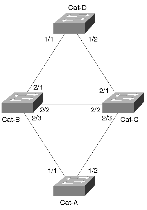
An interesting question arises when using PVST+: How do you implement STP load balancing? Fortunately, most of the techniques discussed earlier work the same under PVST+ as they were explained under the PVST rules used earlier. The most significant difference has to do with the mechanics of the tunneling process. Specifically, when MST switches flood the PVST+ BPDUs, they are only flooded out ports that are in the Forwarding state. Not only can this delay the initial propagation of PVST+ BPDU through the MST region, it can affect STP load balancing. For example, consider Figure 7-27, the simplified campus backbone used throughout this chapter.
Figure 7-27. PVST+ Load Balancing

Five basic combinations of MST, PVST, and PVST+ switches can be used in this network:
All switches are PVST devices This is the case discussed in the "Spanning Tree Load Balancing" section earlier. All of the load balancing techniques covered in that section obviously work here.
All switches are PVST+ devices Load balancing can be implemented using exactly the same techniques as with PVST switches. The PVST+ and CST BPDUs are handled without any user configuration.
All switches are MST devices No STP load balancing is possible under the current version of 802.1Q.
An IDF switch is an MST device and remaining devices are PVST+ devices For PVST+ BPDUs and traffic to pass through both uplink ports on the IDF switch, both ports need to be in the STP Forwarding state. Beyond that, normal STP load balancing techniques can be utilized.
An MDF switch is an MST device and remaining devices are PVST+ devices For PVST+ BPDUs and traffic to pass through all ports of the MDF switch, all of the ports must be placed in the Forwarding state. After that has been accomplished, normal STP load balancing can be done.
In short, PVST+ allows all of the usual Spanning Tree load balancing techniques to be used with one exception all inter-switch ports on MST devices should be in the Forwarding state.
Note
Load balancing might be possible if some MST ports are Blocking. However, the load balancing design requires careful analysis. In general, it is easiest to design the network to have all inter-switch MST ports in the Forwarding state (if possible).
Two problems arise when the MST ports are not forwarding:
PVST+ BPDUs are only flooded out a subset of the ports, and therefore only learn a subset of the topology.
Blocking MST ports destroy the capability to implement load balancing. Recall that when an MST switch puts a port in the Blocking state, it blocks that port for allVLANs. Because this forces all traffic to use a single path, load balancing is no longer possible.
Tip
The mapping and tunneling aspects of PVST+ require no user configuration or intervention. This allows plug-and-play interoperability. However, load balancing might require some extra STP tuning to force the MST ports into the Forwarding state.
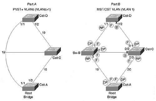
It can be tricky to meet the requirement that all ports on the MST switches forward while also distributing the traffic across multiple paths. A couple of examples illustrate this point. First, consider the case of an MDF MST switch as shown in Figure 7-28. Cat-B has been replaced by Sw-B, a generic 802.1Q MST switch.
Figure 7-28. MDF MST Switch Load Balancing

Part A in Figure 7-28 illustrates the tunneling process of PVST+ BPDUs through an MST switch (this is used for VLANs other than VLAN 1). Because the MST switch floods the PVST+ BPDUs out all inter-switch ports (assuming that the requirement of all ports Forwarding is met), it is as though the MST switch does not exist. An interesting consequence of this is that the left path appears to only have a cost of 19, whereas the right path has the usual cost of 38 (19+19). In other words, Cat-A, the Root Bridge, originates Configuration BPDUs with a cost of zero. These BPDUs arrive without any modification on Cat-D:Port-1/1 where the cost is increased to 19. On the right link, Cat-C receives the BPDUs and increases the Root Path Cost to 19. When Cat-D:Port-1/2 receives these, it increases the Root Path Cost to 38. This issue is easily overcome by increasing cost to some large value such as 1000 on the link you do not want the traffic to take (this is another example of a case where using the default portvlancost behavior of lowering the cost by one does not work as discussed in the earlier section "Decreasing Path Cost for Load Balancing"). For example, traffic for VLAN 3 could be forced to take the right link by increasing VLAN 3's Path Cost on Cat-D:Port-1/1 to 1000 (the cost of the right path would remain 38 and be more attractive).
Part B in Figure 7-28 illustrates the active topology seen in VLAN 1, the MST/CST VLAN. This is the VLAN where the STP parameters must be tuned to meet the requirement that all ports on the MST switch be Forwarding. One easy way to meet this requirement is to make Sw-B the Root Bridge for VLAN 1. In a simple topology such as that shown in Figure 7-28, this is probably the most effective approach. However, a more flexible technique is generally required for larger networks. Part B shows a solution that can be utilized in these cases (note that Cat-A is the Root Bridge). Sw-B:Port-1 and Sw-B:Port-3 are Forwarding by default (Sw-B:Port-1 becomes a Designated Port and Sw-B:Port-3 becomes the Root Port). Sw-B:Port-2, on the other hand, might or might not become a Designated Port (if Cat-C has a lower BID, Cat-C:Port-2/2 wins the election). To eliminate this chance and force Sw-B:Port-2 to win the Designated Port election, the Path Cost of Cat-C:Port-2/3 can be increased from 19 to 20 (or something even higher).
Tip
Load balancing generally requires all inter-switch ports on MST switches to be in the Forwarding state.
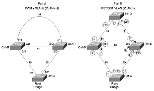
Figure 7-29 illustrates the case of an IDF MST switch. Cat-B has been put back into service and the generic 802.1Q switch has been relocated to the IDF wiring closet in place of Cat-D (it is called Sw-D).
Figure 7-29. IDF MST Switch Load Balancing

In this case, both uplink ports on Sw-D must be Forwarding. However, to ensure this behavior, one of Sw-D's ports must become a Root Port and the other must become a Designated Port. This can be accomplished by increasing the cost on Cat-C:Port-2/2 and Cat-C:Port-2/3 enough to force Cat-C:Port-2/1 into the Blocking state (because Sw-D:Port-2 has the most attractive port for the Cat-C to Sw-D segment). Now that the MST switch has all inter-switch ports in the Forwarding state, load balancing can be addressed. In this case, Cat-B should be configured to forward half of the VLANs (for example, the even VLANs) while Cat-C handles the other half (the odd VLANs). This can be done by increasing (or decreasing) the Path Cost on Ports 2/3 of Cat-B and Cat-C for alternating VLANs.
Note
Note that the Path Cost on Cat-C:Port-2/3 needs to be set between 20 and 37 for the topology to work as described in Figure 7-29. If it were set lower, Cat-C:Port-2/1 would have a lower Root Path Cost than Sw-D:Port-2, causing Sw-D:Port-2 to enter the Blocking state. On the other hand, if Cat-C:Port-2/3's Path Cost were set to higher than 37, Cat-C:Port-2/1 would become the Root Port for Cat-C, causing Cat-C:Port-2/3 to enter the Blocking state.
EAN: N/A
Pages: 223