Campus Design Models
Although a myriad of permutations and variations exist, most campus designs can be grouped into three categories:
Traditional router and hub model
Campus-wide VLANs model (also known as flat earth and end-to-end VLANs)
Multilayer model
The sections that follow go into more detail on each of these campus design models.
Router and Hub Model
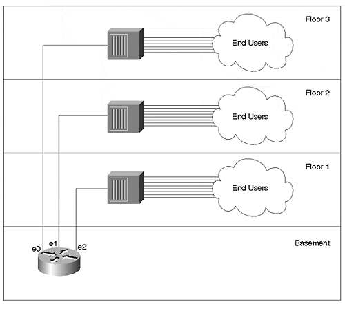
Figure 14-4 illustrates the traditional router and hub model.
Figure 14-4. Router and Hub Model

The traditional router and hub model uses Layer 1 hubs in IDF/access wiring closets. These connect back to unique ports on routers located in MDF/distribution closets. Several options are available for the campus core. In one approach, the distribution layer routers directly interconnect to form the network core/backbone. Because of its reliability and performance, an FDDI ring has traditionally been the media of choice for these connections. In other cases, some network designers prefer to form a collapsed backbone with a hub or router.
There are several advantages to the router and hub model as well as several reasons why most new designs have shied away from this approach. Table 14-1 lists the advantages and disadvantages of the router and hub model.
Table 14-1. Advantages and Disadvantages of the Router and Hub Model
Advantage
Disadvantage
Its reliance on routers makes for very good broadcast and multicast control.
Shared-media hubs do not offer enough bandwidth for modern applications. For example, in Figure 14-2, each floor must share a single 10 Megabit segment (factor in normal Ethernet overhead and these segments become extremely slow).
Because each hub represents a unique IP subnet or IPX network, administration is straightforward and easy to understand.
This design generally uses software-based routers that cannot keep up with increasing traffic levels.
Given moderate levels of traffic and departmental servers located on the local segment, the router and hub model can yield adequate performance.
Traffic patterns have changed, invalidating the assumption that most traffic would remain local. As a result, the campus-wide VLANs model became popular.
The hardware for this model is readily available and inexpensive.
The chief advantage of this approach is the simplicity and familiarity that it brings to campus network design and management. The primary disadvantage is the limited bandwidth that this shared-media approach offers. The multilayer design model discussed later attempts to capitalize on the simplicity of the router and hub model while completely avoiding the limited bandwidth issue through the use of Layer 2 and 3 switching technology.
Campus-Wide VLANs Model
As people began to notice their router and hub networks struggling to keep up with traffic demands, they looked for alternate approaches. Many of these organizations decided to implement campus-wide VLANs, also known as the flat earth and end-to-end VLAN approach to network design.
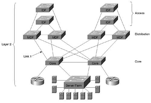
Campus-wide VLANs strive to eliminate the use of routers. Because routers had become a significant bottleneck in campus networks, people looked for ways to minimize their use. Because broadcast domains still needed to be held to a reasonable size, VLANs were used to create logical barriers to broadcasts. Figure 14-5 illustrates a typical campus-wide VLANs design.
Figure 14-5. Campus-Wide VLAN Model

Figure 14-5 uses Layer 2 switching throughout the entire network. To provide communication between VLANs, two routers have been provided using the router-on-a-stick configuration (see Chapter 11).
Advantages of Campus-Wide VLANs
As the paragraphs that follow attest, there are some alluring aspects to the flat earth approach.
First, the campus-wide VLANs model allows network designers to create a direct Layer 2 path from end stations to the most commonly used servers. By deploying Layer 2 switching in all three layers of the access/distribution/core model, campus-wide VLANs should dramatically increase available bandwidth.
The second advantage of the campus-wide VLANs model is that VLANs can be used to provide logical control over broadcast domains and, therefore, subnets. Some platforms allow the switches to automatically detect what VLAN an end station should be assigned to, requiring no administration for adds, moves, and changes. Other schemes allow for more centralized control over VLAN assignments and strive to make the administration as easy as possible. For example, vendors can provide demos of glitzy products that allow you to drag-and-drop end users into VLANs. Other examples include Cisco's Virtual Management Policy Server (VMPS) that makes VLAN assignments based on MAC addresses and User Registration Tool (URT) that uses NT directory services (VMPS and URT are discussed in the section "VMPS and Dynamic VLANs: Advanced Administration" of Chapter 5, "VLANs").
The third advantage of campus-wide VLANs is that traffic only goes through a router if it needs to cross VLAN boundaries. If a user in the Finance VLAN needs to access the Finance server (located in the same VLAN), no routers are involved. However, if this user needs to occasionally access a server in the Marketing VLAN, a router is used. Servers can even be directly connected to multiple VLANs through the use of ISL or LANE NICs, further reducing the requirement for routers. For example, the server in the Marketing VLAN can be fitted with an ISL NIC to allow direct, Layer 2 access from the Finance VLAN.
Finally, this centralized use of routing can make it much easier to configure access lists and security in the network. For example, consider the case of a college network where two VLANs exist: students and professors. These two VLANs might span dozens of buildings, but because of the centralized routing typically used with campus-wide VLANs, access lists might only need to be configured on a pair of routers. On the other hand, if every building on campus connected to the campus backbone through a router, the network might require hundreds of access lists scattered across many dozens of routers.
The end result: you have the speed of Layer 2, the flexibility of VLANs, and you have avoided the "slowness" of the router.
Disadvantages of Campus-Wide VLANs
There are also some significant downsides to the campus-wide VLANs model:
Management difficulties
Lack of logical structure
Large and overlapping Spanning Tree domains
It is easy for a problem in one VLAN to deplete bandwidth in all VLANs across trunk links
Many networks using campus-wide VLANs must resort toeliminating all redundancy to achieve network stability
Lack of scalability
Most modern traffic violates the "stay in one subnet" rule employed by the campus-wide VLAN model
Modern routers are not a bottleneck
The paragraphs that follow provide more detailed coverage of each of these disadvantages.
Management of these networks can be much more difficult and tedious than originally expected. The router and hub design had the logical clarity of one subnet per wiring closet. Conversely, many networks using campus-wide VLANs have developed into a confusing mess of VLAN and Layer 3 address assignments.
Another downside to campus-wide VLANs is that the lack of logical structure can be problematic, especially when it comes to troubleshooting. Without a clearly defined hierarchy, it is very difficult to narrow down the source of each problem. Before each troubleshooting session, valuable time can be wasted trying to understand the constantly changing VLAN structure.
Also, campus-wide VLANs result in large and overlapping Spanning Tree domains. As discussed in Chapter 6, "Understanding Spanning Tree," and Chapter 7, "Advanced Spanning Tree," STP uses a complex set of evaluations that elect one central device (the Root Bridge) for every VLAN. Other bridges and switches then locate the shortest path to this central bridge/switch and use this path for all data forwarding. The Spanning-Tree Protocol is extremely dynamic if the Root Bridge (or a link to the Root Bridge) is "flapping," the network continuously vacillates between the two switches acting as the Root Bridge (disrupting traffic every time it does so). Large Spanning Tree domains must use very conservative timer values, resulting in frustratingly slow failover performance. Also, as the size and number of the Spanning Tree domains grow, the possibility of CPU overload increases. If a single device in a single VLAN falls behind and opens up a loop, this can quickly overload every device connected to every VLAN. The result: network outages that last for days and are difficult to troubleshoot.
Yet another downside to campus-wide VLANs is that the wide use of trunk links that carry multiple VLANs makes the Spanning Tree problems even worse. For example, consider Link 1 in Figure 14-5, a Fast Ethernet link carrying VLANs 1 15. Assume that the CPU in a single switch in VLAN 1 becomes overloaded and opens up a bridging loop. Although the loop might be limited to VLAN 1, this VLAN's traffic can consume all of the trunk's capacity and starve out all other VLANs. This problem is even worse if you further assume that VLAN 1 is the management VLAN. In this case, the broadcasts caught in the bridging loop devour 100 percent of switch's CPU horsepower throughout the network. As more and more switch CPUs become overloaded, more and more VLANs experience bridging loops. Within a matter of seconds, the entire network "melts down."
An additional problem with the campus-wide VLAN model is that, to avoid these Spanning Tree and trunking problems, many campus-wide VLAN networks have had to resort to eliminating all redundant paths just to achieve stability. To solve this problem, redundant links can be physically disconnected or trunks can be pruned in such a way that a loop-free Spanning Tree is manually created. In either case, this makes every device in the network a single point of failure. Most network designers never intend to make this sort of sacrifice when they sign up for a flat earth design. Without routers, there are no Layer 3 "barriers" in the network and it becomes very easy for problems to spread throughout the entire campus.
Furthermore, campus-wide VLANs are not scalable. Many small networks have been successfully deployed using the campus-wide VLAN design. Initially, the users of these networks are usually very happy with both the utility and the bandwidth of their new infrastructure. However, as the network begins to grow in size, the previously mentioned problems become more and more chronic.
Yet another downside to campus-wide VLANs is that it is harder and harder to bypass routers, the very premise that the entire campus-wide VLANs scheme was built upon. As traffic patterns have evolved from departmental servers on the local segment to enterprise servers located in a centralized server farm, it has become very difficult to remove routers from this geographically dispersed path. For example, it can be difficult to connect an enterprise web server to 20 or more VLANs (subnets) without going through a router. A variety of solutions such as ISL, 802.1Q, and LANE NICs have become available; however, these have generally produced very disappointing performance. And, as mentioned earlier, these NICs request the server to process all broadcasts for all VLANs, robbing it of valuable and expensive CPU cycles. Also, the multiple-VLAN NICs have been fraught with other problems such as slow initialization time, a limited number of VLANs, and unexpected server behavior.
Finally, another basic premise of the campus-wide VLAN strategy is no longer true. Specifically, routers are now as fast (or nearly as fast) as Layer 2 switches. Although this equivalent performance generally comes at a price premium, it is no longer worthwhile to go to such great lengths to avoid Layer 3 routing.
Practical Advice Regarding Campus-Wide VLANs
I have implemented several networks utilizing the campus-wide VLAN approach. Prior to 1998, routers were simply too slow to place them in the middle of burgeoning campus traffic levels. Although I often had this nagging feeling about the lack of Layer 3 hierarchy, I jumped on the bandwagon with everyone else. In short, there simply didn't seem to be another option. However, with the advent of Layer 3 switching, I see fewer and fewer compelling uses for campus-wide VLANs.
Before leaving you with the feeling that everyone using campus-wide VLANs hates it, I should also point out that there are some fairly large networks utilizing this model with great success. Whether it is because their traffic patterns still adhere to the 80/20 rule or they like to take advantage of the drag-and-drop approach to VLANs, some network administrators firmly support this style of network design.
However, I have talked to far more clients that have struggled to produce stable and scalable networks using this model. For many users, the disadvantages discussed earlier are far too debilitating to justify the advantages of the campus-wide VLAN design.
Tip
Carefully evaluate the downsides of the campus-wide model before designing your network in this manner. Although some users are very happy with this approach to campus design, most have been disappointed with the stability and scalability.
Multilayer Model
The multilayer model strives to provide the stability and scalability of the router and hub model while also capturing the performance of the campus-wide VLANs model. This approach takes full advantage of hardware-based routing, Layer 3 switching, to put routing back into its rightful place. However, it does not ignore Layer 2 switching. In fact, it seeks to strike the optimal balance Layer 3 switching is used for control, whereas Layer 2 switching is used for cost-effective data forwarding.
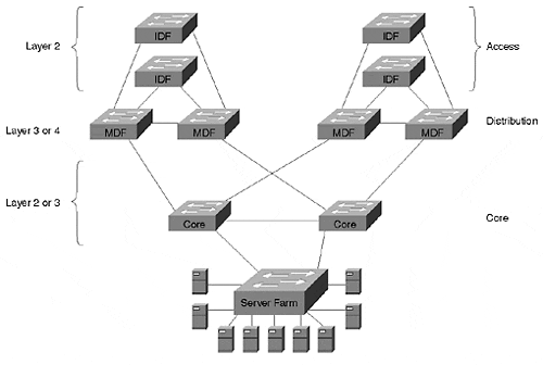
Figure 14-6 illustrates a sample network using the multilayer model.
Figure 14-6. Multilayer Model

Each IDF/MDF cluster forms a separate module in the design. Figure 14-6 shows two modules. The access layer IDF switches use Layer 2 forwarding to provide large amounts of cost-effective bandwidth. The distribution layer MDF switches provide the Layer 3 control that is required in all large networks. These IDF/MDF modules then connect through a variety of Layer 2 or Layer 3 cores.
Tip
The multilayer model combines Layer 2 and Layer 3 processing into a cohesive whole. This design has proven to be highly flexible and scalable.
In general, the multilayer model is the recommended approach for enterprise campus design for several reasons.
First, the use of routers provides adequate Layer 3 control. In short, this allows all of the benefits discussed in the "Advantages of Routing" section to accrue to your network. Without listing all of these advantages again, a multilayer design is scalable, flexible, high performance, and easy to manage.
Second, as its name suggests, the multilayer model offers hierarchy. In hierarchical networks, layers with specific roles are defined to allow large and consistent designs. As the next section discusses, this allows each layer of the access/distribution/core model to meet unique and specific requirements.
Third, this approach is very modular. There are many benefits to a modular design, including the following:
It is easy to grow the network.
The total available bandwidth scales as additional modules are added.
Modular networks are easier to understand, troubleshoot, and maintain.
The network can use cookie cutter configurations. This consistency saves administrative headaches while also reducing the chance of configuration errors.
It is easier to migrate to a modular network. The old network can appear as another module (although it does not have the consistent layout and configurations of modules in the new network).
Modular networks allow consistent and deterministic traffic patterns.
Modular designs promote load balancing and redundancy.
It is much easier to provide fast failover in a consistent, modular design than it is in less structured designs. Because the topology is constrained and well defined, both Layer 2 and Layer 3 convergence benefit.
Modular networks allow technologies to be easily substituted for one another. Not only does this allow organizations more freedom in the initial design (for example, the core can be either Ethernet or ATM), it makes it easier to upgrade the network in the long run.
EAN: N/A
Pages: 223