Router-on-a-Stick
Early VLAN designs relied on routers connected to VLAN-capable switches in the manner shown in Figure 11-1.
Figure 11-1. Router-on-a-Stick Design

In this approach, traditional routers are connected via one or more links to a switched network. Figure 11-1 shows a single link, the stick, connecting the router to the rest of the campus network. Inter-VLAN traffic must cross the Layer 2 backbone to reach the router where it can move between VLANs. It then travels back to the desired end station using normal Layer 2 forwarding. This "out to the router and back" flow is characteristic of all router-on-a stick designs.
Figure 11-1 portrays the router connection in a general sense. When discussing specific options for linking a router to a switched network, two alternatives are available:
One-link-per-VLAN
Trunk-connected router
One-Link-per-VLAN
One of the earliest techniques for connecting a switched network to a router was the use of one-link-per-VLAN as shown in Figure 11-2.
Figure 11-2. One-Link-per-VLAN
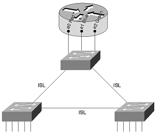
In this case, the switched network carries three VLANs: Red, Blue, and Green. Inter-Switch Link (ISL) trunks are used to connect the three switches together, allowing a single link to carry all three VLANs. However, connections to the router use a separate link for every VLAN. Figure 11-2 illustrates the use of 10 Mbps router ports; however, Fast Ethernet, Gigabit Ethernet, or even other media such as Asynchronous Transfer Mode (ATM) or Fiber Distributed Data Interface (FDDI) can be used.
There are several advantages to using the one-link-per-VLAN approach:
It allows existing equipment to be redeployed in a switched infrastructure, consequently saving money.
It is simple to understand and implement. Network administrators do not have to learn any new concepts or configuration commands to roll out the one-link-per-VLAN approach.
Because it relies of multiple interfaces, it can provide high performance.
Furthermore, notice that every router interface is unaware of the VLAN infrastructure (they are access ports). This allows the router to utilize normal processing to move packets between VLANs. In other words, there is no additional processing or overhead.
Although there are advantages to the one-link-per-VLAN design, it suffers from several critical flaws:
It can require more interfaces than is practical. In effect, this limits the one-link-per-VLAN approach to networks carrying less than 10 VLANs. Trying to use this model with networks that carry 15 or more VLANs is generally not feasible because of port-density and cost limitations.
Although it can initially save money because it allows the reuse of existing equipment, it can become very expensive as the number of VLANs grows over time. Keep in mind that every VLAN requires an additional port on both the router and the switch.
It can become difficult to maintain the network over time. Although the one-link-per-VLAN design can be simple to initially configure, it can become very cumbersome as the number of VLANs (and therefore cables) grows.
In short, the downside of the one-link-per-VLAN approach can be summarized as a lack of scalability. Therefore, you should only consider this to be a viable option in networks that contain a small number of VLANs.
Tip
The one-link-per-VLAN model can be appropriate in networks with a limited number of VLANs.
Example 11-1 presents a possible configuration for the router in Figure 11-2.
Example 11-1 One-Link-Per-VLAN Router Configuration
interface Ethernet0 ip address 10.1.1.1 255.255.255.0 ! interface Ethernet1 ip address 10.1.2.1 255.255.255.0 ipx network 2 ! interface Ethernet2 ip address 10.1.3.1 255.255.255.0 appletalk cable-range 300-310 304.101 appletalk zone ZonedOut ipx network 3
The configuration in Example 11-1 provides inter-VLAN routing services for three VLANs:
VLAN 1 is connected to the Ethernet0 interface and is only using the IP protocol.
VLAN 2 is linked the Ethernet1 interface and uses the IP and IPX protocols.
VLAN 3 is linked to the Ethernet2 interface and supports three network layer protocols: IP, IPX, and AppleTalk.
Notice that the router is unaware of VLANs directly it sees the network as three normal segments.
Trunk-Connected Routers
As technologies such as ISL became more common, network designers began to use trunk links to connect routers to a campus backbone. Figure 11-3 illustrates an example of this approach.
Figure 11-3. Trunk-Connected Router
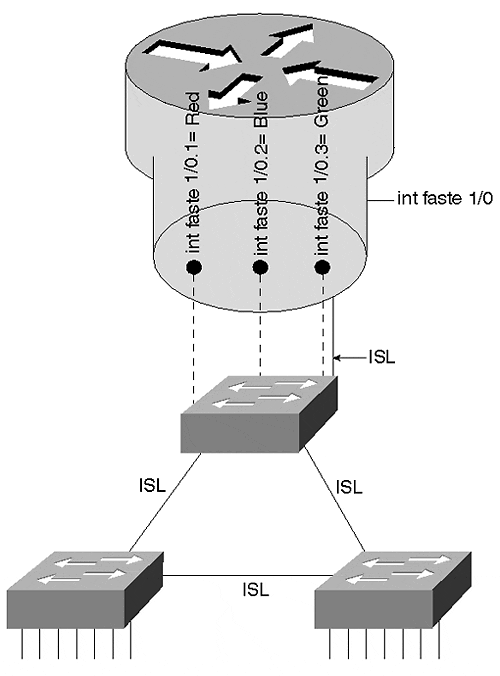
Although any trunking technology such as ISL, 802.1Q, 802.10, LAN Emulation (LANE), or MPOA can be used, Ethernet-based approaches are most common (ISL and 802.1Q). Figure 11-3 uses ISL running over Fast Ethernet. The solid lines refer to the single physical link running between the top Catalyst and the router. The dashed lines refer to the multiple logical links running over this physical link.
The primary advantage of using a trunk link is a reduction in router and switch ports. Not only can this save money, it can reduce configuration complexity. Consequently, the trunk-connected router approach can scale to a much larger number of VLANs than the one-link-per-VLAN design.
However, there are disadvantages to the trunk-connected router configuration, including the following:
Inadequate bandwidth for each VLAN
Additional overhead on the router
Older versions of the IOS only support a limited set of features on ISL interfaces
With regard to inadequate bandwidth for each VLAN, consider, for example, the use of a Fast Ethernet link where all VLANs must share 100 Mbps of bandwidth. A single VLAN could easily consume the entire capacity of the router or the link (especially if there is a broadcast storm or Spanning Tree problem).
With regard to the additional overhead on the router caused by using a trunk-connected router, not only must the router perform normal routing and data forwarding duties, it must handle the additional encapsulation used by the trunking protocol. Take ISL running on a 7500 router as an example. Cisco's software-based routers have a number of different switching modes, a term that Cisco uses to generically refer to the process of data forwarding in a router.
Note
Don't confuse the term switching here with how it normally gets used throughout this book. These software-based routers use the term switching to refer to the process of forwarding frames through the box, regardless of whether the frames are routed or bridged.
Every Cisco router supports multiple forwarding techniques. Although a full discussion of these is not appropriate for a campus-oriented book, it is easiest to think of them as gears in an automobile transmission. For example, just as every car has a first gear, every Cisco router (including low-end routers such as the 2500) supports something called Process Switching. Process Switching relies on the CPU to perform brute-force routing on each and every packet. Just as first gear is useful in all situations (uphill, flat roads, rain, snow, dry, and so on), Process Switching can route all packets and protocols. However, just as first gear is the slowest in a car, Process Switching is slowest forwarding technique for a router.
Every Cisco router also has a second gear this is referred to as Fast Switching. By taking advantage of software-based caching techniques, it provides faster data forwarding. However, just as second gear is not useful in all situations (going up a steep hill, starting away from a traffic signal, and so on), Fast Switching cannot handle all types of traffic (for example, many types of SNA traffic).
Finally, just as high-end automobiles offer fancy six-speed transmissions, high-end Cisco routers offer a variety of other switching modes. These switching modes go by names such as Autonomous Switching, Silicon Switching, Optimum Switching, and Distributed Switching. Think of these as gears three, four, five, and six (respectively) in a Ferrari's transmission they can allow you to move very quickly, but can be useful only in ideal conditions and very limited situations (that is, dry pavement, a long country road, and no police!).
Getting back to the example of an ISL interface on a 7500 router, 7500 routers normally use techniques such as Optimum Switching and Distributed Switching to achieve data forwarding rates from 300,000 to over 1,000,000 packets per second (pps).
Note
Several performance figures are included in this chapter to allow you to develop a general sense of the throughput you can expect from the various Layer 3 switching options. Any sort of throughput numbers are obviously highly dependent on many factors such as configuration options, software version, and hardware revision. You should not treat them as an absolute indication of performance (in other words, "your mileage may vary").
However, when running ISL, that interface becomes limited to second gear Fast Switching. Because of this restriction, ISL routing is limited to approximately 50,000 to 100,000 pps on a 7500 (and considerably less on many other platforms).
Some of this limitation is due to the overhead of processing the additional 30-byte ISL encapsulation. With older interfaces such as the Fast Ethernet Interface Processor (FEIP), this can be especially noticeable because the second CRC (cyclic redundancy check) contained in the ISL trailer must be performed in software. In the case of newer interfaces such as the PA-FE (Fast Ethernet port adapter for 7200 and VIP interfaces) or the FEIP2, hardware assistance has been provided for tasks such as the ISL CRC. However, even in the case of the PA-FE and the FEIP2, the Fast Switching limitation remains.
Tip
The RSM Versatile Interface Processor (VIP) (the card into which you put port adapters) is not the same as a 7500 VIP. It is port adapters themselves that are the same in both platforms.
Note that switching routers such as the Catalyst 8500s use ASICs to handle ISL and 802.1Q encapsulations, effectively removing the overhead penalty of trunk links. However, devices such as the 8500 are rarely deployed in router-on-a-stick configurations. See the section on 8500-style switching routers later in this chapter.
Tip
Software-based routers containing Fast Ethernet interfaces, such as the 7500, 7200, 4000, and 3600, are limited to Fast Switching speeds for ISL operations. ASIC-based routers such as the Catalyst 8500 do not have this limitation and can perform ISL routing at wire speed.
The third disadvantage of the trunk-connected router design is that older versions of the IOS only support a limited set of features on ISL interfaces. Although most limitations were removed in 11.3 and some later 11.2 images, networks using older images need to carefully plan the inter-VLAN routing in their network. Some of the more significant limitations prior to 11.3 include the following:
Support for only IP and IPX. All other protocols (including AppleTalk and DECnet) must be bridged. Inter-VLAN bridging is almost always a bad idea and is discussed later in the section "Integration between Routing and Bridging."
IPX only supports the novell_ether encapsulation (Novell refers to this as Ethernet_802.3).
HSRP is not supported. This can make it very difficult or impossible to provide default gateway redundancy.
Secondary IP addresses are not supported.
Tip
ISL interfaces prior to 11.3 (and some later versions of 11.2) only support a limited set of protocols and features. 11.3+ code addresses all four of the issues mentioned in the preceding list.
As discussed in Chapter 9, "Trunking with LAN Emulation," subinterfaces allow Cisco routers to create multiple logical partitions on a single physical interface. Just as subinterfaces allow each ELAN on a single ATM interface to belong to its own logical grouping, subinterfaces on Fast Ethernet (or other media) interfaces allow a logical partition for each VLAN. If the physical interface is Fast Ethernet1/0 (this is also called the major interface), subinterfaces can use designations such as Fast Ethernet1/0.1, Fast Ethernet1/0.2, and Fast Ethernet1/0.3. For example, the configuration in Example 11-2 configures a Fast Ethernet port to perform ISL routing for three VLANs.
Example 11-2 ISL Router-on-a-Stick Configuration
interface FastEthernet1/0 no ip address ! interface FastEthernet1/0.1 encapsulation isl 1 ip address 10.1.1.1 255.255.255.0 ! interface FastEthernet1/0.2 encapsulation isl 2 ip address 10.1.2.1 255.255.255.0 ipx network 2 ! interface FastEthernet1/0.3 encapsulation isl 3 ip address 10.1.3.1 255.255.255.0 appletalk cable-range 300-310 304.101 appletalk zone ZonedOut ipx network 3
The major interface contains no configuration statements (the no ip address command appears by default). One subinterface is created per VLAN. Each subinterface must receive the encapsulation isl vlan command to specify the VLAN to associate with that subinterface. (This must be done before the IP and AppleTalk parameters are configured, otherwise the router generates an error message.) Commands specific to each VLAN are also placed on the subinterface. For example, the first subinterface (Fast Ethernet1/0.1) is configured to handle VLAN 1. Because only an IP address is specified on this subinterface, the router does not perform services for other protocols that might be present in VLAN 1. On the other hand, subinterface 1/0.3 is used to handle traffic for IP, IPX, and AppleTalk.
Notice that this router must be running 11.3+ code to support the AppleTalk protocol. Also notice that this configuration is functionally identical to the example presented in the "One-Link-per-VLAN" section.
Tip
Although the router allows the subinterface numbers and VLAN numbers to differ, using the same numbers provides easier maintenance. For example, configure VLAN 2 on subinterface X.2 (where X equals the major interface designation).
When to Use the Router-On-A-Stick Design
In general, the router-on-a-stick approach to inter-VLAN routing is most appropriate when other options are not available. This is not to say that the router-on-a-stick design is a poor choice, it is only a reflection that other options tend to provide higher throughput and functionality. Also, because the router-on-a-stick technique functions as if the router were sitting on the edge of the network (at least as far as the Layer 2 network is concerned), it tends to be less tightly integrated with the rest of the campus network. Newer approaches, such as MLS and the 8500s, seek to place routing in the middle of the network where it can have a greater influence on the overall scalability and stability of the network. However, before looking into MLS and 8500 technology, the next section looks at Cisco's first attempt to provide a more integrated approach to inter-VLAN routing the Catalyst 5000 Catalyst Route Switch Module (RSM).
EAN: N/A
Pages: 223
- Article 332 Mineral-Insulated, Metal-Sheathed Cable Type MI
- Article 427: Fixed Electric Heating Equipment for Pipelines and Vessels
- Article 500 Hazardous (Classified) Locations, Classes I, II, and III, Divisions 1 and 2
- Example No. D4(a) Multifamily Dwelling
- Example No. D4(b) Optional Calculation for Multifamily Dwelling