Bridging Protocols
|
Bridging is a method of connecting individual network segments so that they look like a single LAN. Bridging takes place at Layer 2 of the OSI model, as opposed to routing, which takes place at Layer 3. In Figure 9.5, you can see that bridging occurs at Layer 2 and routing at Layer 3.
There are situations where traffic must be bridged rather than routed. For starters, some network protocols cannot be routed and must be bridged. We will take a look at several of those shortly. With Ethernet networks, bridging is a common method of controlling collisions and reducing contention for the media. If you haven’t heard of Ethernet switches over the last few years, you must not have been paying attention, because they’re everywhere! But that flashy Ethernet switch is really nothing more than a multi-port bridge (on steroids, of course). Its operation is similar to that of the transparent bridges (discussed shortly).
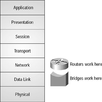
Figure 9.5: OSI-model bridge routing
Since bridges operate at Layer 2 rather than Layer 3 of the OSI model, they don’t see all of the protocol-dependent traffic that routers have to deal with. For example, IP and IPX packets are really indistinguishable to a bridge. IP and IPX are Layer 3 specifications, and the bridge really doesn’t care about their differences. The bridge simply focuses on the Layer 2 frames and avoids the hassle of looking any further.
Bridging creates a single, extended, data-link network. This is often referred to as a flat network. With Cisco IOS, all routable protocols can be bridged. However, don’t think that this is an easy shortcut to avoid routing. Bridging creates its own special concerns. For example, bridges forward broadcasts while routers block them, which means that while 1,500 workstations will work nicely in a routed network, they may melt the wire with broadcasts alone in a bridged one.
Let’s take a quick look at some situations where you have to bridge. Some protocols cannot be routed. In their specifications, they simply do not provide for Layer 3 network addressing. That means they must share a common data-link network (Layer 2) to communicate, which calls for bridging. These non-routable protocols are
-
LAT (Local Area Transport)
-
MOP (Maintenance Operation Protocol)
-
NetBIOS
Transparent Bridging
A transparent bridge can connect two or more network segments into a single data-link LAN. It is called a transparent bridge because the devices on the network are unaware that the bridge is even there. The bridge simply listens to frames and passes them along. It does not address, modify, or receive frames. The bridge really is transparent to the devices on the network.
Transparent bridging is generally used with Ethernet. To be transparent to network devices, the bridge performs three functions:
-
Learning MAC addresses
-
Forwarding packets
-
Filtering packets
These functions allow the bridge to act transparently. Additionally, with multiple bridges, there is the possibility of an endless loop, so the bridge is required to perform a fourth function:
-
Avoiding loops
Let’s discuss each of these functions in detail.
Learning MAC Addresses
When you hook a transparent bridge to an Ethernet segment, it will actually receive all frames transmitted on that segment (remember the MA—Multiple Access in CSMA/CD). Now, suppose you have the bridge illustrated in Figure 9.6.
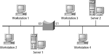
Figure 9.6: Transparent bridge
When Workstation 1 is communicating with Server 1, the bridge overhears all of this traffic on its E0 interface. It quietly notes the source MAC address of each frame received on E0 and enters those addresses into a table as originating from E0. It does the same for all traffic received by its E1 interface. Pretty soon, the bridge will have a fairly comprehensive database of all attached devices (their MAC addresses) out each of its interfaces. The bridge updates the database each time it receives a frame to keep the database current. If the bridge does not see a frame from a device for some predetermined period of time (typically five minutes), the entry for that device is removed from the database.
In this sense, a transparent bridge can accurately be called a learning bridge. By simply listening to traffic, it can quickly learn the location of all network devices on those segments to which it is attached. By continuously updating the database and discarding stale entries, the map of the network remains accurate.
Forwarding Packets
Suppose that in the previous figure (Figure 9.6), you have just turned on the bridge, so it has an empty database. It will immediately begin populating its database with MAC addresses from frames that it receives. Now, suppose that the first frame the bridge receives is the one shown in Figure 9.7.
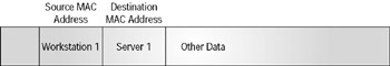
Figure 9.7: Workstation 1–to–Server 1 frame
The bridge now knows that Workstation 1 is out its E0 interface and makes an appropriate entry into its database. However, it still does not know where Server 1 is. The bridge will flood the frame—it will forward the frame out all interfaces except the one on which the frame was received. This ensures that no matter where Server 1 is (and the bridge still does not know where Server 1 is), Server 1 will still receive the frame addressed to it. You know from the Figure 9.4 diagram that this is not necessary, but the bridge does not know that (yet). However, consider what happens next. Server 1 receives the frame from Workstation 1 and generates a reply, as pictured in Figure 9.8.
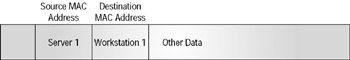
Figure 9.8: Server 1–to–Workstation 1 frame
The bridge receives this frame on its E0 interface, makes an entry for Server 1 in its database, and now knows that both of these devices are located on the same segment. At this point, the transparent bridge can begin the next step: filtering.
Some frames must always be flooded by the bridge; whenever they are received, they must be forwarded to all interfaces (other than the one on which they were received). They include the following types:
-
Frames destined for unknown MAC addresses
-
Broadcast frames
-
Multicast frames
The ramifications of this requirement are discussed in the “Avoiding Loops” section.
Spanning-Tree PortFast is a Cisco enhancement to the Spanning-Tree Protocol (STP) that alters the STP port transition phases, allowing a port to forward data during the listening and learning phases (as opposed to blocking data during this time). If a loop is detected, the switch will immediately block the port. However, there is a danger that it could be too late, because the switch may already be overwhelmed by a broadcast storm. For this reason, PortFast should only ever be used on ports that are connected to a single host, because this ensures that a loop could never occur.
The PortFast configuration is a required solution if you have clients that boot from the network, such as Microsoft’s RIS (Remote Installation Services) clients for operating system imaging. These clients use their network card to search for a Microsoft DHCP, Active Directory, and RIS server immediately upon power-up. The clients will not locate the Microsoft servers if PortFast is not configured on their connected switch ports because of the typical 50-second delay from blocking to forwarding on a Cisco switch.
PortFast is configured using the following commands:
-
CatOS: set spantree portfast mod/port {enable | disable}
-
Cisco IOS: (config-if)# spanning-tree portfast
If you are absolutely certain that all PortFast ports are connected to a single host, you can also implement a Cisco feature called PortFast BPDU Filter, which prevents any PortFast port from sending bridge protocol data units (BPDUs). This prevents the connected host from having to process each BPDU transmitted.
Filtering Packets
Let’s continue with the preceding example in Figure 9.8. Now that the bridge knows the MAC address of Workstation 1 and Server 1 and knows that they are on the same segment (i.e., out the same bridge interface), it no longer needs to flood packets exchanged between those two machines out its other interfaces.
Suppose that now Workstation 1 sends out a packet to Server 2. If the bridge does not recognize the MAC address of Server 2, it will flood the packet. However (assuming that Server 2 is running), it will immediately learn Server 2’s location when it responds to Workstation 1’s request. From that point forward, the bridge will filter (drop) packets between Workstation 1 and Server 1, because they are on the same segment and do not require the bridge’s help to communicate. The bridge will forward frames between Workstation 1 and Server 2, because without the bridge’s help, these two devices would not be able to communicate. Finally, if Workstation 2 addresses a frame to an unknown device, the bridge will flood the frame and hopefully learn the new device’s location when it responds.
The bridge has the following three options whenever it receives a frame:
-
Filter
-
Forward
-
Flood
The MAC address database is kept in cache on the bridge to speed up the decision-making process.
Avoiding Loops
Loops can be good or bad. When they work correctly, redundant paths provide fault tolerance for certain failures. However, when loops do not work correctly, they can cause complete network failure. Consider the network shown in Figure 9.9.
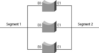
Figure 9.9: Redundant bridges
Three bridges connect Segment 1 and Segment 2. All three bridges hear all frames on each segment; all three bridges also build MAC address databases. However, what if all three bridges forward frames? Suppose a frame on Segment 1 is destined for a device on Segment 2, and all three bridges forward the frame. How will the destination device react when it receives three identical frames? It will probably be a bit confused and require counseling (just kidding).
There is, however, a worse case. Suppose that a broadcast is issued on Segment 1. All three bridges pick it up and flood it to Segment 2. But now, each bridge hears two broadcasts on Segment 2 (one from each of the other two bridges). They are actually copies of the same broadcast, but since these are transparent bridges, there is no way to know that. Each bridge floods the two broadcasts it received on Segment 2 back to Segment 1. Now there are six frames on Segment 1, which becomes 12 frames on Segment 2, which becomes 24 frames on Segment 1. This is called a broadcast storm, and it is a real problem with topological loops and bridges. As this example shows, a single broadcast frame can cause a broadcast storm that will consume all available bandwidth in seconds.
This problem results from the transparent nature of the bridges. Routers tear apart and rebuild packets, and therefore can address issues such as TTL, number of hops, etc. They also handle broadcasts much differently from bridges. However, transparent bridges by definition do not modify packets. They just filter, forward, or flood. Of course, there is a solution.
The Spanning-Tree Protocol (STP) solves this problem. It allows multiple paths to exist for fault tolerance, yet creates a loop-free topology to reduce the risk of broadcast storms. It does this by turning off (blocking) unnecessary interfaces until they are needed. For example, using STP in the preceding example, you may end up with the situation illustrated in Figure 9.10.
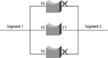
Figure 9.10: Spanning-Tree Protocol implemented
STP turns off (blocks) the interfaces, which can cause loops, and then re-enables the interfaces when necessary for fault tolerance (in case another active path fails, for example).
Cisco supports two STPs for transparent bridging: DEC and IEEE 802.1D. They are not compatible—they will not communicate with each other. The IEEE 802.1D protocol was actually derived from work done by DEC, but nevertheless, they are not compatible.
| Note | Spanning-Tree Protocol and bridging are covered in much more depth in CCNP: Switching Study Guide, also by Sybex. |
STP works in the following manner:
-
All bridges in the Spanning-Tree environment agree on a root bridge. The root bridge is chosen based on the bridge id (a combination of the lowest MAC address and bridge id value).
-
Each bridge discovers all possible paths to the root and then selects the lowest-cost path.
-
Each bridge blocks all other interfaces to prevent loops.
Integrated Routing and Bridging
Integrated routing and bridging (IRB) is an IOS 11.2 feature that allows you to route and bridge the same protocol within a single router. Normally, you cannot have packets cross a single router between routed and bridged interfaces. However, with IRB, you can.
This is accomplished by creating a bridge-group virtual interface (BVI), which represents the bridge group in the routed environment. The interface number of the BVI must correspond to the bridge-group number you wish to include in IRB. The BVI can then be configured and will act just like any other routed interface.
This type of configuration can be useful when you have to connect bridged and routed networks, or perhaps when you need to preserve network addresses (such as IP) yet still route those protocols to a larger internetwork.
Source-Route Bridging
IBM created source-route bridging (SRB) in the mid-1980s to connect corporate Token Rings to their IBM mainframes. With SRB, the source knows the entire route to a destination before any data are transmitted. It is called source-route bridging because the source device gets to choose the entire route to the destination device. SRB is part of the IEEE 802.5 Token Ring specification.
SRB was not designed for large internetworks. The specifications for IBM Token Ring define a maximum of eight rings and seven bridges. The 802.5 specification defines up to 14 rings and 13 bridges.
Types of Explorer Packets
A source device determines the best path to a destination device by sending explorer packets. There are three types of explorer packets:
Local explorer packets Local explorer packets are used to find local destination devices.
Spanning explorer packets Spanning explorer packets are used to find the best route to the final destination.
All-routes explorer packets All-routes explorer packets are used to find all routes to a destination host by checking all rings.
| Note | All-routes explorer packets are also known as all-rings explorer packets, and spanning explorer packets are also known as single-route and limited-route explorer packets. |
The following steps describe how the three types of explorer packets work together to find a route to a destination device:
-
A NetBIOS or SNA device generates a local explorer packet to determine if the destination device is connected to the local ring.
-
If the destination device is not located on the local ring, the transmitting device sends either a spanning or an all-routes explorer packet. (A NetBIOS device sends a spanning explorer packet; an SNA device sends an all-routes explorer packet.)
-
The destination device responds to the explorer packets, which then return to the originating device. By examining the RIF (route information field), the source can determine the route to take to the destination.
From that point forward, the source determines the path, hence the name source-route bridging.
Source-Route Transparent Bridging
Source-route transparent bridging (SRT) was introduced by IBM in 1990. In SRT, both SRB and transparent bridging occur within the same device. You can use SRT on Token Ring networks where some devices are doing SRB, but some are not. SRT does not translate between two bridging domains—the SRB and transparent bridging systems do not communicate via the SRT. If the traffic arrives with SRB routing information, SRB is used. If not, transparent bridging is used. Token Ring–to–Ethernet communication is not provided by SRT.
Source-Route Translational Bridging
Source-route translational bridging (SR/TLB) is used when bridging domains must be crossed. With SRT, it was possible to do both SRB and transparent bridging. With SR/TLB, SRB and transparent bridging domains can now communicate. With SRT, communication from Ethernet to Token Ring was not supported. With SR/TLB, that issue can be addressed. SRB generally runs on a Token Ring network, while transparent bridging is generally associated with Ethernet. (Note that SR/TLB is a Cisco IOS feature; it is not an industry standard.)
| Warning | The STP packets used to prevent loops in transparent bridging environments will not cross SRB environments. It is crucial that no redundant paths are configured between the two domains, because STP will not be able to detect and thus disable them. |
When bridging between Ethernet and Token Ring, a number of issues must be addressed:
-
MTU size
-
Lack of support for RIF in Ethernet frames
-
Different systems for MAC addresses
Warning There are significant technical challenges when bridging between dissimilar media. Cisco has documented problems with bridging Novell IPX, DECnet Phase IV, AppleTalk, VINES, XNS, and IP from Token Ring to other media and recommends that these protocols be routed rather than bridged whenever possible.
|
EAN: 2147483647
Pages: 201