Adjusting Daylight Using the Global Illumination System
|
| < Day Day Up > |
|
To adjust daylight, we propose using the system called Daylight. This system integrates two light sources, which simulate sunlight and scattered daylight, with a special animation controller (based on season, time, and the location of the lit object on the Earth's surface) and an auxiliary object (Helper) of the Compass type, which determines the orientation of the object.
| Note | In previous versions of 3ds max there was a similar Sunlight system. For the sake of compatibility, it was retained in 3ds max 5. However, with the addition of the Daylight system, it is of no interest. |
-
Create the daylight illumination system in the viewport on the Top view (Fig. 10.2):
-
Main menu à Create à Light à Daylight
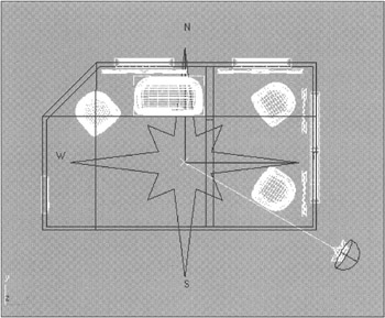
Figure 10.2: Daylight system creation -
Now, turn to the system elements. The compass is the simplest one. The entire illumination system is bound up with this auxiliary object. By default, the North direction coincides with the viewport for the top view. This is logical because it complies with principles accepted in cartography, but if it does not suit you, you can turn the compass as you like. In this case, we want North at the bottom. You can move North by turning the compass or by changing the orientation in the animation controller settings.
The next element is the special animation controller.
-
Select the Daylight system and turn to the animation editing parameters (Fig. 10.3):
-
Control panel à Motion tab à Control Parameters
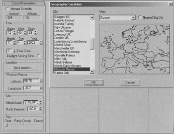
Figure 10.3: Animation controller parameters for the Daylight system -
Now, let's try to find out what's it all about.
The parameters of the Time group determine the moment of time — such as the time of day and the day of the year — for which the lighting is to be rendered. The Time Zone parameter determines the time bias relative to Greenwich Mean Time. This sometimes causes problems, but 3ds max automatically adjusts this parameter according to the system settings. The readings of the system timer at the moment of the daylight system creation are also taken automatically.
| Note | You can find the value of this parameter in the Windows settings. For the English version, it is: Control panel à Date and Time à Time Zone. |
The Daylight Saving Time flag takes into account the summer time difference.
The Location group enables you to enter the values of the latitude and the longitude of the object manually or using the map, where you can select the object's location.
The parameters of the Site group determine the distance to the Sun and sky (Orbital Scale), as well as the orientation (North Direction). The Orbital Scale parameter is not critical, and there is no need to enter the real distance (150 million kilometers). The important thing is that the Sun was never inside the room.
Last, but not least, the Sky group lets you redistribute the energy between the Sun and the sky depending on the weather conditions. Its use is justified only when IES Sun and IES Sky are used as sources of light.
| Note | All parameters can be animated. You can easily animate the change of illumination (for a room or cottage) depending on the time of the day, season, or weather conditions. |
Now, let us examine the parameters of the light sources. To do this, go to the Modify panel (Fig. 10.4).
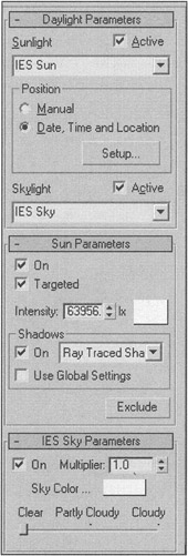
Figure 10.4: Adjustment parameters for Daylight sources
| Note | We have regrouped the rollouts to discuss the most important parameters first. |
The parameters in the Daylight rollout let you select the type of the light sources that will simulate the Sun and the sky. This selection is not big, but it is fundamental. You can use either IES Sun or the standard directional source of light (Direct Light) as the Sun. Similarly, you can use either IES Sky or Skylight as the sky. To use the system to its full advantage, we recommend that you use the IES Sun/IES Sky bond. Why?
The IES prefix stresses that these sources of light comply with the standard of the Illuminating Engineering Society of the U.S.A., which proves the sources' reliability from the physical point of view. In addition, the use of these sources makes the intensiveness of the sunlight dependent on the Sun's position above the horizon, which, in turn, depends on the season, the time of the day, and the nebulosity parameter specified in the IES Sky Parameters rollout. Combining all of these parameters provides realistic illumination conditions.
It is worth mentioning that in 3D-graphics, the notions of "realistic" and "beautiful" do not always go hand-in-hand. The developers of 3ds max know this and provide you with an option to correct any parameters as you like. For example, with daylight you can ignore the automatic settings by switching to the Manual mode.
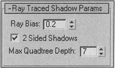
The other rollouts are independent from the type of light source and the shadows that are used. Do not edit them at this stage. The only thing you should do is ensure that the 2 Sided Shadows flag is checked in the Shadows parameters for the Sun.
We have adjusted daylight to 5:00 PM, Moscow time, June 4, 2002.
To continue, it is worth creating a camera and placing it in the room (Fig. 10.5). First, create the camera on the top view, using the Target Camera type.
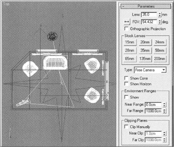
Figure 10.5: Position and parameters of the camera
-
Create the camera:
-
Main menu à Create à Cameras à Target Camera
-
However, it will be more convenient to work with a camera of the Free Camera type. You can switch the camera type on the control panel.
-
You can find the view from the camera by pressing the <C> key and expanding it to full screen (the <Alt>+<W> key combination). In this example, the camera turned out to be set "on the floor." Raise it a little by moving the view in the viewport using the middle mouse button. Make the camera wide-angle by pressing the 35mm button on the control panel.
-
Select all objects and assign one simple material to them. If there are hidden objects in your scene, make them visible beforehand:
-
Context menu à Unhide All
-
-
Open the material editor by pressing the <M> key. Assign the first material called 1-Default by moving it from the preview window (Sample Slot) on the object and selecting the Assign to Selection item.
-
Make the test rendering:
-
Main panel à Quick Render
-
We are sure that you will have nothing but a black square and white spots from the sunlight (Fig. 10.6). So, what is the trouble?
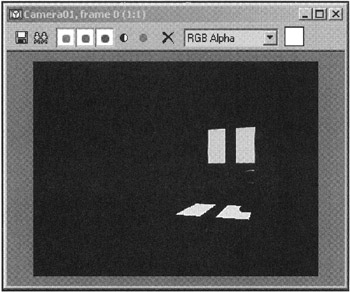
Figure 10.6: Test rendering result
This result occurred because the daylight system is not independent. It is necessary to adjust two additional procedures: Advanced Lighting and Exposure Control.
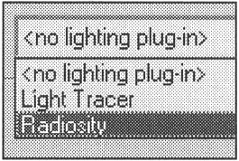
To continue, note that there are two absolutely different global illumination rendering processes integrated in the 3ds max 5: Light Tracer and the so-called Radiosity.
| Note | The term "global illumination" has several synonyms: indirect lighting, reflectance lighting, etc. In the final analysis all of these terms meant the same thing, but "global illumination" was the one that took root. |
Both processes are supposed to solve the same task: render the global illumination. However, they perform it differently. The Light Tracer employs the so-called photon method. A source of light emits particles that, when reflected from the objects' surfaces and gradually attenuated depending on the surface properties, produce a global illumination effect. This method features a considerable drawback: You must re-render the solution for each frame, which greatly increases the final rendering time. However, if you want to light the model using only the coelosphere, this method is preferable.
The Radiosity method is based on rendering the light energy on a surface and redistributing it on the other surfaces. Radiosity divides the surfaces into many small elements through a process called meshing. The smaller the elements, the more accurate the solution, and the more time it takes to render. The rendering time of one frame, however, is barely increased; therefore, the rendering of the camera moving within the room is rather quick. Be aware that any change to the scene geometry, parameters of the sources of light, materials, etc., makes it necessary to repeat the rendering.
In our case, we will use the Radiosity method.
-
Open the Advanced Lighting settings window:
-
Main menu à Rendering à Advanced Lighting
-
-
Select Radiosity in the drop-down menu and press the Start button. The global illumination rendering will start; this may take several minutes.
After the process is completed, you will see the image shown in Fig. 10.7 in the camera viewport. You will obtain almost the same image after the test rendering, and this image will leave much to be desired!
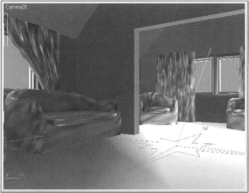
Figure 10.7: Result of Radiosity rendering in the viewport
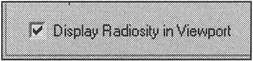
| Note | You will see this image only if you are in the shaded reflection mode in the viewport (Smooth+Highlights) and the Display Radiosity in Viewport flag is checked. |
| Attention | The Use Advanced Lighting flag should be checked in the rendering parameters (Main menu à Rendering à Render à Common Parameters à Advanced Lighting). |
Now, let's improve the appearance of the scene.
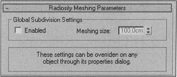
As previously mentioned, the rendering accuracy with the Radiosity method directly depends on the degree to which objects are divided into the triangle elements, or "meshes". In our case, the inner surfaces of the room — the Inner Walls object — are ideal for dividing into many triangle surfaces. 3ds max provides several options for controlling this process. You can assign the dividing degree for all objects in the scene by setting a value in the Radiosity Meshing Parameters rollout in the Advanced Lighting dialog window. This is the simplest, but not the best, solution. Indeed, the curtains and the furniture have a rather complex grid, and the outer walls need no triangulation at all. The second method is to apply the Subdivide modifier, which you can apply to the Inner Walls object. Finally, the third method is to specify the triangulation degree in the properties of the object itself. We recommend that you use this method.
-
Select the Inner Walls object and open its settings:
-
Context menu à Properties
-
-
Turn to the Advanced Lighting tab, uncheck the Use Global Subdivision Settings flag, and specify the dividing value — 10 (Fig. 10.8).
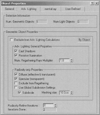
Figure 10.8: Triangulation parameters for the object -
Press OK and start the Radiosity rendering again. You will be warned that the properties of the Inner Walls object were changed. Press the Reset and Continue button to start the rendering from the beginning.
The process will take more time, but the result will be better.
There are several ways to perform further finishing. You can increase the degree of the objects' division, although this is not the best solution from the point of view of the rendering time. You can try to improve the quality (Initial Quality) and refining (Refine Iterations). In this case, you will not have to render everything anew. Finally, you can smooth the "spots" using the Filtering parameter. We obtained a decent result with the parameters shown in Fig. 10.9.
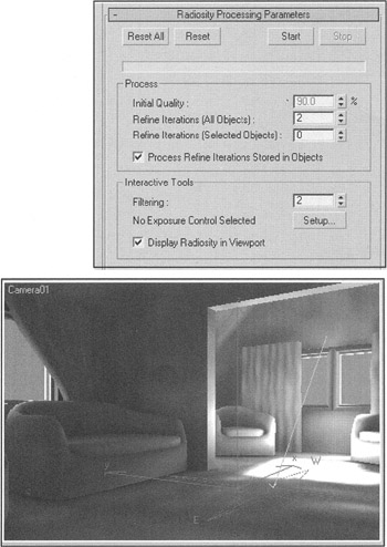
Figure 10.9: Radiosity parameters and rendering result in the viewport
Notice that the spot from the Sun is absolutely white, even too white, whereas the corners of the room are too dark. In reality, you rarely see such contrast. This point needs more detailed consideration.
Today, the most advanced optical device for a human is his eye. Neither photographic camera, nor camera-recorder, TV, or computer display can reproduce the variety of colors and tints available around us. It is not uncommon for a photo made in the most picturesque place, saturated with colors, light, and amazing effects, to become a disappointing piece of paper filled with pale spots and shadows. This problem has become acute as "fully automatic" (and rather expensive) cameras fill the market. This is why we swore off taking pictures of the mountain landscapes; uninitiated people would fail to appreciate their beauty, and those knowing have seen such photos many times! Cinematographers and photographers have been fighting these problems by highlighting dark areas with spotlights and screening direct sunlight. They often substitute overhead spotlights for sunlight to make the dynamic range of the illumination conform with the film speed.
You can solve this problem by employing the exposure control process (Exposure Control). You can open the exposure control settings window from the Advanced Lighting settings menu or from the main menu (Rendering à Environment).
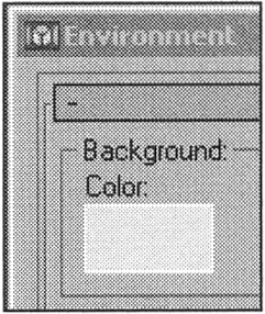
| Tip | Since you have opened this menu, make sure the background color is set to pale blue; it is daytime outside. |
Open Exposure Control and select in the drop-down menu… What? Why are there several choices? Let us try to answer these questions.
The developers of 3ds max offer four procedures for controlling exposure (Fig. 10.10).
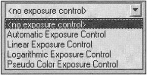
Figure 10.10: Drop-down menu for selecting the exposure control procedure
Let us start from the end of the list by implementing the algorithm with the strangest name: Pseudo Color Exposure Control. The result of its application is no less strange. In our case, everything has been painted red. This happened because this process is not an exposure controller, even if it is placed in this menu. The results of this procedure let you estimate the illumination and the objects' luminance in the scene so you can correctly set the sources of light when the interior design is developed. Try to change some of the parameters in the settings (e.g., increase the Max. value in the Display Range group to 5000) and see what happens. A detailed consideration of this process is beyond the scope of this book, so refer to the "User's Manual" a physics course for more information.
The remaining three processes are variations of one algorithm used to compensate for the imperfection of the displaying devices (e.g., computer display).
-
Automatic Exposure Control creates a bar chart (users of Adobe Photoshop know it well) based on the entire dynamic range and corrects the illumination by expanding the range. This provides excellent results. Unfortunately, it is not applicable to scenes with animation because a separate bar chart is created for each frame, which leads to inadmissible flickering.
-
Linear Exposure Control uses the average brightness value to expand the dynamic range. This algorithm can help improve images with a very low dynamic range. Here, the problems with animation are the same as with Automatic Exposure Control: An average brightness is rendered for each frame.
-
Logarithmic Exposure Control does not use bar charts and is perfect for animation. But you have to pay for it by using a complex setting procedure. This is comparable to a photographic camera with fully manual controls.
In general, all of these exposure controls are easy to understand and use. The only difficulty may be the Physical Scale parameter. Standard sources of light can appear photometrical. The Physical Scale parameter is provided to correctly process the light from the standard sources and convert dimensionless quantities to physical values. There are only photometrical sources of light in our scene, so this parameter does not affect the final result.
We hope that, while reading the above, you have tried all of these processes and noticed how the picture in the viewport changed. We set the parameters as shown in Fig. 10.11. You will need to return to them later.
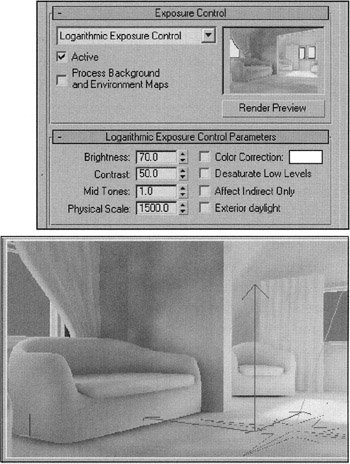
Figure 10.11: Settings for the exposure process parameters and the result in the viewport
Save your work in the file named ![]() Lesson10(room-radiosity).max.
Lesson10(room-radiosity).max.
|
| < Day Day Up > |
|
EAN: N/A
Pages: 136