Linking the Skeleton with the Model
|
| < Day Day Up > |
|
The model of the astronaut has been created, and the skeleton is also ready. Now we will link the skeleton to the model and adjust the effect of the bones using the Skin modifier.
| Note | Some modifiers, including Skin, Unwrap UVW, and Flex, are difficult to call simply "modifiers." These are already "systems" or "packages within a package" that include multiple features and settings. So far, the developers of 3ds max have tried, when defining modifiers, to adhere to the principles laid in the first version. However, we feel that the boundaries of these principles tend to narrow as new versions are released. |
Before you apply the Skin modifier, ensure that all bones are in their correct positions relative to the model; move them, if necessary. This is especially applicable to the finger bones. When we created our model and the bone system, we deliberately made several errors. We thought about correcting these errors but decided to leave them. We will use them to show solutions to problems that may result from inaccurate adjustment of the bones to the model's geometry.
-
Make the SpaceSuit object available for editing (Unfreeze):
-
Contextual menu à Unfreeze All
-
-
Apply the Skin modifier to the SpaceSuit object:
-
Main menu à Modifiers à Animation à Skin
-
On opening the contextual menu of the modifier, we were surprised to find that this menu contained almost all the necessary commands (Fig. 4.19). Praise the 3ds max developers for this! Old habits die hard, however, so we will refer to the commands in the control panel when describing further operations. Nevertheless, we recommend active use of the contextual menu.
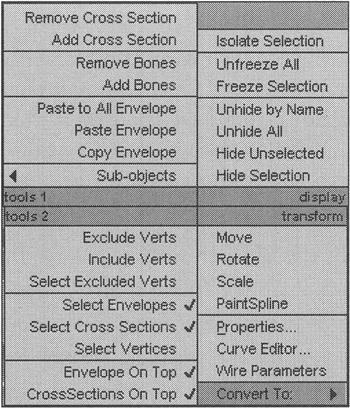
Figure 4.19: Contextual menu of the Skin modifier
3ds max allows any geometrical object, right up to curves (Shapes), to be used as bones. We used objects of the Box type as bones for the boots.
-
Add all of the bones to the list in the Skin modifier:
-
Control panel à Parameters à Add button above the list of bones
-
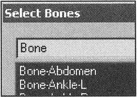
In the selection-by-name dialog, choose all objects whose names begin with "Bone" and press the Select button.
-
| Tip | In the selection-by-name dialog, you can easily select objects by typing in the first letters of their names. |
Select the _BODY object — the oldest in the hierarchy — and move it. We left some vertices of the fingers and hands in place (Fig. 4.20). This shows that the effect of the bones is insufficient on these vertices.
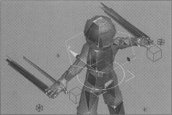
Figure 4.20: Insufficient effect of the skeleton's bones on the model
If everything is OK, don't be too happy; a redundant effect of the bones is as unwanted as an insufficient effect. Now, try to edit the bones' effect on the vertices of the model.
During editing, you repeatedly will have to move the control objects to follow the bones' effect on the model. To do this, you will have to toggle between the SpaceSuit object and the control objects by selecting them in turn. To avoid extra manipulations, we propose that you animate the control objects, properly bending the bones in an intermediate frame.
-
Go to an intermediate frame (e.g., 50) by moving the Time Slider.
-
Press the Auto Key button (Animation recording).
Note The full name of this button is Toggle Auto Key Mode (Toggle on/off animation recording).
-
Move the control objects of the legs and arms by changing the posture of the astronaut (Fig. 4.21).
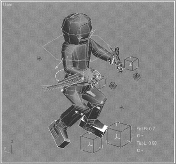
Figure 4.21: Changing the astronaut's posture to control the bones' effect -
Release the Auto Key button.
Now you can change the posture of the object by moving the slider.
-
Go back to the zero frame.
-
Select the SpaceSuit object. Hide the rest of the objects to avoid confusion:
-
Contextual menu à Hide Unselected
-
The Skin modifier allows you to edit the bones' effect on the model's vertices in two ways. The first method, editing each bone's area using the effect area (Envelope), is the simplest but least accurate one. When the skeleton was created, we insisted that you accurately match the bones' sizes to those of the model. The Skin modifier adjusts the effect area based on the sizes of the bones, but not always in the best way. The second method is to directly assign each bone's effect, or "weight" (Weight), to each vertex of the model. This method is more laborious, but more accurate, too. Which is to be applied? Both. The truth is usually somewhere in between; it depends on the task. Let's test this premise.
-
Go to the working mode with the Envelopes:
-
Control panel à Edit Envelopes
-
-
Select the Bone-Abdomen envelope. This can be done in two ways: by selecting the Bone-Abdomen bone from the list, or by clicking with the left mouse button on the gray line corresponding to the center of this bone's envelope.
| Note | The line corresponds to the center of the envelope, not to the bone itself! The envelopes can be moved independent of the bone's position. |
As you see, the envelope consists of two sub-envelopes, or borders (Fig. 4.22, a). The inner envelope defines the area where the bone has 100% effect on the vertices. The outer envelope restricts the bone's effect: The bone does not affect the vertices without it. Between these sub-envelopes, the bone affects the vertices with intermediate values. The bones' effect falloff law (Falloff) is in the drop-down button menu in the Envelope Properties group of the Parameters menu.
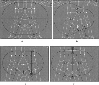
Figure 4.22: Editing the bone-abdomen effect
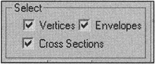
In the display mode in the Wire frame viewport, the bone's effect on the vertices is in color: red corresponds to 100%, blue — 0%. In the Shaded display mode, polygons are colored correspondingly. The Display menu shows what is to be displayed, and how.
The envelope for the abdomen bone is too large. Reduce the size of the outer sub-envelope using the control CrossSection, displayed as "squares".
-
Select one of the "squares" on the outer sub-envelope and move it, thus reducing the bone's effect (Fig. 4.22, b).
-
Achieve symmetry by selecting and moving the square of another cross section (Fig. 4.22, c).
-
Add one more cross section. Move the control vertices of the new cross section to allow this bone to affect the vertices between the legs of the astronaut (Fig. 4.22, d):
-
Control panel à CrossSection à Add
-
Click with the left mouse button approximately in the middle of the envelope.
-
Note that some vertices within the inner sub-envelope are colored in intermediate colors. This shows that other bones, namely, those of the chest and legs, affect these vertices. They also must be edited. At the same time, you should leave overlaps in the envelopes; the spacesuit is thick, so stretches are appropriate.
-
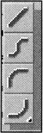
Reduce the effect of the leg bones. Select the envelope of the Bone-Thigh-R bone and edit the control vertices of the cross sections (Fig. 4.23, a).
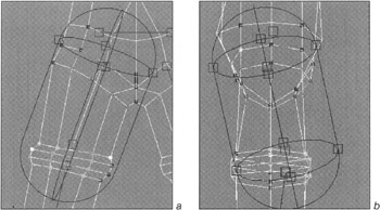
Figure 4.23, a and b: Editing the right thigh envelope
On the front view everything is all right, but the left view clearly shows that this bone ceased to affect the rear vertices of the thigh and knee (Fig. 4.23, b).
-
Correct it by moving the control vertex on the symmetry line of the envelopes (Fig. 4.23, c).
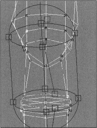
Figure 4.23, c: Editing the right thigh envelope -
Copy the parameters of this bone's envelope into the clipboard using the Copy button on the control panel.

-
Select the envelope of the Bone-Thigh-L bone, paste the copied parameters from the clipboard (Paste), and edit the position of the envelope.
The effect of the other bones of the legs, chest, and arms is edited in the same way.
To edit the bones of the helmet and boots, another method is to be used. These objects are rigid, and the effects of other bones on their vertices can lead to distortions of the geometry.
-
Select the Bone-Helmet envelope.
-
Edit its effect area (Fig. 4.24, a).
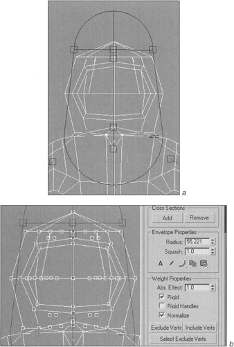
Figure 4.24: Editing the bone-helmet effect -
In the control panel, activate the option for selecting vertices.
-
Select the vertices of the helmet, assign them a weight of 1, and check the Rigid flag (Fig. 4.24, b). Thus, you will point out that only the Bone-Helmet bone will affect these vertices.
The effects of the Bone-Foot-R and Bone-Foot-L for the boots are adjusted in the same way.
Adjust the fingers' effect by combining these two methods.
| Do it yourself | There is another option for editing the weight of the effect — direct drawing (Paint Weights). We propose that you master this feature on your own. We successfully used it to adjust the fingers' effect. For illustration, this can be done in the intermediate frame. |
We encountered another problem: excessive mashing of the model in the oints. It is unlikely that you "survived" the ordeal. Further smoothing can reduce this effect, but you should not fully rely on it.
There are tools within the Skin modifiers that allow you to solve this problem. Use one of them on the left thigh.
Fig. 4.25, a, shows the "mash" we would like to remove. To do this:
-
Go to the zero frame.
-
Select the envelope corresponding to the Bone-Shin-L bone.
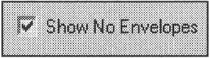
Tip Toggle off the display of the envelopes by checking the Show No Envelopes flag in the Display menu.
-
Select the vertices of the left knee using the lasso (Fig. 4.25, b).
-
Assign the bulge angle deformer on the selected vertices (Bulge Angle Deformer). It is the simplest of the three available. According to the name, its main purpose is to imitate muscles, but in our case it is also suitable:
-
Control panel à Gizmos à Bulge Angle Deformer à Add Gizmo
-
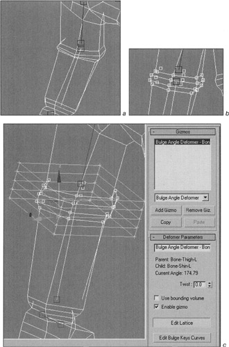
Figure 4.25, a—c: Editing the Bulge Angle Deformer gizmo
The gizmo is formed around the selected vertices (Fig. 4.25, c).
-
Go to the intermediate frame, press the Edit Lattice button, and obtain the desired form by moving the vertices of the gizmo (Fig. 4.25, d).
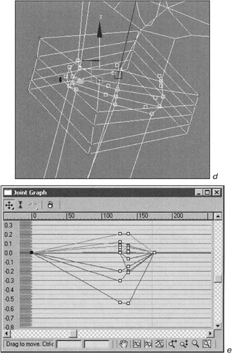
Figure 4.25, d and e: Editing the Bulge Angle Deformer gizmo
You can use the curve editor to adjust the gizmo's vertices according to the angle between the bones (Fig. 4.25, e).
To tell you the truth, this task is minute. Fortunately, after the gizmo of one thigh is adjusted, you can copy the parameters for the other one.
-
Copy the gizmo's parameters into the clipboard by pressing the Copy button.
-
Select the envelope corresponding to the Bone-Shin-R bone.
-
Select the vertices of the right knee and assign the angle deformer on the selected vertices.
-
Use the Paste button to paste the parameters from the clipboard.
-
The same must be done for the elbow joints and for the hip joint (for correct performance of the buttocks).
-
Create the backpack and the communication device (Backpack and Com-Dev objects) and link them to the Bone-Chest bone (Fig. 4.26). Before you do this, unhide all objects in your scene:
-
Context menu à Unhide All
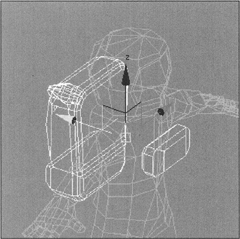
Figure 4.26: Additional objects -
If you followed our advice and made the animation, get rid of it now.
-
Select all objects.
-
Remove the animation keys. First, select and remove the keys from the intermediate frame (ours is 50th), then remove the keys from the zero frame.
Our fully adjusted model is in the ![]() Lesson04-18.max file in the Lessons\ Lesson04\Scenes folder on the CD-ROM.
Lesson04-18.max file in the Lessons\ Lesson04\Scenes folder on the CD-ROM.
|
| < Day Day Up > |
|
EAN: N/A
Pages: 136