8.2 The Four Modeling Layers of the OMG
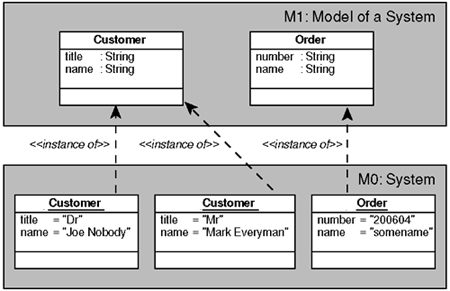
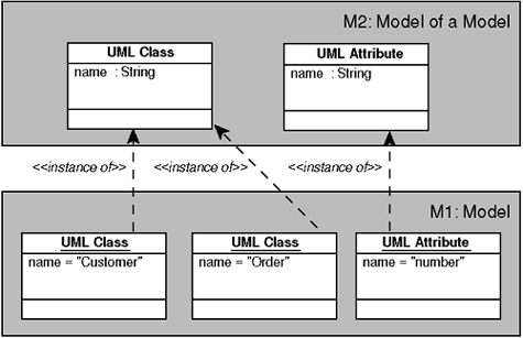
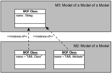
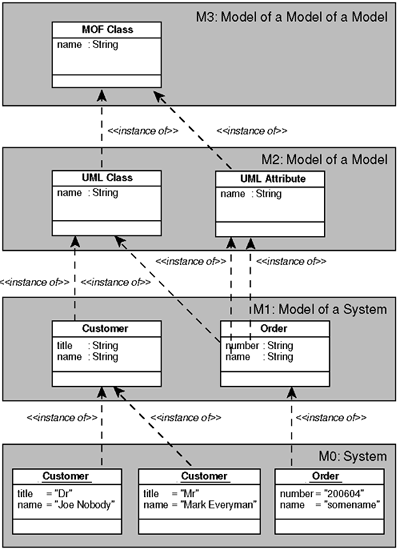
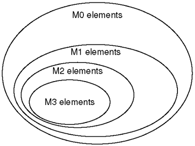
8.2 The Four Modeling Layers of the OMGTo understand the relationships between the various OMG standards that play a role within the MDA framework, you must be aware of the layers of modeling that are defined. The OMG uses a four-layered architecture for its standards. In OMG terminology these layers are called M0, M1, M2, and M3. 8.2.1 Layer M0: The InstancesAt the M0 layer there is the running system in which the actual ("real") instances exist. These instances are, for example, the customer named "Joe Nobody" living at "Universal Road 154" in "London, UK" and the customer named "Mark Everyman" living at "South Avenue 665B" in "Denver, USA." Usually there are many customer instances, all with their own data. These instances may exist in various incarnations, such as data in a database, or as an active object running in a computer. Note that when you are modeling a business and not software, the instances at the M0 layer are the items in the business itself, for example, the actual people, the invoices, and the products. When you are modeling software, the instances are the software representations of the real world items, for example, the computerized version of the invoices or the orders, the product information, and the personnel data. 8.2.2 Layer M1: The Model of the SystemThe M1 layer contains models, for example, a UML model of a software system. In the M1 model, for instance, the concept Customer is defined, with the properties name , street, and city . There is a definite relationship between the M0 and M1 layers. The concepts at the M1 layer are all categorizations or classifications of instances at the M0 layer. Likewise, each element at the M0 layer is always an instance of an element at the M1 layer. The customers named "Joe Nobody" and "Mark Everyman" are instances of the M1 element Customer. M1 elements directly specify what instances in the M0 world look like. The UML Class Customer describes what customer instances at the M0 layer look like. Instances that do not adhere to their specification at the M1 layer are not feasible . For instance, an instance that has a name and city property, but not a street property is not an instance of the Customer class, and must be specified by another class. Figure 8-3 illustrates the M0 and M1 layers with their elements and their relationships. Figure 8-3. Relationships between layers M0 and M1 8.2.3 Layer M2: The Model of the ModelIn a modeling tool you can create classes and other model elements. Just like a salesperson creates customer instances and changes them, a modeler creates classes and changes them. From the point of view of the modeler and the modeling tool, the classes and other model elements are the instances they are working with. The elements that exist at the M1 layer (classes, attributes, and other model elements) are themselves instances of classes at M2, the next higher layer. An element at the M2 layer specifies the elements at the M1 layer. The same relationship that is present between elements of layers M0 and M1, exists between elements of M1 and M2. Every element at M1 is an instance of an M2 element, and every element at M2 categorizes M1 elements. As layer M1 contains the concepts needed to reason about instances at M0, layer M2 contains the concepts needed to reason about concepts from layer M1, for example, a Class, an Association. The model that resides at the M2 layer is called a metamodel . Every UML model at the M1 layer is an instance of the UML metamodel as defined in UML 1.4 Specification, OMG documents formal/2001-09-67. As explained in section 8.1, when you build a model of a model of a running system, you build a metamodel, a model residing on layer M2, the metamodeling layer. Actually when you build such a metamodel, you are defining a (modeling) language in which to "write" models. UML and CWM (see section 11.7) are examples of such languages. Figure 8-4 shows the relationship between the M1 and M2 layers. Note that the class Customer in our UML model is shown here as an instance of the UML Class class at the M2 layer. The same Customer class is viewed as a class in Figure 8-3. Figure 8-4. Relationship between layers M1 and M2 As we see from Figure 8-3 and Figure 8-4, the notation that is used to depict a metamodel is the same notation as used to depict a model. In fact, the concepts used at the M1 and M2 layers are identical. An M1 class defines instances at the M0 layer, an M2 class defines instances at the M1 layer. 8.2.4 Layer M3: The Model of M2Along the same line, we can view an element at the M2 layer being an instance of an element at yet another higher layer, the M3 or metameta layer. Again, the same relationship that is present between elements of layers M0 and M1, and elements of layers M1 and M2, exists between elements of M2 and M3. Every element at M2 is an instance of an M3 element, and every element at M3 categorizes M2 elements. Layer M3 defines the concepts needed to reason about concepts from layer M2. Figure 8-5 shows the relationship between the M3 and M2 layers. The notation that is used to depict a metametamodel is the same notation as used to depict a metamodel and a model. Figure 8-6 shows the overall architecture. Figure 8-5. Relationships between layers M2 and M3 Figure 8-6. Overview of layers M0 to M3 Within the OMG, the MOF is the standard M3 language. All modeling languages (like UML, CWM, and so on) are instances of the MOF. 8.2.5 Getting Rid of the LayersIn principle we can keep adding more levels, but practice has shown that this is not very useful. Instead of defining an M4 layer, the OMG defined that all elements of layer M3 must be defined as instances of concepts of the M3 layer itself. In fact, the separation between the layers is purely superficial, in order to understand the matter at hand better. What is essential is the instance-of relationship. As long as every element has a classifying metaelement through which metadata can be accessed, any model can be build and any system can be described. Many systems contain their own metadata, which means that the M1 model is physically stored at the same system as the M0 model. Also, advanced modeling tools include the metamodel as well, which means that the M2 layer elements are stored at the same system. In these systems instances can have direct access to their types at a higher layer. Of course, in reality all of the elements from all levels exist in the real world, therefore they all belong to the M0 layer. Some elements at the M0 layer are classifications of other elements and therefore belong to the M1 layer. Other elements at the M0 layer are classifications of the subset of elements in M0 that are the classifications of M0 elements. These belong to the M2 layer. The collection of elements of M3 is a subset of elements of M2, the collection of elements of M2 is a subset of elements of M1, and the collection of elements of M1 is a subset of elements of M0. The Venn diagram in Figure 8-7 illustrates this. The four-layer architecture is simply a structuring mechanism that helps us to reason about models and classifications. Figure 8-7. Subset relationships between M0, M1, M2, and M3 |
EAN: 2147483647
Pages: 118
