4 Application of artificial materials to the confidentiality of the indoor transmission
4 Application of artificial materials to the confidentiality of the indoor transmission
Based on photonic crystals, such structures can conceive perfect reflectors for certain wavelengths, whereas, for the other wavelengths , the structure is completely transparent. For these confidentiality reasons we have to choose a structure which will fit the problem for indoor communications. The ideal structure would be the three dimensional structure. However, the technological realisation of such a structure applied to the glazing seems to us premature. We therefore proceeded by steps, the first consisting of the study of one dimensional photonic crystals. In the next , we had to include more dimensionality (i.e. two or three dimensions) and its intrinsic and geometrical parameters to the required confidentiality criteria. Figure 17.3 shows the first structure studied.
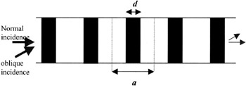
Figure 17.3: Schema of the one-dimensional photonic crystal, consisting of alternating layers of index n 1 and n 2
The optical transmission curves through two identical structures but of different material geometries are shown on the following figures. In Figure 17.4, a normal incidence of the beam with respect to the periodic structure also is considered , the refractive indices of each system being respectively: (1,5/1) and (1,7/1,4). We notice that all the visible region is transmitted and reflect perfectly the signal at 1,55 ¼ m. The transmission can reach in this case ˆ’ 90 dB.
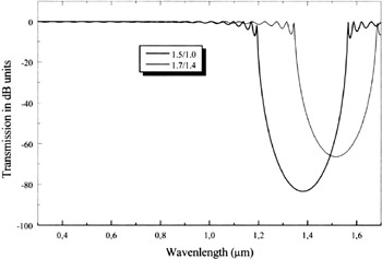
Figure 17.4: Transmission curves versus the incident wavelength of the two different systems n 1 /n 2 : (1,5/1) and (1,7/1,4)
Unfortunately, for this one dimensional structure the answer depends and is strongly affected by the change of the angle of incidence. Indeed, when the angle exceeds 30 ° our structure as illustrated in Figure 17.4 deviates from its principal goal which is reflecting the incident wave at 1.55 ¼ m (see Figure 17.5). Thus, a shift of the photonic band gap to the higher wavelength and a decrease in its magnitude are simultaneously obtained.
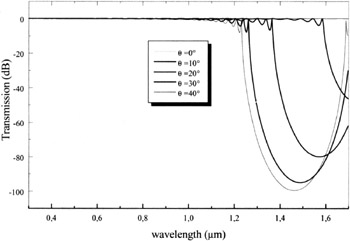
Figure 17.5: Transmission curve versus the incident wavelength for the second system (n 1 /n 2 )= (1,7/1,4) for different angles
For the application aimed in our case, if one limits oneself to an attenuation of the transmitted signal of ˆ’ 40dB, the solution consists in using at least two sets of multilayer systems, which cover higher numerical aperture.
If one requires a rejection rate higher than ˆ’ 40dB, it is necessary either to optimise the multi-layer systems parameters (i.e. the refractive index, the ratio r/a and the lattice constant a) or to consider a photonic crystal of two or three dimensions.
EAN: 2147483647
Pages: 191