17.20 DRAWING SHAPES, TEXT, AND IMAGES IN Qt
|
17.20 DRAWING SHAPES, TEXT, AND IMAGES IN Qt
As mentioned previously, graphics programming deals with rendering geometric shapes, displaying images, playing animation, sketching free-form figures with a mouse pointer, and so on. Central to graphics programming in Qt is the polymorphic behavior of those virtual functions that are automatically invoked in response to certain low-level events. For example, when a QWidget object needs to be drawn on a computer screen, the low-level event QPaintEvent is sent to the widget, where its receipt causes automatic invocation of the paintEvent method. So, as with the paint method for AWT components and the paintComponent method for Swing components, if a programmer extends the QWidget class and supplies an override definition for paintEvent, it's the programmer's definition of paintEvent that will be invoked any time the new widget needs to be drawn. Thus, by incorporating calls to the rendering routines in the override definition of paintEvent, one can display shapes, images, text, and so on, in the new widget.
A typical override definition for paintEvent consists of first constructing a QPainter object and then invoking one of the many methods defined for this class for graphical programming. The QPainter class plays an important role in practically all graphical programming in Qt as it has been provided with a large number of methods whose functionality runs the gamut from rendering geometrical shapes, to displaying images, to drawing text strings, to affecting coordinate transformations, and so on.
Other graphical applications, such as those involving free-form sketching in a QWidget object, depend on the programmer supplying override definitions for virtual event handlers such as mousePressEvent, mouseMoveEvent, and so on, that are automatically invoked upon receipt of low-level mouse events of the type QMouseEvent.
In the rest of this section, we will first show code that renders shapes, images, text, and so on, in a widget via the override definition for the paintEvent method. Next we will show how low-level mouse events can be handled for sketching, and so on.
In the following example, all of the graphics code for the class RenderGraphicsWidget is invoked through the override definition for the paintEvent method in line (M). This method is invoked whenevera RenderGraphicsWidget object is displayed for the first time, or whenever it is resized, or when it is exposed because an overlying widget was moved away. Also, the methods update and repaint defined for the QWidget class can be used to force a paint event and to thus cause paintEvent to be invoked.
Basic to shape rendering in Qt is the specification of the following three items;
-
Coordinate Transformation: A coordinate transformation specifies the location of the origin and the directions of the x and y axes for the purpose of drawing a shape. Ordinarily, if no coordinate transformation is specified, the origin is taken to be the upper left corner of the widget (excluding the space occupied by the title bar and the borders); the x direction is taken to increase to the right; and the y direction is taken to increase downwards.
The default location of the origin and the default directions of the axes can be changed by specifying a 3 × 3 affine matrix:
m11 m12 0 m21 m22 0 dx dy 1
In Qt, this matrix defines an object of type QWMatrix. The elements dx and dy control the translation of the origin; the elements m11 and m22 specify the horizontal and the vertical scaling; the elements m12 and m21 specify horizontal and vertical shear; and, provided certain mathematical conditions are satisfied, the elements m11, m12, m21, m22 together control the rotation.
A QMatrix object may be constructed by directly specifying all the elements, as in
QWmatrix matrix; //(A) matrix.setMatrix(1.0, 0.0, 0.0, 1.0, 0.0, 0.0) //(B)
for specifying what's knows as the identity transformation, which leaves the coordinate frame unchanged. The order of appearance of the arguments in the call to setMatrix is m11, m12, m21, m22, dx, and dy. However, in most situations, it is more convenient to set the coordinate transformation by invoking translate, rotate, scale, and so on, on a QWMatrix object:
QWMatrix matrix; matrix.translate(150, 0); //(C) matrix.rotate((float)3*10); //(D) painter.setWorldMatrix(matrix); //(E)
As one would expect, translate shifts the origin along the x and the y directions by the number of pixels that are supplied to it as arguments. In the code snippet shown, the origin will be shifted by 150 pixels along x and none along y. Similarly, rotate rotates the coordinate frame in a clockwise direction by the number of degrees supplied to it as argument. After a QWMatrix object is given values either directly by invoking setMatrix, or indirectly by the invocations of translate, rotate, and scale as shown, the QPainter object in charge of rendering in the window must be informed of the new coordinate transformation by calling setWorldMatrix, as we do in line (E) above.
After the coordinate frame used by the QPainter object is transformed, any invocations of a "draw" function would be in the new coordinate frame. For example, if we invoke
painter.drawRect(10, 10, 100, 50); //(F)
the first two arguments to drawRect, which stand for the pixel coordinates of the upper left corner of the rectangle, will be interpreted with respect to the new coordinate frame. The next two arguments, for the width and the height of the rectangle, will now be the width along the new x axis and the height along the new y axis.
After one or more transformations, it sometimes becomes necessary to reset the coordinate frame to its default. As we show in line (T) in the example code below, this can be achieved by invoking reset on the QWMatrix object. This can also be achieved by invoking setMatrix with values corresponding to the identity matrix. This latter approach is shown commented out after the line labeled (T).
-
The Fill Pattern: The fill pattern refers to how to display the interior of a shape. The interior of a shape could be rendered with a solid color, or with some sort of shading or hatching, or it could be left blank to show the background pixels. A fill pattern is specified by constructing a QBrush object and then informing the painter of that fact, as in
QBrush b3(Qt::red, Qt::Dense2Pattern); //(G) painter.setBrush(b3); //(H)
This tells the QPainter object, painter, that the brush to use for the interior of a shape is the b3 object. That would cause the interior to be dotted red, the dot density being 20%.[31] Lines (P1) through (P5) of the program below show five different fill pattern specifications.
-
The Border: The border of a shape can be drawn in different styles by invoking setPen on the painter object, as in line (Q) of the program. Ordinarily, a onepixel thick border consisting of a solid line is drawn, but that can be changed by giving appropriate arguments to setPen.
Shown below is a Qt example that renders a sampling of shapes and an image:
//RenderGraphics.cc #include <qwidget.h> #include <qpainter.h> #include <qapplication.h> #include <qpixmap.h> class RenderGraphicsWidget : public QWidget { //(I) public: RenderGraphicsWidget(); //(J) protected: void paintEvent(QPaintEvent *); //(K) }; RenderGraphicsWidget::RenderGraphicsWidget() { //(L) setCaption("Render Graphics with Qt"); setBackgroundColor(white); } void RenderGraphicsWidget::paintEvent(QPaintEvent*) { //(M) QWMatrix matrix; //(N) QPainter painter(this); //(O) QBrush b1(Qt::NoBrush); //(P1) QBrush b2(Qt::magenta); //(P2) QBrush b3(Qt::red, Qt::Dense2Pattern); //(P3) QBrush b4(Qt::blue, Qt::Dense7Pattern); //(P4) QBrush b5(Qt::CrossPattern); //(P5) painter.setPen(Qt::red); //(Q) painter.setBrush(b1); //(R) painter.drawRect(10, 10, 100, 50); //(S) matrix.translate(150, 0); matrix.rotate((float)3*10); painter.setWorldMatrix(matrix); painter.setBrush(b2); painter.drawRoundRect(10, 10, 100, 50, 30, 30); matrix.rotate( − (float)3*10); matrix.translate( − 150, −30); matrix.shear(0.8, 0.2); painter.setWorldMatrix(matrix); painter.setBrush(b3); painter.drawRect(250, 0, 100, 50); matrix.reset(); //(T) // matrix.setMatrix(1.0, 0.0, 0.0, 1.0, 0.0, 0.0); painter.setWorldMatrix(matrix); painter.setBrush(b4); painter.drawRect(10, 200, 100, 50); painter.setBrush(b5); painter.drawEllipse(130, 200, 100, 50); painter.setPen(Qt::NoPen); QPixmap pix("allthatjazz.xpm"); pix.resize(100, 50); painter.drawPixmap(260, 200, pix); int y = 300; painter.setWorldMatrix(matrix); QFont font("Times", 18); painter.setFont(font); QFontMetrics fm = painter.fontMetrics(); y += fm.ascent(); painter.drawText(70, y, "Graphics rendered using QPainter methods"); } int main(int argc, char **argv) { QApplication app(argc, argv); RenderGraphicsWidget drawdemo; drawdemo.setGeometry(200, 200, 450, 400); app.setMainWidget(&drawdemo); drawdemo.show(); return app.exec(); }
This program can be compiled with the following command line
g++ -o RenderGraphics RenderGraphics.cc -I$QTDIR/include \ -L$QTDIR/lib -lqt
The window produced by this program is shown in Figure 17.38.
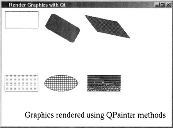
Figure 17.38
Our next example shows how low-level mouse events can be put to use for free-form sketching. An event of type MouseEvent occurs when a button is pressed or released inside a widget or when the mouse cursor is moved. When such an event occurs, the following virtual and protected functions of the QWidget class are authomatically invoked:
mousePressEvent(MouseEvent*) mouseReleaseEvent(MouseEvent*) mouseDoubleClickEvent(MouseEvent*) mouseMoveEvent(MouseEvent*)
By providing override definitions for one or more of these functions in your own extension of the QWidget class you can put the mouse to use for various graphics-related activities-sketching, for example.
In the following program, the user clicks the mouse at different points in a window and, when the user double clicks, the points are joined together by straight lines in the order in which they were clicked, forming a polyline. As the user clicks away, the coordinates of the mouse cursor are retrieved in the mousePressEvent function in line (V) by invoking pos on the MouseEvent object that is the argument of the function. The pos function returns an object of type QPoint, which is basically a pairing of the x and the y coordinates of a point, the coordinates being measured relative to the upper left corner of the widget that receives the mouse event.
When the user double-clicks the mouse, note how we force a paint event by invoking repaint in line (W). The occurrence of this event triggers the automatic invocation of the event handler paintEvent of line (U), which causes the sketch to be displayed.
//Sketch.cc #include <qapplication.h> #include <qpainter.h> #include <qwidget.h> const int MAXPOINTS = 200; class SketchWidget : public QWidget { public: SketchWidget(QWidget *parent=0, const char *name=0); ~SketchWidget(); protected: void paintEvent(QPaintEvent *); void mousePressEvent(QMouseEvent *); void mouseDoubleClickEvent(QMouseEvent*); private: QPoint *points; int count; }; SketchWidget::SketchWidget(QWidget *parent, const char *name) : QWidget(parent, name) { setBackgroundColor(white); count = 0; points = new QPoint[MAXPOINTS]; } SketchWidget::~SketchWidget() { delete[] points; } void SketchWidget::paintEvent(QPaintEvent*) { //(U) QPainter paint(this); for (int i=0; i<count - 2; i++) { paint.drawLine(points[i], points[ i + 1 ]); } } void SketchWidget::mousePressEvent(QMouseEvent* mouse) { //(V) points[count++] = mouse->pos(); } void SketchWidget::mouseDoubleClickEvent(QMouseEvent* mouse) { points[count++] = mouse->pos(); repaint(); //(W) } int main(int argc, char* argv[]) { QApplication app(argc, argv); SketchWidget* sketchWidget = new SketchWidget(); sketchWidget->setGeometry(200, 200, 200, 200); sketchWidget->show(); app.setMainWidget(sketchWidget); return app.exec(); }
This program can be compiled with the following command line
g++ -o Sketch Sketch.cc -I$QTDIR/include -L$QTDIR/lib -lqt
Figure 17.39 shows a sample sketch in a window created by this program.
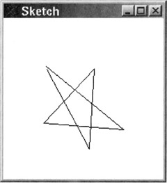
Figure 17.39
[31]The class Qt serves as a repository of identifiers that are needed on a global basis by the Qt toolkit. For example, via the header file namespace.h, the class Qt makes available the identifiers black, white, darkGray, gray, lightGray, red, green, blue, cyan, magenta, yellow, darkRed, darkGreen, darkBlue, darkCyan, darkMagenta, darkYellow, and so on, for convenient-to-use color names. Of course, one can also specify an arbitrary color by constructing a QColor object. The identifiers made available in a similar manner for brush styles include NoBrush, Dense1Pattern, Dense2Pattern, …, Dense7Pattern, Crosspattern, and so on, where the middle numeral in the dense pattern name refers to the fill density of the dots. For specifying the border of a shape, the class Qt makes available the identifiers NoPen, SolidLine, DashLine, DotLine, DashDotLine, and so on.
|
EAN: 2147483647
Pages: 273