Using Switching Technologies
Switching technologies are crucial to the new network design. Because the prices on layer 2 switching have been dropping dramatically, it is easier to justify the cost of buying switches for your entire network. This doesn’t mean that every business can afford switch ports for all users, but it does allow for a cost-effective upgrade solution when the time comes.
To understand switching technologies and how routers and switches work together, you must understand the Open Systems Interconnection (OSI) model. This section will give you a general overview of the OSI model and the devices that are specified at each layer.
| Note | You’ll need a basic understanding of the OSI model to fully understand discussions in which it is included throughout the rest of this book. For more detailed information about the OSI model, please see CCNA: Cisco Certified Network Associate Study Guide, 4th edition, by Todd Lammle (Sybex, 2003). |
Open Systems Interconnection (OSI) Model
As you probably already know, the Open Systems Interconnection (OSI) model has seven layers, each of which specifies functions that enable data to be transmitted from host to host on an internetwork. Figure 1.4 shows the OSI model and the functions of each layer.

Figure 1.4: The OSI model and the layer functions
The OSI model is the cornerstone for application developers to write and create networked applications that run on an internetwork. What is important to network engineers and technicians is the encapsulation of data as it is transmitted on a network.
Data Encapsulation
Data encapsulation is the process by which the information in a protocol is wrapped, or contained, in the data section of another protocol. In the OSI reference model, each layer encapsulates the layer immediately above it as the data flows down the protocol stack.
The logical communication that happens at each layer of the OSI reference model doesn’t involve many physical connections, because the information each protocol needs to send is encapsulated in the layer of protocol information beneath it. This encapsulation produces a set of data called a packet (see Figure 1.5).
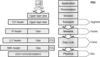
Figure 1.5: Data encapsulation at each layer of the OSI reference model
Looking at Figure 1.5, you can follow the data down through the OSI reference model as it’s encapsulated at each layer. Cisco courses typically focus only on layers 2 through 4.
Each layer communicates only with its peer layer on the receiving host, and they exchange Protocol Data Units (PDUs). The PDUs are attached to the data at each layer as it traverses down the model and is read only by its peer on the receiving side. Each layer has a specific name for the PDU, as shown in Table 1.1.
| OSI Layer | Name of Protocol Data Units (PDUs) |
|---|---|
| Transport | Segments |
| Network | Packets |
| Data Link | Frames |
| Physical | Bits |
Starting at the Application layer, data is converted for transmission on the network, and then encapsulated in Presentation layer information. When the Presentation layer receives this information, it looks like generic data. The Presentation layer hands the data to the Session layer, which is responsible for synchronizing the session with the destination host.
The Session layer then passes this data to the Transport layer, which transports the data from the source host to the destination host in a reliable fashion. But before this happens, the Network layer adds routing information to the packet. It then passes the packet on to the Data Link layer for framing and for connection to the Physical layer. The Physical layer sends the data as 1s and 0s to the destination host. Finally, when the destination host receives the 1s and 0s, the data passes back up through the model, one layer at a time. The data is de-encapsulated at each of the OSI model’s peer layers.
At a transmitting device, the data encapsulation method is as follows:
-
User information is converted to data for transmission on the network.
-
Data is converted to segments at the Transport layer, and any reliability parameters required are set up.
-
Segments are converted to packets or datagrams at the Network layer, and routing information is added to the PDU.
-
Packets or datagrams are converted to frames at the Data Link layer, and hardware addresses are used to communicate with local hosts on the network medium.
-
Frames are converted to bits, and 1s and 0s are encoded within the digital signal.
Now that you have a sense of the OSI model and how routers and switches work together, it is time to turn our attention to the specifics of each layer of switching technology.
Layer 2 Switching
Layer 2 switching is hardware based, which means it uses the Media Access Control (MAC) address from the host’s network interface cards (NICs) to filter the network. Switches use application-specific integrated circuits (ASICs) to build and maintain filter tables. It is okay to think of a layer 2 switch as a multiport bridge.
Layer 2 switching provides the following:
-
Hardware-based bridging (MAC)
-
Wire speed
-
High speed
-
Low latency
-
Low cost
Layer 2 switching is so efficient because there is no modification to the data packet, only to the frame encapsulation of the packet, and only when the data packet is passing through dissimilar media (such as from Ethernet to FDDI).
Use layer 2 switching for workgroup connectivity and network segmentation (breaking up collision domains). This enables you to create a flatter network design and one with more network segments than traditional 10BaseT shared networks.
Layer 2 switching has helped develop new components in the network infrastructure:
Server farms Servers are no longer distributed to physical locations because virtual LANs can be used to create broadcast domains in a switched internetwork. This means that all servers can be placed in a central location, yet a certain server can still be part of a workgroup in a remote branch, for example.
Intranets These enable organization-wide client/server communications based on a web technology.
These new technologies are enabling more data to flow off local subnets and onto a routed network, where a router’s performance can become the bottleneck.
Limitations of Layer 2 Switching
Layer 2 switches have the same limitations as bridge networks. Remember that bridges are good if you design the network by the 80/20 rule: users spend 80 percent of their time on their local segment.
Bridged networks break up collision domains, but the network is still one large broadcast domain. Similarly, layer 2 switches (bridges) can not break up broadcast domains, which can cause performance issues and limits the size of your network. Broadcasts and multicasts, along with the slow convergence of spanning tree, can cause major problems as the network grows. Because of these problems, layer 2 switches can not completely replace routers in the internetwork.
Routing
We want to explain how routing works and how routers work in an internetwork before discussing layer 3 switching next. Routers and layer 3 switches are similar in concept but not design. In this section, we’ll discuss routers and what they provide in an internetwork today.
Routers break up collision domains as bridges do. In addition, routers also break up broadcast/ multicast domains.
The benefits of routing include:
-
Breakup of broadcast domains
-
Multicast control
-
Optimal path determination
-
Traffic management
-
Logical (layer 3) addressing
-
Security
Routers provide optimal path determination because the router examines each and every packet that enters an interface and improves network segmentation by forwarding data packets to only a known destination network. Routers are not interested in hosts, only networks. If a router does not know about a remote network to which a packet is destined, it will just drop the packet and not forward it. Because of this packet examination, traffic management is obtained.
The Network layer of the OSI model defines a virtual—or logical—network address. Hosts and routers use these addresses to send information from host to host within an internetwork. Every network interface must have a logical address, typically an IP address.
Security can be obtained by a router reading the packet header information and reading filters defined by the network administrator (access lists).
Layer 3 Switching
The only difference between a layer 3 switch and a router is the way the administrator creates the physical implementation. Also, traditional routers use microprocessors to make forwarding decisions, and the switch performs only hardware-based packet switching. However, some traditional routers can have other hardware functions as well in some of the higher-end models. Layer 3 switches can be placed anywhere in the network because they handle high-performance LAN traffic and can cost-effectively replace routers.
Layer 3 switching is all hardware-based packet forwarding, and all packet forwarding is handled by hardware ASICs. Layer 3 switches really are no different functionally from a traditional router and perform the same functions, which are listed here:
-
Determine paths based on logical addressing
-
Run layer 3 checksums (on header only)
-
Use Time to Live (TTL)
-
Process and respond to any option information
-
Can update Simple Network Management Protocol (SNMP) managers with Management Information Base (MIB) information
-
Provide security
The benefits of layer 3 switching include the following:
-
Hardware-based packet forwarding
-
High-performance packet switching
-
High-speed scalability
-
Low latency
-
Lower per-port cost
-
Flow accounting
-
Security
-
Quality of service (QoS)
Layer 4 Switching
Layer 4 switching is considered a hardware-based layer 3 switching technology that can also consider the application used (for example, Telnet or FTP). Layer 4 switching provides additional routing above layer 3 by using the port numbers found in the Transport-layer header to make routing decisions. These port numbers are found in Request for Comments (RFC) 1700 and reference the upper-layer protocol, program, or application.
Layer 4 information has been used to help make routing decisions for quite a while. For example, extended access lists can filter packets based on layer 4 port numbers. Another example is accounting information gathered by NetFlow switching in Cisco’s higher-end routers.
The largest benefit of layer 4 switching is that the network administrator can configure a layer 4 switch to prioritize data traffic by application, which means a QoS can be defined for each user. For example, a number of users can be defined as a Video group and be assigned more priority, or bandwidth, based on the need for videoconferencing.
However, because users can be part of many groups and run many applications, the layer 4 switches must be able to provide a huge filter table or response time would suffer. This filter table must be much larger than any layer 2 or 3 switch. A layer 2 switch might have a filter table only as large as the number of users connected to the network, maybe even smaller if some hubs are used within the switched fabric. However, a layer 4 switch might have five or six entries for each and every device connected to the network! If the layer 4 switch does not have a filter table that includes all the information, the switch will not be able to produce wire-speed results.
Multi-Layer Switching (MLS)
Multi-layer switching combines layer 2, 3, and 4 switching technologies and provides high- speed scalability with low latency. It accomplishes this combination of high-speed scalability with low latency by using huge filter tables based on the criteria designed by the network administrator.
Multi-layer switching can move traffic at wire speed and also provide layer 3 routing, which can remove the bottleneck from the network routers. This technology is based on the concept of route once, switch many.
Multi-layer switching can make routing/switching decisions based on the following:
-
MAC source/destination address in a Data Link frame
-
IP source/destination address in the Network-layer header
-
Protocol field in the Network-layer header
-
Port source/destination numbers in the Transport-layer header
There is no performance difference between a layer 3 and a layer 4 switch because the routing/switching is all hardware based.
| Note | MLS will be discussed in more detail in Chapter 7, “Multi-Layer Switching.” |
It is important that you have an understanding of the different OSI layers and what they provide before continuing on to the Cisco three-layer hierarchical model.
EAN: 2147483647
Pages: 174