Hands-On Lab
In this lab, you will configure two HSRP groups, with one of the routers acting as the active gateway for one VLAN and vice versa. Refer to Figure 9.12 for the topology of this lab. This lab will use the two routers shown to configure HSRP in such a way as to provide load sharing to the Internet for attached hosts.
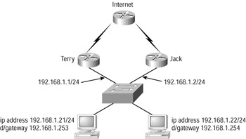
Figure 9.12: Network diagram for the hands-on lab
First, make sure the configurations of your routers and switches are fully deleted. Then configure the switch with the basic hostname and password details as covered in Chapter 2, 'Connecting the Switch Block.' Create and name one VLAN, and assign ports to the VLAN as shown in the diagram. These configuration commands were covered in Chapter 3. On the routers, set the hostname and passwords also, using standard IOS commands.
-
Now set the IP addresses on the two PCs to the values in the diagram, and remember to set the default gateways to the values shown as the correct standby group IP address of the HSRP router pair. Note that the two PCs, although belonging to the same subnet, use different default gateway addresses.
-
Configure the two HSRP routers with individual IP addresses on the Ethernet interfaces. Test that the Ethernet is working properly by pinging between routers. Here are the commands:
Terry#conf t Terry(config)#int e0 Terry(config-if)#ip address 192.168.1.1 255.255.255.0 Jack#conf t Jack(config)#int e0 Jack(config-if)#ip address 192.168.1.2 255.255.255.0
-
Configure the two HSRP routers with individual IP addresses on the serial interfaces. As you are using a null-modem cable, remember to configure a clock on the DCE end of the cable, and to start up the interfaces. Here are the commands:
Terry1#conf t Terry1(config)#int s0 Terry1(config-if)#ip address 192.168.2.1 255.255.255.0 Terry1(config-if)#clock rate 64000 Terry1(config-if)#no shutdown Terry1(config-if)#exit Terry1(config)#router rip Terry1(config-router)#network 192.168.1.0 Terry1(config-router)#network 192.168.2.0 Terry1(config)#^c Jack#conf t Jack(config)#int s0 Jack(config-if)#ip address 192.168.3.1 255.255.255.0 Jack(config-if)#clock rate 64000 Jack(config-if)#no shutdown Jack(config-if)#exit Jack(config)#router rip Jack(config-router)#network 192.168.1.0 Jack(config-router)#network 192.168.3.0 Jack(config)#^c
-
Configure the Internet router to connect to the two HSRP routers over the serial links. Here are the commands:
Internet#conf t Internet(config)#int s0 Internet(config-if)#ip address 192.168.2.2 255.255.255.0 Internet(config)#no shutdown Internet(config)#int s1 Internet(config-if)# ip address 192.168.3.2 255.255.255.0 Internet(config-if)#no shutdown Internet(config)#^c
-
In order to test the path that packets take through the network, we need to configure a target IP address. We will do this by configuring interface loopback 0 on the Internet router as follows:
Internet#conf t Internet(config)# int lo0 Internet(config-if)#ip address 192.168.4.1 255.255.255.0
-
We now need to build a simple routing table, just to allow us to test the configuration. Use RIP v1, and remember to include the locally connected networks to each router in the configuration. For example:
Internet#conf t Internet(config)#router rip Internet(config-router)#network 192.168.2.0 Internet(config-router)#network 192.168.3.0 Internet(config-router)#network 192.168.4.0 Internet(config)#^c
-
Now we need to build the HSRP configuration proper. This configuration is carried out only on the two HSRP routers. The router called Terry will be the active router for group 1, and the router Jack will be the active router for group 2. Each router will act as the standby router for the other HSRP group.
Terry(config)#int e0 Terry(config-if)#standby 1 ip 192.168.1.253 Terry(config-if)#standby 1 priority 105 Terry(config-if)#standby 1 preempt Terry(config-if)#standby 2 ip 192.168.1.254 Terry(config-if)#standby 2 preempt Jack(config)#int e0 Jack(config-if)#standby 1 ip 192.168.1.253 Jack(config-if)#standby 1 preempt Jack(config-if)#standby 2 ip 192.168.1.254 Jack(config-if)#standby 2 preempt Jack(config-if)#standby 2 priority 105
-
We must test this configuration. If you have a traceroute application running on your PC, you can easily trace the route a packet takes. If not, then you must do the following:
Open a command window on the PC, and start a continuous ping to the loopback address of the Internet router. Once the ping starts to be returned, open the console window on both routers and enter the command debug ip packet detail.
This command will show which of the two routers is carrying the IP traffic from the ping. Testing using pings from both PCs should show that traffic from one travels via the router Terry and the other transmits via the router Jack.
-
The last part of the lab is to see what happens when a failure occurs. First, we need to carry out some additional configuration.
We have already set the priority for the active router to 105 (remember that the default is 100). Now we need to make sure that when the serial link fails, the active router becomes standby. This involves tracking the serial interface, as shown in the following commands:
Terry(config)#int e0 Terry(config-if)#standby 1 track serial 0 Terry(config)#^c Jack(config)#int e0 Jack(config-if)#standby 2 track serial 0 Jack(config)#^c
-
To test the tracking configuration, start a continuous ping as in step 8, and determine the path taken.
Remove the serial cable carrying the ping traffic and see the interruption in the returned pings to the PC. After a few seconds, the pings should resume, demonstrating that the second router has become active.
For a different view of the same event, enter the command debug standby, and restore the serial connection. You should see the hello packets change to include the higher value once the serial link becomes active, and the standby router will preempt. This should cause no loss to returned pings at all.
EAN: 2147483647
Pages: 174