| A Web site's architecture relates to how information is presented to an audience. Creating a good site architecture will save you a lot of "Oops, I forgot that!" curses while building the site. Although the purpose of this chapter is not to delve into the arcane science of site design, it does cover some basic concepts as you learn how to use FreeHand to maximize your designs. Create a Site Map with the Connector Tool First things first. It's helpful to create a preliminary site map to minimize the chances for creating a confusing navigation system. Although this can be accomplished in Dreamweaver, the site map that is created is typically not suitable for presentations to clients or anyone else that will need to see and approve your concept (Figure 30.1). This is where FreeHand comes into play. Figure 30.1. Dreamweaver's site map is great for the designer, but is not the best way to show a client a site map. 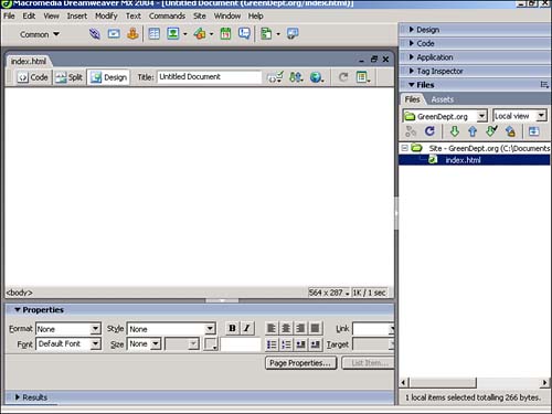
For our purposes, we will create a site map for greendept.org, a case study that is being used elsewhere in this book. This site will cater to people who want to find information on anything and everything ecological ”environmentally friendly products, services, and events. Based on the information provided by the client, we know they want to have the following categories showcased on the site: -
Home -
Search -
Log-In -
Events -
About Us -
Contact Us Create a new document (File, New). Before you start drawing, go ahead and save the file (File, Save) and name it "sitemap." Start your site map by rendering the top level of the site, which is usually several pages, and includes the home page. Use the Rectangle tool to draw a page icon. Select a fill and stroke. Next, select the Text tool and create a label, "Home," as shown in Figure 30.2. Figure 30.2. Create a home page icon for the site map by using the Rectangle tool. 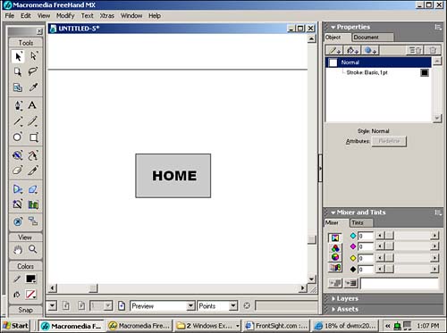
To create page icons for these navigation elements, simply duplicate the Home page icon. Use the Select tool to draw a marquee around the Home page icon to include the rectangle and text block. Copy these objects by using the Copy command (Edit, Copy) and then Paste (Edit, Paste). Use the Select tool to reposition the duplicate icon (Figure 30.3). Figure 30.3. Duplicate the Home icon by using the Copy command. 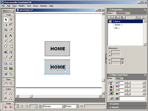
Then use the Type tool to rename the label from "Home" to "Search". Rinse and repeat to create page icons for the remaining main navigation elements, as shown in Figure 30.4. Figure 30.4. Duplicate the original "Home" page icon and edit the text label until you have your top navigation level represented. 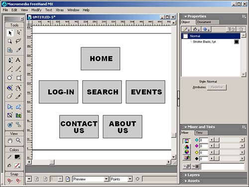
Use the Connector tool to indicate links between the page icons. The Connector tool creates lines that will automatically stay connected to objects. In this case, the objects are the page icons. The beauty of using the Connector tool at this stage of the site design is that you don't have to redraw connections (links) every time there is a change to the structure. This is what makes the Connector tool an ideal site mapping device during the fluid conceptualization process. To connect the page icons, select the Connector tool from the panel. Position your cursor near the bottom of the "Home" page icon. A small circle appears, indicating that you can begin to draw your connector line. Drag toward the top of the Search page icon. Release the mouse when you see the small circle appear on the cursor once again. The connector line automatically appears, as shown in Figure 30.5. You've just created a visual "link" between your pages. Figure 30.5. Use the Connector tool to create a dynamic connection between your page icons. 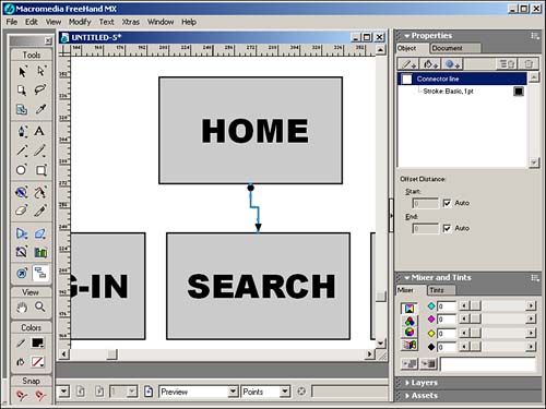
After you've repeated the process and created links from your Home page icon to all other top-level page icons (Search, Log-In, Events, About Us, Contact Us), you should have a page that looks something like Figure 30.6. Figure 30.6. The "connected" site map. 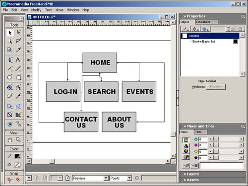
Here's where the magic happens. Go ahead and reposition your page icons and watch the connector lines magically follow your every move. Set up an arrangement that is visually appealing to you (Figure 30.7). Figure 30.7. When you reposition objects that are connected, the connector lines are automatically redrawn. 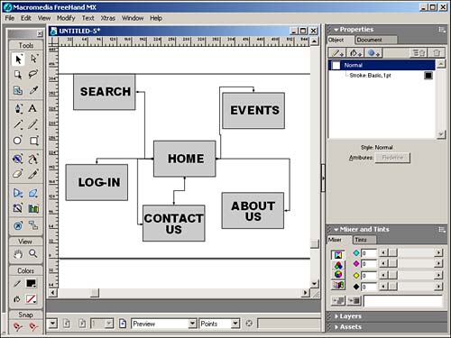
If you don't like the direction your arrows are going between objects, you can reverse the direction. Select the connector line with either of the selection tools or the Connector tool. Use the Reverse Direction command (Modify, Alter Path, Reverse Direction). The arrowhead and the default "ball" are reversed . Because you are working in the wonderful world of the Web, however, you won't be creating one-way links. Your pages should show that that the links work both ways. This is best accomplished by using an arrowhead at each end of the connector line. Select any existing connector line. In the Objects panel, select Connector Line to view the line's properties. Using either drop-down menu, you can select an arrowhead for either end of the connector line (Figure 30.8). Figure 30.8. Use the Objects panel to change the appearance of your connector lines. 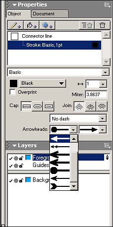
The second level in a site architecture contains the pages you navigate to by going "down from" the top-level pages. In this example, a top-level page called Events would have second-level pages that go into more detail about each of the events, as well as provide links to a calendar of future events, as shown in Figure 30.9. Figure 30.9. Use your second-level pages to show more detail about subtopic content. 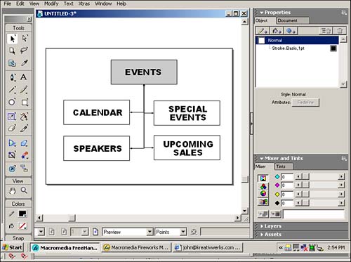
Having a second-level navigation scheme is important so you don't have to go up to the top level just to see the other choices in the same second level you're in. |