10.1 Visualizing Structures
| The structural view of a system focuses on the static parts of that system. This view examines how the elements in the system are constructed . It examines its attributes, properties, and operations along with its organization, composition, and relationship with other elements in the system. The diagraming techniques discussed in this section are the ones used to model:
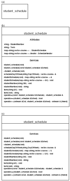
The elements documented can be conceptual or physical. 10.1.1 Classes and ObjectsA class is a model of a construct with its attributes and behaviors. It is a description of a set of things or objects that share the same attributes. A class is the basic component of any object-oriented system. Classes can be used to represent real-world, conceptual, hardware, and software constructs. A class diagram is used to represent the classes, the objects, and the relationships that exist between them within your concurrent and/or distributed system. The class diagram is used to show the attributes and the services a class provides and the restrictions that apply to the manner in which these classes/objects are connected. The UML provides a graphical representation of a class. The simplest representation of a class is a rectangular box that contains the name of the class. The name alone is the simple name . The class diagram can also show the attributes and services provided to the user of the class. To include attributes and services, a rectangle is drawn displaying three horizontal compartments. The top compartment displays the simple name of the class, the middle compartment displays the attributes, and the bottom compartment displays the services. The attributes and services compartments can be labeled "attributes" and "services," respectively, in order to identify each compartment. Besides the name of the class, if the attributes or services are to be shown, then the other compartment is displayed as empty. Figure 10-1 shows the various ways a class can be represented. Figure 10-1. The various ways to represent a class. In Figure 10-1, the class student_schedule is represented. Figure 10-1(a) shows the class in its simplest representation, (b) shows the class name and its attributes and services, and (c) shows the class name and its services. The compartment that contains the attributes is empty in order to communicate that the class has attributes but they are not shown. An additional compartment can be used to describe the responsibility of the class . This compartment appears under the services compartment and can be omitted. The responsibility of the class is what the class will perform. It is displayed as contractual statements. These responsibilities are transformed into services and attributes. Attributes are transformed into datatypes and data structures and services are transformed into methods . This compartment can be labeled "responsibilities" . The responsibilities of the student_schedule class can be stated as: "returns the schedule for a student for any day of the week, the student number, the year, and term of the stored schedule." The responsibilities of the class are displayed as text in its compartment where each responsibility is listed as a short statement or paragraph. The class diagram can show an object, an instance of a class. Like a class, the simplest representation of an object is a rectangle that contains the name of the object underlined . This is called a named instance of a class. A named instance of a class can be shown with or without its class name:
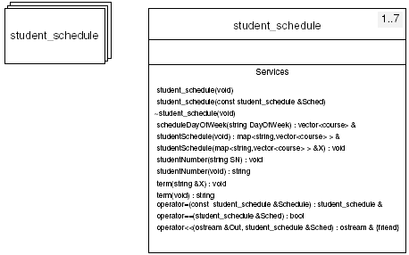
Since the actual name of the object may be known only to the program that declares it, you may want to represent anonymous instances of classes in your system documentation. You can label an object as anonymous in this way: :student_schedule This type of labeling may be convenient where there are several instances of a class in your system. Several instances of a class can be represented in two ways: as objects and as classes. The number of instances a class may have is called multiplicity . The number of instances of a class can be noted in a class diagram. A class may have zero to an infinite number of instances. A class with zero instances is a pure abstract class . It cannot have any objects explicitly declared of its type. The number of instances may have an upper or lower bound, which may also be expressed in the diagram of a class. Figure 10-2 shows how several instances of a class can be represented in a class diagram as objects or with multiplicity notation. Figure 10-2. Mutiple instances of a class represented graphically and using multiplicity notation. In Figure 10-2, the multiplicity of the student_schedule class is 1..7 , meaning the least number of student schedules in our system is 1 and the most that can exist is 7. Here are more examples of multiplicity notation and their meaning:
Of course, an infinite number of instances will be limited by internal memory or external storage. 10.1.1.1 Displaying Specifics about Attributes and ServicesThe class diagram can specify more details about the attributes and services of the class. The attributes compartment can specify the datatype and/or default value (if there is one) for classes and values of attributes for objects. For example, the datatypes for the attributes of the student_schedule class can be displayed: StudentNumber : string Term : string StudentSchedule : map <string,vector<course> > ScheduleIterator : map <string,vector<course> >::iterator For the mySchedule object, these attributes can take on values: StudentNumber : string = "102933" Term : string = "Spring" Methods can be shown with parameters and return type: studentSchedule(&X : map <string,vector<course> >) : void studentNumber() : string The studentSchedule() function accepts the courses of the student. course is a class that models a single course. The courses for each day of the week are stored in a vector . The map container maps a string (day of the week) with the vector of courses for that particular day. The studentSchedule() function returns void where the studentNumber() function returns a string . The properties of attributes and methods can be displayed in the class diagram. Properties help describe how an attribute or operation can be used. Property labels can be used to describe attributes that are constant or modifiable. There are three properties used to describe attributes: changeable , addOnly , and frozen . Table 10-1 lists these properties with a brief description. There are four properties used to define methods: isQuery , sequential , guarded , and concurrent . They are also listed in Table 10-1. sequential , guarded , and concurrent properties are concerned with the concurrency of a method. The sequential property describes a concurrent operation where synchronization is the responsibility of the callers of the operation. These operations do not guarantee the integrity of the object. The guarded property describes a concurrent operation where synchronization is already built in. guarded operations mean callers invoke the operation one at a time. The concurrent property describes an operation that permits simultaneous use. The guarded and concurrent operations guarantee the integrity of the object. Guaranteeing the integrity of an object is applicable to operations that change the state of the object. Table 10-1. Properties for Attributes and Operations
guarded and concurrent properties for methods can be used to reflect the PRAM (Parallel Random-Access Machine) model. If a method is reading and/or writing memory that is accessible to another method that is also reading and/or writing that same memory, then that method can be described as a PRAM algorithm. The properties can be appropriately used. For example:
The student_schedule class can further describe how its attributes and services can be used by using property labels: attributes StudentNumber : string {frozen} Term : string {changeable} StudentSchedule : map <string,vector<course> > {changeable} operations scheduleDayOfWeek(&X : vector<course>, Day : string) : void {guarded} studentNumber() : string {isQuery, concurrent} StudentNumber is a string constant. Once an object assigns a value, it cannot be changed. If the student_schedule object is used for the same student but for different terms, then Term and StudentSchedule would be modifiable attributes. The scheduleDayOfWeek() operation accepts a vector of courses for a particular day of the week stored in the string Day . This operation is guarded . It inserts a student schedule for a particular day of the week into the map object StudentSchedule , changing the state of the object. Synchronization is built into the object by using mutexes . The studentNumber() operation has two properties: isQuery and concurrent . It returns the constant StudentNumber and is safe for simultaneous access. Calling this method does not change the state of the object thus using the isQuery property. Another important property that can be shown is the visibility of attributes and operations. A visibility property describes who can access the attribute or invoke the operation. This property uses a character or symbol to represent the level of visibility. Visibility maps to the access specifiers of C++:
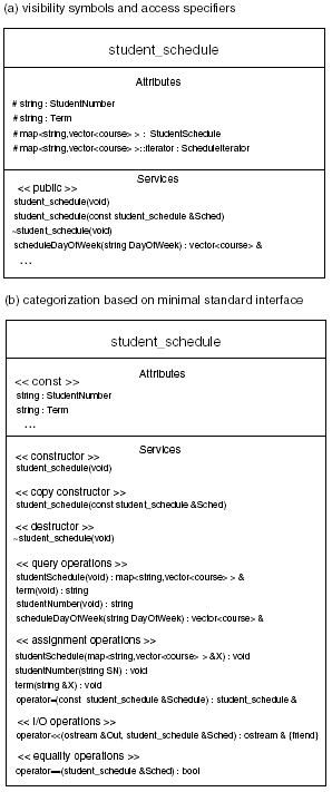
The symbol is prepended to the service, method, or attribute name. 10.1.1.2 Ordering the Attributes and ServicesIt may be best when representing a class with many attributes and operations to organize them within their compartments. Order helps to identify and navigate through the attributes and operations. The organization can be alphabetical, by access, or by category. Alphabetical order is not helpful in identifying what attributes or operations can be called (if the documentation is targeted to users of the system) or which of them are not defined (if documentation is used in the development process). Ordering by access is very useful. It communicates to the user which attributes and operations are publicly accessible. Knowing which members are protected will assist users who need to extend or specialize the class through inheritance. This can be done by using the visibility symbols, + , - , and # , or by using the C++ access specifiers, protected , public , and private . There are several ways to categorize the attributes and operations. The minimal standard interface defines categories for operations that in turn define attributes that support these operations. The minimal standard interface is based on the concept that all classes should define certain operations and services in order for a class to be useful. These operations are:
These can be used as categories to classify the operations of a class. Other categories can be used to help organize attributes and operations: attributes static const operations virtual pure virtual friend These categories should be used based upon what best describes the services offered by the class. The category name is embraced in left and right double angle brackets, ( <<...>> ). Figure 10-3 shows the two ways attributes and operations can be organized for the student_schedule class: (a) using the visibility symbols, access specifiers, and (b) using categorization based on the minimal standard interface. Figure 10-3. Two ways attributes and services can be organized in a class diagram. 10.1.1.3 Template ClassesA template class is a mechanism that allows a type to be a parameter in the definition of the class. The template defines services that manipulate whatever datatype that is passed to it. The parameterized class is created in C++ by using the template keyword: template <class Type > classname {...}; Type parameter represents any type passed to the template. Type can be a built-in datatype or a user-defined class. When Type is declared, the template is bound by the element passed to it as the parameterized type. For example, the student_schedule class has a map container that contains vector s of course objects for each day of the week. Both the map and the vector are template classes: map <string,vector<course> > StudentSchedule; The map container has string as a key and vector as the value. The vector container contains a user-defined course object. The map container can map any datatype to any other datatype and vector containers can contain any datatype:
Template classes are also represented as rectangular boxes. The parameterized type is represented as a dashed box displayed in the upper right-hand corner. The template class can be unbound or bound. When representing an unbound template class, the dashed box displays a capital T to represent the unbound parameterized type. There are two ways to represent a bound template class. One approach is to use the class symbol containing the C++ syntax for declaring and binding a template class: vector <string> This is called implicit binding . Another approach uses a dependency stereotype, bind . The stereotype specifies the source instantiating the template class by using the actual parameterized type. This is called explicit binding . The template object is the instantiation of the template class. It has a dependency relationship with the template class. The stereotype specifies the name of the parameter types. Inside the dashed box, datatypes are displayed. The template object can also be considered as a refinement of the template class. Refinement is a general term to indicate a greater level of detail of something that already exists. The stereotype indicator <<bind>> refines the template class by instantiating the parameterized type. Figure 10-4 depicts the ways a template class can be represented, unbound and bound, for a map container. Figure 10-4. The ways to represent a bound and unbound template class. 10.1.2 The Relationship between Classes and ObjectsThe UML defines three types of relationships between classes:
Dependency defines a relationship between two classes. When one class depends on another class, this means a change to the independent class may affect the dependent class. Generalization is a relationship between a general construct and a more specific type of that construct. The general construct is the parent or superclass and the more specific construct is the child or subclass . The child inherits the properties, attributes, and operations of the parent and may define other attributes and operations of its own. The child is derived from the parent and can be used as a substitute for the parent class. A class that has no parent is called the root or base class. Association is a structural relationship that specifies that objects of one type are connected to objects of another type. Associations between objects are bidirectional. For example, if object 1 is associated with object 2, then object 2 is associated with object 1. An association between two elements (classes, etc.) is called a binary association . An association between n elements is called n-ary association. Table 10-2. Stereotypes That Can Be Applied to Dependencies
Dependency, generalization, and association are actually classifications of relationships. There are many types of dependencies, generalizations, and associations that exist and can be defined. Each relationship classification has its own symbol of representation. That symbol is a solid or dashed line segment between the elements and may be accompanied with some type of arrowhead . To further define that relationship to a specific type, stereotypes or adornments are used in conjunction with the line segment. Stereotypes are labels used to further describe a UML element. It is rendered as a name enclosed by guillemets and placed above or next to the element. For example: <<bind>> was placed next to the arrow, which depicts dependency when describing the template object in Figure 10-4. Adornments are textual or graphical items added to an element's basic representation and are used to document details about that element's specifications. For example, an association is depicted as a solid line between elements. Aggregation is a type of association that expresses a "whole “part" relationship. To depict aggregation, a hollow diamond adorns the solid line at the whole end. Dependency is rendered as a dashed directed line (has a arrow) pointing to the construct being depended on. Use a dependency relationship when one construct uses another. Generalization is rendered as a solid directed line with a large open arrowhead pointing to the parent or superclass. Use a generalization relationship when one construct is derived from another construct. Association is rendered as a solid line connecting the same or different constructs. Use an association relationship when one construct is structurally related to another. Table 10-2 lists some of the stereotypes and constraints that can be applied to dependencies. These stereotypes are used to show dependencies between classes, interactive objects, states, and packages. Tables 10-3 and 10-4 list the stereotypes and constraints that can be applied to generalizations and associations. If any of the stereotypes use graphical adornments, they are shown. Table 10-3. Stereotypes and Constraints That Can Be Applied to Generalizations
Table 10-4. Stereotypes, Constraints, and Adornments That Can Be Applied to Associations
Associations have another level of detail that can be applied to a general association or stereotype listed in Table 10-4:
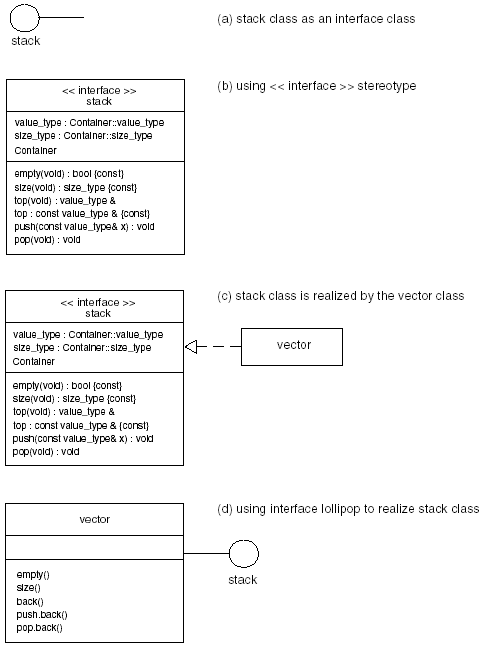
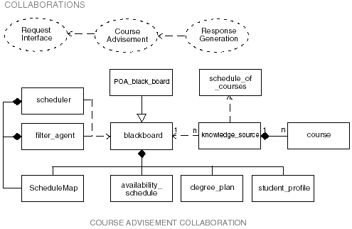
10.1.2.1 Interface ClassesAn interface class is used to modify the interface of another class or set of classes. The modification makes the class easier to use, more functional, safer, or semantically correct. An example of an interface class are the container adaptors that are part of the Standard Template Library. The adaptors provide a new public interface for the deque , vector , and list containers. Example 10.1 shows the stack class. It is used as an interface class to modify a vector class. Example 10.1 Using the stack class as an interface class. template < class Container > class stack{ //... public: typedef Container::value_type value_type; typedef Container::size_type size_type; protected: Container c; public: bool empty(void) const {return c.empty();} size_type size(void) const {return c.size(); } value_type& top(void) {return c.back(); } const value_type& top const {return c.back(); } void push(const value_type& x) {c.push.back(x); } void pop(void) {c.pop.back(); } }; The stack is declared by specifying the Container type: stack < vector< T> > Stack; In this case, the Container is a vector but any container that defines these operations: empty() size() back() push.back() pop.back() can be used as the implementation class for the stack interface class. The stack class supplies the semantically correct interface traditionally accepted for stacks. There are multiple ways to depict an interface. A circle with the name of the interface class outside the circle is one way to represent an interface class. This is depicted in Figure 10-5(a), showing the stack as an interface class. The class symbol can also be used to show the operations of the stack class, Figure 10-5(b). Here the stereotype indicator <<interface>> is displayed above the name of the class to denote that this is an interface class. The letter I can be prepended to the name of the interface class and all of its operations to further distinguish it from other classes. Figure 10-5. Ways to represent an interface class. Realization can be used to show the relationship between the stack and the vector class. Realization is a semantic relationship between classes in which one specifies a contract (interface class) and the other class carries it out (implementation class). In our example, the stack class specifies the contract and the vector class carries it out. A realization relationship is depicted as a dashed line between the two classes with a large open arrowhead pointing to the interface class or the class that specifies the contract, which is depicted in Figure 10-5(c). It is read "The stack class is realized by the vector class." The relationship between the interface class and its implementer can also be depicted with the interface lollipop notation, as shown in Figure 10-5(d). The stack class can be the interface to or realized by a vector , list , or deque . 10.1.3 The Organization of Interactive ObjectsAs you can see, classes and interfaces can be used as building blocks to create more complex classes and interfaces. In a distributed or parallel system, there may be many large and complex structures collaborating with other structures, thus creating a society of classes and interfaces working together to accomplish the goals of the system. In the UML, this is called a collaboration. These building blocks can include both the structural and behavioral elements of the system. A particular task requested by a user may involve many objects working together to accomplish that task. Those same objects working with other elements are used to accomplish other tasks . This collection of elements, together with their interactions, form a collaboration . The collaboration has two parts: a structural part, which focuses on the way the collaborating elements are organized and constructed, and a behavioral part , which focuses on the interaction between the elements. This will be discussed in the next section. A collaboration is depicted as an ellipse with dashed lines containing the name of the collaboration. A collaboration name is unique. It is a noun or short noun phrase based on the vocabulary of the system being modeled . Zooming inside the collaboration ellipse is the structural and behavioral parts of the collaboration. Figure 10-6 shows an example of the structural part of the course adviser system . The structural part of the collaboration consists of any combination of classes and interfaces, components and nodes. In Figure 10-6, a system may contain many collaborations. A single collaboration is unique in the system but the elements of a collaboration are not. The elements of one collaboration may be used in another collaboration using a different organization. Figure 10-6. A collaboration diagram for a course adviser system. |
EAN: 2147483647
Pages: 133
