13-2. QoS Configuration QoS operations and policies can be applied as follows: - - Port-based All data passing through a specific port. This is usually used on a switch with a Layer 3 switching engine.
- - VLAN-based All data passing through a specific VLAN on the switch. This is usually used on a switch with a Layer 2 switching engine or when QoS policies are common for all traffic on a VLAN.
Classification can be performed at ingress switch ports. Inbound CoS, IP precedence, or DSCP values can be trusted by accepting the values that were assigned by an attached device. This is acceptable when the source of the values is known and under administrative control. If these values cannot be trusted as they enter a switch, they can be mapped to new values. An internal DSCP value is derived from the classification for each frame. Ingress switch port queues and scheduling can be tuned to support advanced QoS needs. Policers can be used to control ingress traffic: - Policers use a token bucket algorithm to monitor the bandwidth utilization of a traffic flow. The lengths of inbound frames are added to the token bucket as they arrive. Every 0.25 ms (1/4000th of a second), a value of the committed information rate (CIR) or average policed rate is subtracted from the token bucket. The idea is to keep the token bucket equal to zero for a sustained data rate. - The policer allows the traffic rate to burst a certain amount over the average rate. Valid burst amounts are allowed as the token bucket rises up to the level of the burst value (in bytes). This is also called in-profile traffic. - When the token bucket size exceeds the burst value, the policer considers the traffic flow to be "excessive." With a PFC2 module, a peak information rate (PIR) can be defined. When traffic flows exceed the maximum burst size over the PIR, the policer considers the flow to be "in violation." This type of traffic is also called out-of-profile traffic. - Aggregate policers monitor and control a cumulative flow that travels through one or more ingress ports or a VLAN. Up to 1023 aggregate policers can be defined on a Catalyst 6000 switch. - Microflow policers monitor and control one specific traffic flow, or a microflow. An IP microflow is defined by source and destination IP addresses, Layer 4 protocol, and source and destination port numbers. An IPX microflow has common source and destination networks and a common destination node. A MAC layer microflow has a common protocol and common source and destination MAC addresses. Up to 63 microflow policers can be defined on a Catalyst 6000 switch.
Access control entries (ACEs) match traffic based on address and Layer 4 port information. ACEs are grouped into access control lists (ACLs) or QoS policies that are applied to specific switch ports. Congestion avoidance is configured by assigning thresholds to the various egress queues. Traffic is dropped when the queue level rises above the appropriate threshold, reserving queue space for other traffic. Egress switch port queue scheduling can be tuned to assign classes of traffic to queues and thresholds with relative service priorities.
Catalyst 2900XL/3500XL Configuration TIP The QoS operations on a Catalyst 2900XL or 3500XL switch are limited to QoS trust and fixed-queue scheduling. Therefore, these switches are presented here separately.
1. | (Optional) Classify traffic based on a port.
- a. (Optional) Set the default ingress CoS value:
COS | N/A | IOS | (interface) switchport priority default cos
|
Frames that are untagged receive CoS value cos (0 to 7).
- b. (Optional) Don't trust any inbound information:
COS | N/A | IOS | (interface) switchport priority override
|
For a Catalyst 3500XL, the CoS value is set to the default CoS value configured in Step 1a. By default, all switch ports override inbound untagged or static access CoS values with 0.
- c. (Optional) Instruct a connected appliance to handle CoS:
COS | N/A | IOS | [View full width] (interface) switchport priority extend {cos cos |  none | trust} none | trust}
|
CoS trust can be extended to a Cisco IP Phone or other appliance that is connected to a Catalyst 3500XL switch port. The switch can instruct the appliance on how to trust CoS values from other devices connected to it. CoS trust can be cos (override the CoS in frames from other devices with value cos, 0 to 7), none (the appliance doesn't do anything with the CoS, the default), or trust (the appliance trusts and forwards the CoS in frames from other devices). See Chapter 14, "Voice," for more IP Phone configuration information.
| 2. | Port queue scheduling:
- Catalyst 2900XL and 3500XL switches have a single ingress queue. This queue cannot be configured. - These switches have 2q0t egress ports. Frames with a CoS 0 to 3 are assigned to the lower-priority queue (queue 1). Frames with CoS 4 to 7 are assigned to the higher-priority queue (queue 2). - The egress queue scheduling is not configurable. As well, the congestion-avoidance thresholds are fixed at 100 percent.
|
All Other Catalyst Configuration NOTE Some configuration steps are applicable only to switches with a Layer 2 or Layer 3 switching engine. These are denoted by the following: (Layer 2 only) Catalyst 6000 without a PFC or PFC2, or Catalyst 5000 (Layer 3 only) Catalyst 6000 with a PFC or PFC2, Catalyst 4000 with Supervisor III, or Catalyst 3550
The IOS commands shown often begin with the mls keyword. Although these commands are supported on the Catalyst 4000 Supervisor III IOS, the syntax is identical but the mls keyword is omitted.
1. | Enable QoS functionality:
COS | set qos enable | disable
| IOS | (global) mls qos
|
By default, QoS is disabled. All traffic is switched in a "pass-through" mode, where only "best effort" delivery is offered.
| 2. | (Layer 3 only) Apply QoS to ports or VLANs:
COS | set port qos mod/port {port-based | vlan-based}
| IOS | (interface) mls qos vlan-based
|
By default, QoS is port-based (no mls qos vlan-based) or applied to individual Layer 2 ports. QoS policies can be applied to a port's VLAN instead. When the application is changed, any port-based QoS policies are detached from the port.
| 3. | Classify traffic based on a port.
TIP A switch port can be configured to always trust selected inbound QoS parameters in this step. Otherwise, a QoS policy can be defined to trust QoS parameters conditionally. This is done in Step 6 (COS) and Step 8 (IOS). On an IOS switch, the trust state can be set only on physical switch ports and not on VLAN interfaces. - a. (Optional) Set the default ingress CoS value:
COS | set port qos mod/ports cos cos-value
| IOS | (interface) mls qos cos cos-value
|
The CoS value is set to cos-value (0 to 7, default 0) for frames received on untrusted ports and for unmarked frames received on trusted ports (frames in the 802.1Q native VLAN).
- b. (Optional) Don't trust any inbound information:
COS | set port qos mod/port trust untrusted
| IOS | (interface) no mls qos trust
|
The inbound CoS, DSCP, and IP precedence values are not trusted. All of these values are reclassified based on any matching QoS policies or maps. If no policies are present, both the CoS and DSCP are set to 0.
When QoS is enabled, the default state for each port is untrusted.
- c. (Optional; Catalyst 6000 only) Extend the trust boundary to an IP Phone.
- Set the phone access port trust: COS | set port qos mod/ports trust-ext {trusted | untrusted}
| IOS | N/A |
A Cisco IP Phone has its own access layer switch port, where a PC can be connected. This port is untrusted by default, causing the CoS and IP precedence values for inbound frames to be set to 0. To allow the PC to mark its own packets with IP precedence values, set the mode to trusted. - Set the default phone access port CoS value: COS | set port qos mod/ports cos-ext cos-value
| IOS | N/A |
- When the phone's access port is set to untrusted mode, the CoS value for all inbound frames will be set to cos-value (0 to 7, default 0) by the phone. See Chapter 14 for more IP Phone information.
- d. (Optional; Layer 3 only) Trust the inbound CoS value by default.
- Map CoS values to internal DSCP values: COS | set qos cos-dscp-map dscp1 ... dscp8
| IOS | (global) mls qos map cos-dscp dscp1 ... dscp8
|
The CoS values (0 to 7) from inbound frames are mapped to the corresponding 8 dscp1 through dscp8 values (0 to 63). The resulting internal DSCP values are then used by the QoS processes in the switch. The default mapping is as follows: CoS | DSCP |
|---|
0 | 0 ("best effort") | 1 | 8 (AF class 1 "best effort") | 2 | 16 (AF class 2 "best effort") | 3 | 24 (AF class 3 "best effort") | 4 | 32 (AF class 4 "best effort") | 5 | 40 (EF "best effort") | 6 | 48 (Internetwork control "best effort") | 7 | 56 (Network control "best effort") |
Note that no drop precedences are used by default. This gives DSCP values that differ slightly from those shown in Table 13-2 because the drop precedence bits are all 000. When you need to map CoS to DSCP values in a switch, alter the default mapping so that distinct drop precedences are used instead. To return to the default mapping, use the clear qos cos-dscp-map or no mls qos map cos-dscp command. - Enable CoS trust on one or more ports: COS | set port qos mod/port trust trust-cos
| IOS | (interface) mls qos trust cos
|
Trust only the inbound CoS value, from which the ToS or DSCP values will be derived.
TIP On 10/100 COS switch ports, the trust-cos state only enables the receive-drop thresholds. To apply a trust state to these ports, you must also define a matching trust-cos ACL. This is described in Step 6. - e. (Optional; Layer 2 only) Set a CoS value based on destination MAC address:
COS | set qos mac-cos dest-mac vlan cos
| IOS | N/A |
For all frames destined to the dest-mac MAC address on VLAN number vlan, you can set the CoS value to cos (0 to 7). This can be useful for reclassifying traffic to a specific destination host.
- f. (Optional; Layer 3 only) Trust the inbound IP precedence value by default.
- Map IP precedence to internal DSCP values: COS | set qos ipprec-dscp-map dscp1 ... dscp8
| IOS | (global) mls qos map ip-prec-dscp dscp1 ... dscp8
|
The IP precedence values (0 through 7, or routine, priority, immediate, flash, flash-override, critical, internet, and network) from inbound packets are mapped to the corresponding 8 dscp1 through dscp8 values (0 to 63; defaults are 0, 8, 16, 24, 32, 40, 48, and 56). The resulting internal DSCP values are then used by QoS. The following table shows the default mapping. ToS | DSCP |
|---|
0 (routine) | 0 ("best effort") | 1 (priority) | 8 (AF class 1 "best effort") | 2 (immediate) | 16 (AF class 2 "best effort") | 3 (flash) | 24 (AF class 3 "best effort") | 4 (flash-override) | 32 (AF class 4 "best effort") | 5 (critical) | 40 (EF "best effort") | 6 (internet) | 48 (Internetwork control "best effort") | 7 (network) | 56 (Network control "best effort") |
Note that no drop precedences are used by default. This gives DSCP values that differ slightly from those shown in Table 13-2 because the drop precedence bits are all 000. When you need to map CoS to DSCP values in a switch, alter the default mapping so that distinct drop precedences are used instead. To return to the default mapping, use the clear qos ipprec-dscp-map or no mls qos map ip-prec-dscp command. - Enable IP precedence trust on one or more ports: COS | set port qos mod/port trust trust-ipprec
| IOS | (interface) mls qos trust ip-precedence
|
Trust only the inbound IP precedence value (ToS), from which the DSCP values will be derived.
- g. (Optional; Layer 3 only) Trust the inbound DSCP value by default:
COS | set port qos mod/port trust trust-dscp
| IOS | (interface) mls qos trust dscp
|
You can choose to trust only the inbound DSCP value, keeping the ToS and DSCP values intact. No other mapping derives the internal DSCP values.
- h. (Catalyst 3550 only) Map DSCP values between QoS domains.
- Create a DSCP mutation map: COS | N/A | IOS | [View full width] (global) mls qos map dscp-mutation dscp-mutation-name in-dscp to out-dscp
|
When a switch port is at the boundary of a QoS domain, the inbound DSCP values can be mapped to a set of different DSCP values. The mutation map named dscp-mutation-name (text string) contains the inbound values in-dscp (up to 8 values 0 to 63 separated by spaces) that are mapped to corresponding new values out-dscp (up to 8 values 0 to 63 separated by spaces). The command can be repeated if more than eight DSCP values need to be mapped. - Apply a mutation map to an interface: COS | N/A | IOS | (interface) mls qos dscp-mutation dscp-mutation-name
|
By default, no DSCP mutation occurs on an interface. Otherwise, the mutation map named dscp-mutation-name (text string) is used. Each Gigabit Ethernet interface can have a different mutation map, whereas only one map can be used on each group of 12 10/100 Ethernet interfaces.
| 4. | (Optional) Tune the ingress port queues.
TIP By default, the ingress ports use the congestion avoidance and scheduling in Table 13-3. Table 13-3. Congestion Avoidance/Scheduling for Ingress PortsQueue Type | Threshold Number (Standard Queue) CoS: Percentage Tail-Drop or Low%/High% WRED |
|---|
| | T1 | T2 | T3 | T4 | T5 | T6 | T7 | T8 |
|---|
1q4t | 0,1: 50% | 2,3: 60% | 4,5: 80% | 6,7: 100% | | | | | 1p1q4t | 0,1: 50% | 2,3: 0% | 4: 80% | 6,7:100% | | | | | 1p1q8t | 0: 40%/70% | 1: 40%/70% | 2: 50%/80% | 3: 50%/80% | 4: 60%/90% | 6: 60%/90% | 7: 70%/100% | |
TIP All port types assign frames with CoS 5 to their strict-priority queues (except 1q4t, which has none). The 1p1q0t ports have no thresholds; all frames with CoS values other than 5 are assigned to the standard queue and dropped when the queue is 100 percent full. - a. (Optional) Tune the ingress queue ratio:
COS | set qos rxq-ratio port-type queue1 queue2
| IOS | (interface) rcv-queue queue-limit queue1 queue2
|
CAUTION When using this command, all ports cycle through a link-down and link-up process. In a production network, this causes a network outage while the ports are down and while they progress through the spanning-tree states again. By default, the standard queue (queue 1) receives 80 percent of the available space, whereas the strict-priority queue (queue 2) receives 20 percent of the space. If QoS is disabled, the standard queue receives 100 percent of the space.
Estimate the ratio of normal and priority traffic coming into a switch port. Use the queue1 and queue2 values to set the percentage (1 to 99) for the two receive queues. These values must total 100 percent.
- b. (Optional) Set the congestion-avoidance thresholds.
- (Optional) Use standard tail-drop receive queues: COS | [View full width] set qos drop-threshold port-type rx queue queue-id threshold-percent-1 ... threshold-percent-n
| IOS | [View full width] (interface) rcv-queue threshold queue-id threshold-percent-1 ... threshold-percent-n
-OR- [View full width] (interface) wrr-queue threshold queue-id threshold-percent-1 ... threshold-percent-n
|
For most switch port receive queues (1q4t, 1p1q4t, 2q2t, and 1p1q0t), standard tail-drop congestion-avoidance can be used. By default, frames with a CoS 5 are assigned to the strict-priority queue. All other frames are assigned to the standard queue. The number of queue thresholds available is the number preceding the t in the queue type. For each threshold, you can assign the percentage of the buffer that is available to receive frames. The threshold-percentage-n values (1 to 100 percent) are given in sequential order. When the buffer rises above the threshold level, new inbound frames are dropped. TIP On an IOS switch, the 1q4t queue is serviced by a weighted round-robin (WRR) algorithm. Therefore, the thresholds must be set with the wrr-queue threshold command. - (Optional) Use weighted random early detection (WRED) receive queues: COS | [View full width] set qos wred port-type queue queue-id [thr1-min :]thr1-max [thr2-min:]thr2-max...
| IOS | [View full width] (interface) rcv-queue random-detect min-threshold queue-id thr1-min thr2-min ... (interface) rcv-queue random-detect max-threshold queue-id thr1-max thr2-max ...
|
For 1p1q8t port types, WRED is used. The queue-id is 1 (standard queue) or 2 (priority queue). Two limits are used for each of the eight queue thresholds: a minimum thr1-min (1 to 100 percent) and a maximum thr1-max (1 to 100 percent). When the buffer is below the minimum level, no frames are dropped. As the buffer rises above the minimum but below the maximum, the chances that frames will be dropped increases. Above the maximum level, all frames are dropped.
TIP The IOS 1p1q8t receive queues also require the wrr-queue random-detect queue-id command to enable the WRED drop thresholds. - c. (Optional) Tune ingress scheduling and congestion avoidance:
COS | [View full width] set qos map port-type rx queue-id threshold-id cos cos-list
| IOS | [View full width] (interface) rcv-queue cos-map queue-id threshold-id cos-list
-OR- [View full width] (interface) wrr-queue cos-map queue-id threshold-id cos-list
|
If the inbound CoS values are trusted from Step 3c or a QoS policy, frames with certain CoS values can be mapped and sent to specific ingress queues and thresholds. The cos-list can be a single value (0 to 7), multiple values separated by commas, or a hyphenated range of values. This mapping is set for all switch ports (COS switch) or per-interface (IOS switch).
The port-type is the type of queuing available, as seen by the show port capabilities (COS) or show queueing interface (IOS) command. The queue-id (1 for standard or 2 for strict priority) and the threshold-id (1 to 4) identify the specific queue and threshold where inbound frames will be queued. The range of values is dependent upon the switch port hardware.
By default when QoS is enabled, CoS 0 through 7 are mapped to the standard ingress queue (queue 1). If a strict-priority queue (queue 2) is supported (queue type begins with 1p...), CoS 5 is mapped there.
| 5. | (Optional; Layer 3 only) Create a policer to control inbound packet flow.
- a. (Optional) Use an aggregate policer:
COS | [View full width] set qos policer aggregate aggregate_name rate rate burst burst {drop | policed-dscp} [erate peak-rate [policed-dscp]]
| IOS | [View full width] (global) mls qos aggregate-policer aggregate-name rate burst [max-burst] [pir peak-rate] [conform-action action] [exceed-action action] [violate-action action]
|
On a COS switch, the policer is defined by an average or CIR rate (0 or 32 to 8,000,000 in kbps), and is allowed to exceed this rate by a burst amount (1 to 32,000 in Kb). With a PFC2 module, you can also specify a PIR with the erate keyword and peak-rate (0 or 32 to 8,000,000 in kbps).
On an IOS switch, set the CIR rate (32,000 to 4,000,000,000 in bps) and the burst size (1000 to 512,000,000 bytes). With a PFC2 module, you can also specify a PIR with the pir keyword and a peak-rate (32,000 to 4,000,000,000 in bps) and a maximum burst size max-burst (1000 to 512,000,000 bytes).
TIP Notice that the COS and IOS switches have different concepts of rate and burst units. COS switches expect rates to be given as kilobits per second, and burst sizes in kilobits. IOS switches expect rates as bits per second, and burst sizes in bytes. The policer can take the following actions, based on how it measures the traffic rate:
- - Conforming (in-profile, less than the CIR) Forwarded by default. An IOS switch allows a conform-action to be taken instead: drop (the frame is dropped and not forwarded), policed-dscp-transmit (the internal DSCP value is marked down by a mapping), or transmit (the frame is forwarded as is).
- - Exceeding (out-of-profile, exceeds the CIR) Dropped by default. A COS switch allows drop (frame is not forwarded) or police-dscp (the internal DSCP value is marked down by a mapping). An IOS switch allows an exceed-action to be taken: drop (the frame is dropped and not forwarded), policed-dscp-transmit (the internal DSCP value is marked down by a mapping), or transmit (the frame is forwarded as is).
- - Violating (out-of-profile, exceeds the PIR) By default, the action is the same as the Exceeding action. A COS switch can either forward the frame or police-dscp (the internal DSCP value is marked down by a mapping). An IOS switch allows a violate-action to be taken: drop (the frame is dropped and not forwarded), policed-dscp-transmit (the internal DSCP value is marked down by a mapping), or transmit (the frame is forwarded as is).
- b. (Optional) Use a microflow policer:
COS | [View full width] set qos policer microflow microflow-name rate rate burst burst {drop | policed-dscp}
| IOS | See Step 8d, bullet two |
On a COS switch, the policer is defined by an average or CIR rate (0 or 32 to 8000000 in kbps), and is allowed to exceed this rate by a burst amount (1 to 32000 in Kb).
TIP On a Catalyst 6000 PFC2, you must enable microflow policing of bridged traffic to perform any type of microflow policing. This is done with the command in Step 5c. On an IOS switch, microflow policers are configured as a part of a policy map. See Step 8d for more information.
The policer can take the following actions, based on how it measures the traffic rate:
- - Conforming (in-profile, less than the CIR) Forwarded by default.
- - Exceeding (out-of-profile, exceeds the CIR) Dropped by default. A COS switch allows drop (frame is not forwarded) or police-dscp (the internal DSCP value is marked down by a mapping).
TIP The rate value you specify for a CIR might be different from the value that is actually used. The QoS hardware uses values that are the specified rate rounded to the nearest multiple of the rate granularity as shown in Table 13-4. Table 13-4. Granularity of CIR Rate ValuesCIR/PIR rate Range | Granularity of Actual Value |
|---|
11,048,576 (1 mbps) | 32,768 (32 kbps) | 1,048,5772,097,152 (2 mbps) | 65,536 (64 kbps) | 2,097,1534,194,304 (4 mbps) | 131,072 (128 kbps) | 4,194,3058,388,608 (8 mbps) | 262,144 (256 kbps) | 8,388,6091,677,216 (16 mbps) | 524,288 (512 kbps) | 1,677,21733,554,432 (32 mbps) | 1,048,576 (1 mbps) | 33,554,43367,108,864 (64 mbps) | 2,097,152 (2 mbps) | 67,108,865134,217,728 (128 mbps) | 4,194,304 (4 mbps) | 134,217,729268,435,456 (256 mbps) | 8,388,608 (8 mbps) | 268,435,457536,870,912 (512 mbps) | 1,677,216 (16 mbps) | 536,870,9131,073,741,824 (1 gbps) | 33,554,432 (32 mbps) | 1,073,741,8252,147,483,648 (2 gbps) | 67,108,864 (64 mbps) | 2,147,483,6494,294,967,296 (4 gbps) | 134,217,728 (128 mbps) | 4,294,967,2978,589,934,592 (8 gbps) | 268,435,456 (256 mbps) |
As a rule of thumb, the burst size should be set to 32 kilobits or greater. Because the burst size operates the token bucket, use caution when choosing a value. Packets that arrive and cause the token bucket to exceed the burst value can potentially be dropped. Therefore, you should choose a burst value that is greater than the rate value divided by 4000 and also greater than the size of the largest frame you expect to receive. If you choose a burst that is too small, frames that are larger than the burst value will be out-of-profile, and can be dropped. Be aware that the QoS hardware uses values that are the specified burst rounded to the nearest multiple of the burst granularity as shown in Table 13-5. Table 13-5. Granularity of CIR Burst ValuesCIR/PIR burst Range | Granularity of Actual Value |
|---|
132,768 (32 Kb) | 1024 (1 Kb) | 32,76965,536 (64 Kb) | 2048 (2 Kb) | 65,537131,072 (128 Kb) | 4096 (4 Kb) | 131,073262,144 (256 Kb) | 8192 (8 Kb) | 262,145524,288 (512 Kb) | 16,384 (16 Kb) | 524,2891,048,576 (1 Mb) | 32,768 (32 Kb) | 1,048,5772,097,152 (2 Mb) | 65,536 (64 Kb) | 2,097,1534,194,304 (4 Mb) | 131,072 (128 Kb) | 4,194,3058,388,608 (8 Mb) | 262,144 (256 Kb) | 8,388,60916,777,216 (16 Mb) | 524,288 (512 Kb) | 16,777,21733,554,432 (32 Mb) | 1,048,576 (1 Mb) | 33,554,43367,108,864 (64 Mb) | 2,097,152 (2 Mb) | 67,108,865134,217,728 (128 Mb) | 4,194,304 (4 Mb) | 134,217,729268,435,456 (256 Mb) | 8,388,608 (8 Mb) | 268,435,457536,870,912 (512 Mb) | 16,777,216 (16 Mb) |
- c. (Optional; Layer 3 only) Allow microflow policing of bridged traffic:
COS | [View full width] set qos bridged-microflow-policing {enable | disable} vlan-list
| IOS | (interface) mls qos bridged
|
Microflow policing is normally allowed only on Layer 3 switched traffic or on traffic that is switched between VLANs. However, you can use microflow policers for bridged (intra-VLAN) traffic on specific VLANs. Specify a vlan-list (COS) or use this command on the VLAN interfaces.
TIP You must use this command on a PFC2 to perform any type of microflow policing. - d. (Optional) Define a DSCP markdown mapping:
COS | [View full width] set qos policed-dscp-map [normal | excess] internal-dscp:policed-dscp...
| IOS | [View full width] (global) mls qos map policed-dscp internal-dscp to policed-dscp
|
The internal DSCP values internal-dscp are marked down to policed-dscp values. Internal DSCP values can be specified as single values, multiple values separated by commas, or as a hyphenated range. A COS switch requires a colon (:) between the internal and policed DSCP values, whereas an IOS switch requires the to keyword. More mappings can be given on a COS switch by separating them with spaces, and on an IOS switch by repeating this command.
A PFC2 module allows mappings for marking down DSCP values for normal (out-of-profile, above the CIR) or excess (in-violation, above the PIR) policed traffic.
| 6. | (Layer 3 only) Define matching traffic for a QoS policy.
NOTE COS switches define the actual QoS policy by grouping set qos acl commands that have common ACL names. On IOS switches, the access lists are defined first, and QoS policies are defined separately. TIP In the following steps, source and destination addresses are given by source-ip and destination-ip, along with masks for wildcard matching (0-bit matches, 1-bit is wildcard). If any address is to be matched, you can replace the address and mask fields with the keyword any. If a specific host address is to be matched, you can replace the address and mask fields with the keyword host followed by its IP address. On a COS switch, access lists are called access control entries (ACEs), and are held in an edit buffer as they are entered. Each ACE is numbered with an index. As you enter an ACE, you can control its relative location by using the before (insert the ACE before the one at editbuffer-index) or modify (replace the ACE at editbuffer-index) keywords. COS switches also allow microflow or aggregate policers to be assigned to the ACE in this step. IOS switches assign policers to the QoS policies in Step 5. For a COS switch, the QoS values of a frame or packet can also be set by the access list. One of the keywords dscp (set the DSCP value to dscp), trust-cos (derive DSCP from the frame's CoS value), trust-ipprec (derive DSCP from the packet's IP precedence value), or trust-dscp (use the existing DSCP value) can be used. The precedence keyword can be used to match the IP precedence value, given as a number (0 to 7) or as a text string. Available values are critical (5), flash (3), flash-override (4), immediate (2), internet (6), network (7), priority (1), and routine (0). The dscp-field (or IOS dscp) keyword can be used to match the DSCP bits contained in the DS byte of an IP packet. The dscp value can be given as a number (6 bits, 0 to 63) or as a text string name. Available names are default (000000), ef (101110), (Assured Forwarding, AF) af11 (001010), af12 (001100), af13 (001110), af21 (010010), af22 (010100), af23 (010110), af31 (011010), af32 (011100), af33 (011110), af41 (100010), af42 (100100), af43 (100110), (Class Selector, CS) cs1 (precedence 1, 001000), cs2 (precedence 2, 010000), cs3 (precedence 3, 011000), cs4 (precedence 4, 100000), cs5 (precedence 5, 101000), cs6 (precedence 6, 110000), and cs7 (precedence 7, 111000). An IOS switch also allows the tos keyword to match the ToS level (0 to 15). Available values are max-reliability, max-throughput, min-delay, min-monetary-cost, and normal. - a. (Optional) Match IP traffic by source address:
COS | [View full width] set qos acl ip acl-name {dscp dscp | trust-cos | trust-ipprec | trust-dscp} [microflow microflow-name] [aggregate aggregate-name] source-ip source-mask [precedence precedence | dscp-field dscp] [before editbuffer-index | modify editbuffer-index]
| IOS | [View full width] (global) access-list acc-list-number {permit | deny} ip source-ip source-mask
-OR- (global) ip access-list standard acl-name (access-list) {permit | deny} source-ip [source-mask]
|
The access list is referenced by its name acl-name (text string) or by its number acc-list-number (1 to 99 or 1300 to 1999).
- b. (Optional) Match IP traffic by source, destination, and port number:
The access list is referenced by its name acl-name (text string) or by its number acc-list-number (100 to 199 or 2000 to 2699).
An IP protocol can be specified. The protocol can be one of ip (any IP protocol), tcp, udp, eigrp (EIGRP routing protocol), gre (Generic Routing Encapsulation), icmp (Internet Control Message Protocol), igmp (Internet Group Management Protocol), igrp (IGRP routing protocol), ipinip (IP-in-IP tunnel), nos, ospf (OSPF routing protocol), or an IP protocol number (0 to 255).
An operator can be specified to determine how the source and destination port numbers are to be matched. You can use the operators lt (less than), gt (greater than), eq (equal to), neq (not equal to), or range (within a range given by two port number values). The source and destination ports are given as a number (0 to 65535) or as a text string port name.
Available TCP names are bgp, chargen, daytime, discard, domain, echo, finger, ftp, ftp-data, gopher, hostname, irc, klogin, kshell, lpd, nntp, pop2, pop3, smtp, sunrpc, syslog, tacacs-ds, talk, telnet, time, uucp, whois, and www. In addition, you can use the established keyword to match packets from established connections or packets that have either the RST or ACK bits set.
Available UDP names are biff, bootpc, bootps, discard, dns, dnsix, echo, mobile-ip, nameserver, netbios-dgm, netbios-ns, ntp, rip, snmp, snmptrap, sunrpc, syslog, tacacs-ds, talk, tftp, time, who, and xdmcp.
- c. (Optional) Match ICMP traffic:
The access list is referenced by its name acl-name (text string) or by its number acc-list-number (100 to 199 or 2000 to 2699).
One or more of icmp-type, icmp-type icmp-code, or icmp-message can be added to the command line. The icmp-type field is the ICMP message type (0 to 15), and the icmp-code is an optional ICMP message code (0 to 255). The icmp-message field is a text string name, chosen from the following administratively-prohibited, alternate-address, conversion-error, dod-host-prohibited, dod-net-prohibited, echo, echo-reply, general-parameter-problem, host-isolated, host-precedence-unreachable, host-redirect, host-tos-redirect, host-tos-unreachable, host-unknown, host-unreachable, information-reply, information-request, mask-reply, mask-request, mobile-redirect, net-redirect, net-tos-redirect, net-tos-unreachable, net-unreachable, network-unknown, no-room-for-option, option-missing, packet-too-big, parameter-problem, port-unreachable, precedence-unreachable, protocol-unreachable, reassembly-timeout, redirect, router-advertisement, router-solicitation, source-quench, source-route-failed, time-exceeded, timestamp-reply, timestamp-request, traceroute, ttl-exceeded, and unreachable.
- d. (Optional) Match IGMP traffic:
The access list is referenced by its name acl-name (text string) or by its number acc-list-number (100 to 199 or 2000 to 2699).
When the protocol is igmp, an additional IGMP message type field can be added for further filtering, chosen from the following: dvmrp, host-query, host-report, pim, and trace.
- e. (Optional) Match IPX traffic:
The access list is referenced by its name acl-name (text string) or by its number acc-list-number (800 to 899). Addresses are defined by source-network and destination-network (an 8-digit hex number, 1 to FFFFFFFE; -1 denotes all networks), source-node and destination-node (48-bit MAC address in dotted-triplet format), and source-node-mask and destination-node-mask (48-bit masks in dotted-triplet format; a 1 bit ignores or acts like a wildcard).
- f. (Optional) Match MAC layer traffic:
COS | [View full width] set qos acl mac acl-name {dscp dscp | trust-cos} [aggregate aggregate-name] {source-mac source-mask | any} {dest-mac_dest-mask | any} [ether-type] [before editbuffer-index | modify editbuffer-index]
| IOS | [View full width] (global) mac access-list extended acl-name (access-list) {permit | deny} {source-mac source-mask | any} {dest-mac_dest-mask | any} ether-type
|
The access list is referenced by its name acl-name (text string).
Both source and destination MAC addresses (source and destination) and masks (source-mask and destination-mask) are specified for matching. The addresses are 48-bit MAC addresses written as three groups of four hex digits separated by dots (that is, 0000.1111.2222). The mask fields specify masks to use for matching multiple addresses. A 1 bit in the mask causes that address bit to be ignored.
For COS switches, the ether-type field can be one of these values: Ethertalk (0x809b), AARP (0x8053), dec-mop-dump (0x6001), dec-mop-remote-console (0x6002), dec-phase-iv (0x6003), dec-lat (0x6004), dec-diagnostic-protocol (0x6005), dec-lavc-sca (0x6007), dec-amber (0x6008), dec-mumps (0x6009), dec-lanbridge (0x8038), dec-dsm (0x8039), dec-netbios (0x8040), dec-msdos (0x8041), banyan-vines-echo (0x0baf), xerox-ns-idp (0x0600), and xerox-address-translation (0x0601).
For IOS switches, the ether-type field can be one of these values: aarp (0x80f3), amber (0x6008), appletalk (0x809b), diagnostic (0x6005), decnet-iv (0x6003), dec-spanning (0x8038), dsm (0x8039), etype-6000 (0x6000), etype-8042 (0x8042), lat (0x6004), lavc-acm (0x6007), mop-console (0x6002), mop-dump (0X6001), msdos (0X8041), mumps (0x6009), netbios (0x8040), vines-ip (0x0bad), vines-echo (0x0baf), or xns-idp (0x0600).
- g. (COS only; optional) Create default matching conditions.
TIP When QoS is first enabled, the default action is to deliver traffic in a "best effort" fashion. This is done by setting the internal DSCP and CoS values to 0. No policing is configured or performed. - (Optional) Set the IP default action: COS | [View full width] set qos acl default-action ip {dscp dscp | trust-cos | trust-ipprec | trust-dscp} [microflow microflow-name] [aggregate aggregate-name]
| IOS | N/A |
If no other IP ACE matches a frame, the internal DSCP value is derived as dscp (DSCP set to dscp), trust-cos (DSCP mapped from inbound CoS), trust-ipprec (DSCP mapped from inbound IP precedence), or trust-dscp (inbound DSCP is used). Default policers can be given with microflow and aggregate. - (Optional) Set the IPX default action: COS | [View full width] set qos acl default-action ipx {dscp dscp | trust-cos} [microflow microflow-name] [aggregate aggregate-name]
| IOS | N/A |
If no other IPX ACE matches a frame, the internal DSCP value is derived as dscp (DSCP set to dscp) or trust-cos (DSCP mapped from inbound CoS). Default policers can be given with microflow and aggregate. - (Optional) Set the MAC default action: COS | [View full width] set qos acl default-action mac {dscp dscp | trust-cos} [microflow microflow-name] [aggregate aggregate-name]
| IOS | N/A |
If no other MAC ACE matches a frame, the internal DSCP value is derived as dscp (DSCP set to dscp) or trust-cos (DSCP mapped from inbound CoS). Default policers can be given with microflow and aggregate.
| 7. | (IOS only) Group matching traffic into a class map.
- a. Create the class map:
COS | N/A | IOS | (global) class-map class-name [match-all | match-any]
|
For the class map class-name (text string), one or more matching conditions is specified. You can match against all of them (match-all, the default) or against any of them (match-any).
- b. (Optional) Use an access list for matching candidate traffic:
COS | N/A | IOS | (cmap) match access-group name acc-list
|
The class map matches traffic that is permitted by the access list acc-list (named or numbered). This access list is configured in Step 6.
- c. (Optional) Match against IP precedence values:
COS | N/A | IOS | (cmap) match ip precedence ipprec1 […ipprecN]
|
Up to eight IP precedence ipprec (0 to 7) values can be given to match against. Separate the values by spaces. Available values are critical (5), flash (3), flash-override (4), immediate (2), internet (6), network (7), priority (1), and routine (0).
- d. (Optional) Match against DSCP values:
COS | N/A | IOS | (cmap) match ip dscp dscp1 […dscpN]
|
Up to eight DSCP values can be given to match against. These values should be separated by spaces.
The dscp values can be given as a number (6 bits, 0 to 63) or as a text string name. Available names are default (000000), ef (Express Forwarding, EF, 101110), (Assured Forwarding, AF) af11 (001010), af12 (001100), af13 (001110), af21 (010010), af22 (010100), af23 (010110), af31 (011010), af32 (011100), af33 (011110), af41 (100010), af42 (100100), af43 (100110), (Class Selector, CS) cs1 (precedence 1, 001000), cs2 (precedence 2, 010000), cs3 (precedence 3, 011000), cs4 (precedence 4, 100000), cs5 (precedence 5, 101000), cs6 (precedence 6, 110000), and cs7 (precedence 7, 111000).
| 8. | (IOS only) Define a QoS policy.
- a. Create the policy:
COS | N/A | IOS | (global) policy-map policy-name
|
- b. Use one or more class maps to find matching traffic.
- (Optional) Use an existing class map: COS | N/A | IOS | (pmap) class class-name
|
If a class map is already defined, it can be referenced by its name class-name (text string). - (Optional) Create a new class map: COS | N/A | IOS | [View full width] (pmap) class class-name {access-group acc-list | dscp dscp1 […dscpN] | precedence ipprec1 […ipprecN]}
|
A class map can also be created while the policy is being defined. This offers a more efficient way to define class maps.
- c. (Optional) Set the QoS trust state:
COS | N/A | IOS | (pmap-class) trust {cos | dscp | ip-precedence}
|
IOS switches can selectively choose the source for the internal DSCP values from ingress traffic. For frames matching the class map, the DSCP value can be derived from cos (using the CoS-to-DSCP mapping), dscp (using the inbound DSCP as is), or ip-precedence (using the ToS-to-DSCP mapping).
- d. Use a policer to control the bandwidth of matching traffic.
- (Optional) Use a named aggregate policer: COS | N/A | IOS | (pmap-class) police aggregate policer-name
|
- The policer named policer-name (text string) controls the aggregate traffic from all the ingress ports to which it is assigned. - (Optional) Define a per-interface policer for controlling one interface: COS | N/A | IOS | [View full width] (pmap-class) police [aggregate policer-name] [flow] rate burst [max-burst] [pir peak-rate] [conform-action action] [exceed-action action] [violate-action action]
|
When a policer is defined as a part of the policy, it operates only on the aggregate traffic from the ingress port where the policy is assigned. Use the aggregate keyword to define an aggregate policer or the flow keyword to define a microflow policer. The Catalyst 3550 allows only an exceed-action to be specified. TIP To use microflow policers on an IOS switch, you must first enable the microflow functionality with the mls qos flow-policing command. In addition, microflow policing of bridged traffic must also be enabled on a PFC2 or to police multicast traffic. This is done with the mls qos bridged VLAN interface command. Set the CIR rate (32,000 to 4,000,000,000 in bps) and the burst size (1000 to 512,000,000 bytes). With a PFC2 module, you can also specify a PIR with the pir keyword and a peak-rate (32,000 to 4,000,000,000 in bps) and a maximum burst size max-burst (1000 to 512,000,000 bytes). TIP The rate value you specify for a CIR or PIR might differ from the value that is actually used. See the rate and burst ranges and actual granularities shown in Step 5b. As a rule of thumb, the burst size should be set to 32 kilobits (32 Kb for COS, 4096 bytes for IOS) or greater. Because the burst size operates the token bucket, use caution when choosing a value. Packets that arrive and cause the token bucket to exceed the burst value can potentially be dropped. Therefore, choose a burst value that is greater than the rate value divided by 4000 and also greater than the size of the largest frame you expect to receive. If you choose a burst that is too small, frames that are larger than the burst value will be out-of-profile and can be dropped. The policer can take the following actions, based on how it measures the traffic rate: - - Conforming (in-profile, less than the CIR) Forwarded by default. An IOS switch allows a conform-action to be taken instead: drop (the frame is dropped and not forwarded), set-dscp-transmit new-dscp (the DSCP is set to new-dscp), set-prec-transmit new-precedence (the IP precedence is set to new-precedence) or transmit (the frame is forwarded as is).
- - Exceeding (out-of-profile, exceeds the CIR) Dropped by default. An IOS switch allows an exceed-action to be taken: drop (the frame is dropped and not forwarded), policed-dscp-transmit (the internal DSCP value is marked down by a mapping), or transmit (the frame is forwarded as is).
- - Violating (out-of-profile, exceeds the PIR) By default, the action is the same as the Exceeding action. An IOS switch allows a violate-action to be taken: drop (the frame is dropped and not forwarded), policed-dscp-transmit (the internal DSCP value is marked down by a mapping), or transmit (the frame is forwarded as is).
| 9. | Apply a policy to a switch port or VLAN.
- a. (Layer 3 COS only) Finalize the policy ACE:
COS | commit qos acl {acl-name | all}
| IOS | N/A |
ACE entries are stored in a temporary edit buffer as they are entered. After editing an ACE, you must commit either a specific ACE as acl-name (text string) or all (all ACEs) to NVRAM. As well, committed ACEs are compiled and written out to the switch hardware for use.
TIP If an ACE was previously attached to a switch port, any changes to it go immediately into effect when it is committed again. To discard an uncommitted ACE from the edit buffer, use the rollback qos acl {acl-name | all} command. To amend a committed ACE, find the ACE index within the ACL by using the show qos acl info acl-name command. Then use the clear qos acl acl-name index command to remove the ACE at index. Add additional ACE entries if needed, and recompile the ACL with the commit qos acl command in this step. - b. Attach the policy to the port:
COS | set qos acl map acl-name {mod/port | vlan}
| IOS | (interface) service-policy input policy-name
|
The policy (COS: acl-name; IOS: policy-name) is attached to the switch port for immediate use on ingress traffic. If the policy will be used for VLAN QoS, it is attached to the VLAN number vlan or the VLAN interface.
| 10. | (Optional) Tune the egress port queues.
TIP By default, the egress ports use the congestion avoidance and scheduling as listed in Table 13-6. Table 13-6. Queue Scheduling and Congestion-Avoidance ThresholdsQueue Type | Threshold Number CoS: Percentage Tail-Drop or Low%/High% WRED |
|---|
| | Standard Queue 1 | Standard Queue 2 | Standard Queue 3 |
|---|
| | T1 | T2 | T1 | T2 | T1 | T2 |
|---|
2q2t | 0,1: 80% | 2,3: 100% | 4,5: 80% | 6,7: 100% | | | 1p2q2t | 0,1: 50% | 2,3: 60% | 4: 80% | 6,7: 100% | | | 1p3q1t | 0,1: 100% | | 2,3,4: 100% | | 6,7: 100% | | 1p2q1t | 0,1,2,3: 70%/100% | | 4,6,7: 70%/100% | | | |
All port types assign frames with CoS 5 to their strict-priority queues (except 2q2t, which has none). - a. (Optional) Tune the egress queue ratio:
COS | [View full width] set qos txq-ratio port-type queue1 queue2 [queue3] queue-priority
| IOS | [View full width] (interface) wrr-queue queue-limit queue1 queue2 [queue3] queue-priority
|
CAUTION When this command is used, all ports cycle through a link-down and link-up process. Estimate the ratio of normal (low and high priority) and strict-priority traffic to the total amount of traffic going out of a switch port. Use the queue1, queue2, and optionally queue3 values to set the percentages (1 to 100) for the standard transmit queues. Use the queue-priority value to set the percentage (1 to 100) of the strict-priority queue. These values must total 100 percent.
Table 13-7 lists how the switch port buffers are divided by default.
Table 13-7. Switch Port Buffer Division DefaultsPort Type | Low Priority | Medium Priority | High Priority | Strict Priority |
|---|
2q2t | 80% (queue1) | N/A | 20% (queue2) | N/A | 1p2q2t | 70% (queue1) | N/A | 15% (queue2) | 15% (queue3) | 1p3q1t | 25% (queue1) | 25% (queue2) | 25% (queue3) | 25% (queue4) | 1p2q1t | 50% (queue1) | N/A | 30% (queue2) | 20% (queue3) |
- b. (Optional) Adjust the weighting of transmit queue servicing:
COS | set qos wrr port-type weight1 weight2 [weight3]
| IOS | [View full width] (interface) wrr-queue bandwidth weight1 weight2 [weight3]
|
For port-type 2q2t, 1p2q2t, 1p3q1t, and 1p2q1t, the standard queues are serviced in a WRR fashion. The strict-priority queue is always serviced, regardless of any other queue. Then each standard queue is serviced in turn, according to its weight value; each queue's weight is relative to the others.
By default, ports with two queues have a ratio of 4:255, and ports with three queues have a ratio of 100:150:200. (When QoS is disabled, all queues are equally weighted at 255.)
TIP The weight value for a queue specifies how many bytes are transmitted before moving to the next queue. A whole frame is always transmitted, even if you choose a weight value that is smaller. Therefore, make sure you choose a value for weight1 (the lowest priority queue) that is at least as large as the MTU (the largest frame that can be sent). Then scale the other weight values proportionately. The larger the weights for higher priority queues, the more time elapses before lower-priority queues are serviced. This increases the latency for lesser-priority queues. After setting the weights for a port, confirm that the hardware is using an appropriate value. Use the show qos info runtime mod/port command and look at the transmit queue ratio information. The ratio and number of bytes are shown.
| 11. | (Optional; Layer 3 only) Map internal DSCP values to egress CoS values:
COS | set qos dscp-cos-map dscp-list:cos-value ...
| IOS | (global) mls qos map dscp-cos dscp-list to cos-value
|
The internal DSCP generates a final CoS value for each frame. The final CoS is written into the CoS fields of egress trunks and is also used to control egress scheduling and congestion avoidance.
DSCP values dscp-list can be a single value (0 to 63), a hyphenated range of values, or multiple values and ranges separated by commas. The CoS value is given by cos-value (0 to 7).
Table 13-8 shows the default DSCP-to-CoS map.
Table 13-8. DSCP-to-CoS Map DefaultDSCP | 07 | 815 | 1623 | 2431 | 3239 | 4047 | 4855 | 5663 | CoS | 0 | 1 | 2 | 3 | 4 | 5 | 6 | 7 |
The IOS command can be repeated several times, until all the CoS mappings are defined.
| 12. | (Optional) Tune egress scheduling and congestion avoidance.
- a. (Optional) Set the congestion-avoidance thresholds.
- (Optional) Use standard tail-drop receive queues: COS | [View full width] set qos drop-threshold port-type tx queue queue-id threshold-percent-1 threshold-percent-2
| IOS | [View full width] (interface) wrr-queue threshold queue-id threshold-percent-1 threshold-percent-2
|
For 2q2t switch ports, standard tail-drop congestion avoidance can be used. For each threshold, you can assign the percentage of the buffer that is available to transmit frames. The threshold-percentage-n values (1 to 100 percent) are given in sequential order. When the buffer rises above the threshold level, new outbound frames are dropped. By default, threshold 1 is set to 100 percent and threshold 2 is set to 60 percent. - (Optional) Use WRED receive queues: COS | [View full width] set qos wred port-type tx queue queue-id [thr1-min :]thr1-max [thr2-min:]thr2-max...
| IOS | [View full width] (interface) wrr-queue random-detect min-threshold queue-id thr1-min thr2-min ... (interface) wrr-queue random-detect max-threshold queue-id thr1-max thr2-max ...
|
For 1p2q2t, 1p3q1t, and 1p2q1t port types, WRED is used. The queue-id is 1 (standard low-priority queue) or 2 (standard high-priority queue)except 1p3q1t ports, which add 3 (standard highest-priority queue). Two limits are used for each of the queue thresholds: a minimum thr1-min (1 to 100 percent) and a maximum thr1-max (1 to 100 percent). When the buffer is below the minimum level, no frames are dropped. As the buffer rises above the minimum but below the maximum, the chances that frames will be dropped increases. Above the maximum level, all frames are dropped.
TIP The IOS 1p3q1t and 1p2q1t transmit queues also require the wrr-queue random-detect queue-id command to enable the WRED drop thresholds. - b. (Optional) Tune egress scheduling:
COS | [View full width] set qos map port-type tx queue-id threshold-id cos cos-list
| IOS | [View full width] (interface) wrr-queue cos-map queue-id threshold-id cos-list
|
Outbound frames with certain CoS values can be mapped and sent to specific egress queues and thresholds. The cos-list can be a single value (0 to 7), multiple values separated by commas, or a hyphenated range of values. This mapping is set for all switch ports (COS switch) or per-interface (IOS switch).
The port-type is the type of queuing available, as seen by the show port capabilities (COS) or show queueing interface (IOS) command. The queue-id (1 for standard or 2 for strict priority) and the threshold-id (1 to 4) identify the specific queue and threshold where outbound frames are queued. The range of values depends on the switch port hardware.
The default mappings are shown in Table 13.6.
|
QoS Example A Catalyst 6000 switch with a PFC2 module is used as the distribution or core layer switch. The access layer is broken down into several switch platform choices: a Catalyst 6000 with PFC2 (or a Catalyst 4000 with a Supervisor III), a Catalyst 4000, and a Catalyst 2900XL or 3500XL. Figure 13-5 shows a network diagram. Figure 13-5. Network Diagram for the QoS Example 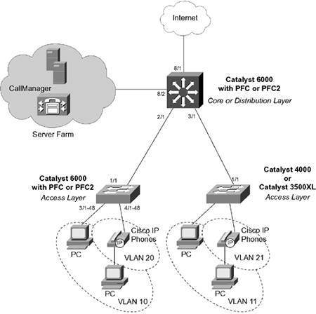
In this example, you want to use QoS to control two types of traffic: Traffic on TCP port 1214 should be policed so that the cumulative rate is no more than 1 Mbps through the distribution switch. IP telephony, on the other hand, should be marked so that it receives the premium level of QoS. Port 2/1 is a Gigabit Ethernet trunk connection to a Catalyst 6000 in the access layer. QoS is port-based, because the access layer switch can examine and mark all traffic on any VLAN within the trunk. Port 3/1 is a Gigabit Ethernet trunk connection to either a Catalyst 4000 or 3500XL in the access layer. These switches are not capable of examining and marking traffic at Layer 3, so the QoS is set to vlan-based (each VLAN is treated independently). The choice of access layer switch has been used to demonstrate the QoS configurations for the different switch platforms. Because we are configuring QoS end-to-end in this network, we can safely assume that the access layer switches will classify and mark IP telephony control traffic (TCP ports 2000 to 2002) to DSCP 26 (AF31) and the Real-Time Transfer Protocol (RTP) or voice bearer packets to DSCP 46 (EF). Port 8/1 is a Gigabit Ethernet connection toward the public Internet. As such, you will not trust any QoS information from that source. Port 8/2 is a Gigabit Ethernet connection into a server farm, where DSCP information can be trusted. The IP telephony server (a Cisco CallManager, for example) is located in the server farm. For those ingress ports that are untrusted, a CoS-to-DSCP map and an IP precedence-to-DSCP map have been configured. These are slightly different from the default map, with adjustments to make CoS 3 map to DSCP 26 (AF31) and CoS 5 map to DSCP 46 (EF). The aggregate policer named Policer-1214 limits the throughput of matching traffic to 1000 kbps or 1 MBps. Traffic that exceeds this rate is dropped. The policer is applied to traffic that matches TCP port 1214 as a source or destination port. The traffic must be matched in both directions, because this is a peer-to-peer protocol, allowing file transfers in either direction. The policer and the matching ACL or class map is applied to ingress ports 2/1, 3/1, and 8/1all the ports where file servers might be present. IP telephony traffic is matched with an ACL on the COS switch and a class map on the IOS switch. TCP port ranges 2000 through 2002 represent IP telephony control traffic, between IP telephones and the CallManager. The DSCP value is set to 26 (AF31) for control traffic. This policy is applied only to VLAN 21, where IP Phones are located on the Catalyst 4000 or 3500XL access layer switches. The Catalyst 6000 access layer switch can do this marking for its IP Phones. The RTP or voice bearer traffic is always marked as CoS 5 by the IP Phones. This is mapped to DSCP 46 (EF) at the ingress ports. Notice that the IOS switch uses a policer to mark the voice control traffic to DSCP 26. This is the only method that can be used for marking DSCP values. Fictitious CIR, burst, and PIR values are given (32000 bps). Because the traffic is transmitted for both conforming and nonconforming, the CIR and burst values don't matter. Finally, the IP telephony traffic is scheduled at the egress port queues. By default, all traffic with CoS 5 (voice bearer traffic) is assigned to the strict-priority queue on all egress ports. A map is defined to assign frames with CoS 3 (IP telephony control traffic) to queue 2 threshold 1. This places the IP telephony control traffic ahead of normal traffic in queue 1, but behind the bearer traffic in the priority queue. The distribution or core Catalyst 6000 switch configuration is shown first:
The configuration for the access layer Catalyst 6000 switch is shown next. Port 1/1 is the uplink into the distribution or core layer, also within the QoS domain. Therefore, DSCP information is trusted. Ports 2/1 to 48 connect to end-user PCs, so the QoS information is untrusted and the inbound CoS values are marked to 0. Ports 3/1 to 48 are connected to Cisco IP Phones. The inbound CoS values are trusted because they have been correctly handled by the IP Phones. The phones have been instructed to consider their access ports as untrusted and to mark their inbound CoS values to 0. These ports are also configured for VLAN-based QoS because all QoS policies will be applied to the voice VLAN as a whole. One access list, ACL-IPT-Control, has been defined to classify IP telephony control traffic (TCP ports 2000 to 2002) and mark the internal DSCP values to 26 (AF31). This is done for all of VLAN 20 traffic. The egress queue scheduling has been configured to assign frames with CoS 3 (IP telephony control traffic) to queue 2 threshold 1 on all 1p2q2t (Gigabit Ethernet) and 2q2t (10/100 phone) ports. By default, frames with CoS 5 (voice bearer traffic) are assigned to the strict priority queues: COS | [View full width] set qos enable set port qos 1/1 trust trust-dscp set port qos 2/1-48 trust untrusted set port qos 2/1-48 cos 0 set port qos 3/1-48 trust trust-cos set port qos 3/1-48 trust-ext untrusted set port qos 3/1-48 vlan-based set qos cos-dscp-map 0 8 16 26 32 46 48 56 set qos ipprec-dscp-map 0 8 16 26 32 46 48 56 set qos acl ip ACL-IPT-Control dscp 26 tcp any any range 2000 2002 commit qos acl ACL-IPT-Control set qos acl map ACL-IPT-Control 20 set qos map 1p2q2t tx 2 1 cos 3 set qos map 2q2t tx 2 1 cos 3
| IOS | N/A |
Finally, the QoS configurations for the Catalyst 4000 (COS) and 3500XL (IOS) access layer switches are shown. Neither switch platform can classify inbound frames. Therefore, only the Catalyst 3500XL is configured to instruct directly connected Cisco IP Phones to rewrite the CoS value of their access ports to 0. The Catalyst 4000 must trust any CoS value that the end device sends. However, some adjustment can be made to its queue scheduling. By default frames with CoS 3 (IP telephony control traffic, for example) are assigned to queue 1 threshold 2, along with CoS 2. Both CoS 3 and CoS 5 (voice bearer traffic) are assigned to queue 2 threshold 1 to improve the overall handling of voice traffic. In this case, it is up to the next higher layer of switches to correctly handle the QoS policies: COS | set qos enable set qos map 2q1t 2 1 cos 3-5
| IOS | (global) interface fast 0/1 (interface) switchport priority extend cos 0 (global) interface fast 0/2 (interface) switchport priority extend cos 0 (global) interface fast 0/3 …
|
Displaying Information About QoS Table 13-9 documents some switch commands that you can use to display helpful information about QoS configuration and operation. Table 13-9. Commands to Display QoS Configuration and Operation InformationDisplay Function | Switch OS | Command |
|---|
QoS port information | COS | show port qos [mod[/port]]
| IOS | [View full width] (exec) show mls qos {type number | port-channel number | vlan vlan-id]
| Port queue scheduling and congestion avoidance | COS | show port qos [mod[/port]]
-OR- show qos info {runtime | config} {mod/port}
-OR- show qos info config port_type {tx |)rx}
| IOS | [View full width] (exec) show queueing interface {type number | Null interface-number | vlan vlan-id}
| QoS mapping | COS | [View full width] show qos maps {config | runtime} [{cos-dscp-map | ipprec-dscp-map | dscp-cos-map | policed-dscp-map {normal-rate | excess-rate}]
| IOS | (exec) show mls qos maps
| Policers | COS | [View full width] show qos policer {config | runtime} {microflow [policer-name] | aggregate [policer-name] | all}
| IOS | (exec) show mls qos aggregate policer [aggregate-name]
| QoS policies | COS | show qos acl editbuffer
-OR- [View full width] show qos acl info default-action {ip | ipx | mac | all} show qos acl info runtime {acl_name | all} show qos acl info config {acl_name | all} [editbuffer [editbuffer_index]]
| IOS | (exec) show class-map [class-name]
-OR- (exec) show policy-map policy-map-name
| Policy activity on an interface | COS | [View full width] show qos acl map {config | runtime} {acl-name | mod/port | vlan | all}
-OR- show qos statistics {mod[/port] | l3stats}
| IOS | [View full width] (exec) show policy-map interface [type number | null interface-number | Vlan vlan-id] [input | output]
|
|