A Basic 3D Drawing Engine
In this section we'll introduce some of the core methods of a basic 3D drawing engine. The file for this 3D engine is draw3d.as , available for download from www.friendsofed.com along with the other example files in this chapter. You can open this file in your favorite text editor to analyze the implementation in more depth. In this section, we will describe the API and take another stab at the spinning cube from the last section.
Our engine uses a single class called Draw3D to store polygonal geometry. It defines several methods to represent the points and lines that make up an object and provides several methods to transform that geometry.
| Draw3D | Method Description |
|---|---|
| Draw3D (pointCount, faceCount) | Constructor; creates a new Draw3D object with the specified number of points and faces allocated |
| Draw3D.setPoint (i, x, y, z) | Sets the point at index i to the coordinates ( x, y, z ) |
| Draw3D.setFace (i, a) | Defines a face at index i with an array of point indices given in a |
| Draw3D.clearTransform () | Clears any transformations that have been applied thus far |
| Draw3D.scale(sx, sy, sz) | Scales (or multiplies) the points in the mesh along the x-, y-, and z-axes by the values sx , sy , and sz , respectively |
| Draw3D.translate(dx, dy, dz) | Translates the points in the mesh along the x-, y-, and z-axes by the distances dx , dy , and dz , respectively |
| Draw3D.rotateX(theta) | Rotates the points in the mesh about the x-axis by an angle of theta radians |
| Draw3D.rotateY(theta) | Rotates the points in the mesh about the y-axis by an angle of theta radians |
| Draw3D.rotateZ(theta) | Rotates the points in the mesh about the z-axis by an angle of theta radians |
| Draw3D.applyPerspective(p) | Applies a simple perspective function using p as the basis for the amount of perspective to apply |
| Draw3D.setFillColor(r, g, b) | Sets the fill color to use when rendering polygons |
| Draw3D.setFillAlpha(alpha) | Sets the fill alpha to use when rendering polygons |
| Draw3D.setLineColor(r, g, b) | Sets the line color to use when rendering polygons |
| Draw3D.setLineWeight(w) | Sets the line thickness to w |
| Draw3D.setShadeOn() | Turns on a very simple lighting and shading model |
| Draw3D.setShadeOff() | Turns off the simple lighting and shading model |
| Draw3D.render() | Renders the scene |
The render method is really the heart of the engine. Once the geometry and its transformations have been set up, render translates that information into drawing functions that Flash understands. This rendering function is slightly more intelligent than the loop you used to draw the wire frame cube in the last example. It sorts the faces so those that are supposed to be in front are on top of faces that should be in back. It also uses information about the face to compute its relationship to a fixed light source, which in turn can be used to alter the shading of the faces.
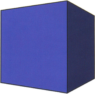
With these new features, you should really be able to improve the last example. For this example, refer to the file drawing8.fla .
-
Create a new movie and set the window dimensions to 400x400. Using the infrastructure developed in draw3d.as (incorporated via the #include command) you can re-create your cube.
Select frame 1 on the timeline and add the following code. The script begins by creating an array of points with the coordinates of the cube:
#include "draw3d.as" // Initialize the 3d drawing object with 8 points and 6 faces m = new Draw3D (8, 6); // Define the point list m.setPoint (0, 100, 100, -100); // Point 0 m.setPoint (1, 100, -100, -100); // Point 1 m.setPoint (2, -100, -100, -100); // Point 2 m.setPoint (3, -100, 100, -100); // Point 3 m.setPoint (4, 100, 100, 100); // Point 4 m.setPoint (5, 100, -100, 100); // Point 5 m.setPoint (6, -100, -100, 100); // Point 6 m.setPoint (7, -100, 100, 100); // Point 7 // Set the fill and line properties m.setShadeOn (); m.setLineWeight (2); m.setLineColor (0, 0, 0); m.setFillColor (.4, .4, .8); // Define the faces m.setFace (0, new Array (0, 1, 2, 3)); m.setFace (1, new Array (4, 7, 6, 5)); m.setFace (2, new Array (0, 4, 5, 1)); m.setFace (3, new Array (1, 5, 6, 2)); m.setFace (4, new Array (2, 6, 7, 3)); m.setFace (5, new Array (4, 0, 3, 7));
-
You may be wondering why we have one list of vertices and then each face has a list of indices into that list of vertices. Wouldn't it be easier to have a point list for each face rather than a combined point list? A cube has eight points that need to be transformed, but if each face has its own point list, then there are 24 points we will need to transform (6 faces multiplied by 4 points per face equates to 24 points). That's quite a few redundant calculations! In addition to being more computationally efficient, this scheme makes it easier to update point values.
To finish the program, add on this onEnterFrame function that effectively renders your cube:
theta = 0; m.scene.onEnterFrame = function() { with (_root) { m.clearTransform(); m.rotateY (theta); m.applyPerspective (500); theta += .02; if (theta > 6.282) theta -= 6.282; m.render (); } };
 -
Finally, test your movie (CTRL/CMD+ENTER).
3D Transformations
We mentioned transformations earlier, and we just used the clearTransform method, but we haven't really described them in detail. Three of the most common 3D transformations are translation, scaling, and rotation. These operations allow us to change the position, size , and orientation of objects in a scene.
In many advanced 3D systems, all transformations are represented as 4x4 matrices. This is useful because one transformation matrix can be multiplied by another transformation matrix to create an aggregate transformation matrix. Multiplying the transformation matrix by a position vector results in a transformed position vector.
In complex systems, this can be an efficient way of applying a complex transformation to a large number of points. This is useful in 3D games , medical imaging applications, and scientific visualization applications that often must deal with thousands or even millions of points, and numerous transformations. The 3D transformations we will introduce are slightly less complex. These operations will be applied directly to the points that we are transforming instead of to an intermediate transformation matrix.
If you're starting to get a little worried about how freely we're using mathematical terms such as vector and matrix, just relax. We're going to explain how and why the math does what it does, but if you don't completely get it, that's OK ”it's more important that you understand the high-level concepts and why they work, if not how.
Our 3D drawing engine defines four transformations: translation, scaling, rotation, and perspective. We will now examine each operation a little closer.
Translation
Translation boils down to simple addition. In ActionScript, you could translate a point p by values tx , ty , and tz like this:
p[0] += tx; p[1] += ty; p[2] += tz;
After this transformation, p will be offset along the x-, y-, and z-axes by distances tx , ty , and tz , respectively.
Scaling
Scaling is equivalent to multiplication. In ActionScript, you could scale a point p by values sx , sy , and sz like this:
p[0] *= sx; p[1] *= sy; p[2] *= sz;
Rotation
Rotation is measured as an angle about an axis. Our 3D drawing engine defines rotation transformations about the x-, y-, and z-axes. With these three functions it is then possible to represent any arbitrary rotation as being made up of x, y, and z rotational components .
A point p can be rotated about the x-axis with the following ActionScript:
y = p[1]*Math.cos(theta) - p[2]*Math.sin(theta); z = p[1]*Math.sin(theta) + p[2]*Math.cos(theta); p[1] = y; p[2] = z;
The point p can be rotated about the y-axis with the next code snippet:
z = p[2]*Math.cos(theta) - p[0]*Math.sin(theta); x = p[2]*Math.sin(theta) + p[0]*Math.cos(theta); p[2] = z; p[0] = x;
And finally, point p can be rotated about the z-axis using this code:
x = p[0]*Math.cos(theta) - p[1]*Math.sin(theta); y = p[0]*Math.sin(theta) + p[1]*Math.cos(theta); p[0] = x; p[1] = y;
Notice that when we rotate a point about a particular axis, the value associated with that axis does not change.
View Transformation and Perspective
When you look at the two-dimensional floor plan of a house, you are viewing what is called a parallel projection. In a parallel projection, the x- and y-axes of the screen or viewing surface correspond to the x- and y-axes of the scene. The imaginary lines, or rays, that we use to project points from 3D space onto the 2D projection plane are parallel. In parallel projections, objects do not change size when they move in a direction perpendicular to the plane of projection.
What we would like to develop is a transformation that imparts a sense of perspective. We will use a very simple equation to find a value perspective that we will multiply by the point's x and y values:

The value c can be tweaked to adjust the amount of perspective. As c gets larger the perspective effect lessens.
The corresponding ActionScript code to transform a point p with the constant c is thus:
if (c-p[2] == 0) perspective = 1; else p = perspective / p[2] + perspective; if (c <= 0) perspective = 1; p[0] *= perspective; p[1] *= perspective;