2.2 Token Ring Frame Formats
2.2 Token Ring Frame Formats
Three types of frame formats are supported on a Token Ring network: token, abort, and frame. The token format as illustrated in Figure 2.6 (a) is the mechanism by which access to the ring is passed from one computer attached to the network to another device connected to the network. Here, the token format consists of three bytes, of which the starting and ending delimiters are used to indicate the beginning and end of a token frame. The middle byte of a token frame is an access control byte. Three bits are used as a priority indicator, three bits are used as a reservation indicator, while one bit is used for the token bit, and another bit position functions as the monitor bit.
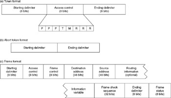
Figure 2.6: Token, Abort, and Frame Formats
When the token bit is set to a binary 0, it indicates that the transmission is a token. When it is set to a binary 1, it indicates that data in the form of a frame is being transmitted.
The second Token Ring frame format signifies an abort token. In actuality, there is no token, because this format is indicated by a starting delimiter followed by an ending delimiter . The transmission of an abort token is used to abort a previous transmission. The format of an abort token is illustrated in Figure 2.6b.
The third type of Token Ring frame format occurs when a station seizes a free token. At that time the token format is converted into a frame that includes the addition of frame control, addressing data, an error detection field, and a frame status field. The format of a Token Ring frame is illustrated in Figure 2.6c.
2.2.1 Frame Composition
By examining each of the fields in the Token Ring frame, we can examine the token and abort token frames due to the commonality of fields between each frame. Note that, excluding the optional routing field, there are a total of 21 bytes of overhead associated with a Token Ring frame.
2.2.2 Starting/Ending Delimiters
The starting and ending delimiters mark the beginning and end of a token or frame. Each delimiter consists of a unique code pattern that identifies it to the network. To understand the composition of the starting and ending delimiter fields requires us to review the method by which data is represented on a Token Ring network using Differential Manchester encoding.
2.2.2.1 Differential Manchester Encoding
Figure 2.7 illustrates the use of Differential Manchester encoding, comparing its operation to non-return to zero (NRZ) and conventional Manchester encoding.
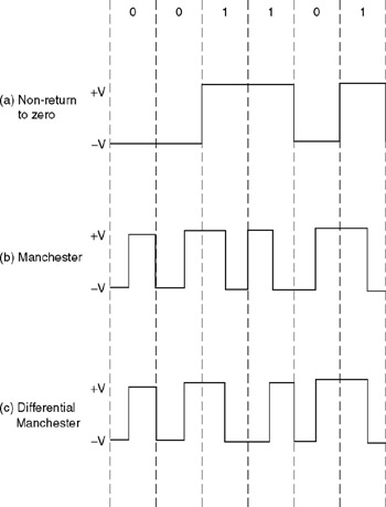
Figure 2.7: Differential Manchester Encoding
In Figure 2.7 (a), NRZ coding illustrates the representation of data by holding a voltage low ( ˆ’ V) to represent a binary 0 and high (+V) to represent a binary 1. This method of signaling is called non-return to zero because there is no return to a 0 V position after each data bit is coded.
One problem associated with NRZ encoding is the fact that a long string of 0 or 1 bits does not result in a voltage change. Thus, to determine that bit m in a string of n bits of 0's or 1's is set to a 0 or 1 requires sampling at predefined bit times. This, in turn , requires each device on a network using NRZ encoding to have its own clocking circuitry .
To avoid the necessity of building clocking circuitry into devices requires a mechanism for encoded data to carry clocking information. One method by which encoded data carries clocking information is obtained from the use of Manchester encoding, which is illustrated in Figure 2.7b. In Manchester encoding, each data bit consists of a half-bit time signal at a low voltage ( ˆ’ V) and another half-bit time signal at the opposite positive voltage (V). Every binary 0 is represented by a half-bit time at a low voltage and the remaining half-bit time at a high voltage. Every binary 1 is represented by a half-bit time at a high voltage followed by a half-bit time at a low voltage. By changing the voltage for every binary digit, Manchester encoding ensures that the signal carries self-clocking information.
Figure 2.7c illustrates Differential Manchester encoding. The difference between Manchester encoding and Differential Manchester encoding occurs in the method by which binary 1's are encoded. In Differential Manchester encoding, the direction of the signal's voltage transition changes whenever a binary 1 is transmitted, but remains the same for a binary 0. The IEEE 802.5 standard specifies the use of Differential Manchester encoding, and this encoding technique is used on Token Ring networks at the physical layer to transmit and detect four distinct symbols: a binary 0, a binary 1, and two non-data symbols.
2.2.2.2 Non-Data Symbols
Under Manchester and Differential Manchester encoding, there are two possible code violations that can occur. Each code violation produces what is known as a non-data symbol and is used in the Token Ring frame to denote starting and ending delimiters similar to the use of the flag in an HDLC (High-level Data-Link Control) frame. However, unlike the flag whose bit composition, 01111110, is uniquely maintained by inserting a 0 bit after every sequence of five set bits and removing a 0 following every sequence of five set bits, Differential Manchester encoding maintains the uniqueness of frames by the use of non-data J and non-data K symbols. This eliminates the bit stuffing operations required by HDLC.
The two non-data symbols each consist of two half-bit times without a voltage change. The J symbol occurs when the voltage is the same as that of the last signal, while the K symbol occurs when the voltage becomes opposite of that of the last signal. Figure 2.8 illustrates the occurrence of the J and K non-data symbols based upon different last bit voltages. Readers will note in comparing Figure 2.8 to Figure 2.7c that the J and K non-data symbols are distinct code violations that cannot be mistaken for either a binary 0 or a binary 1.
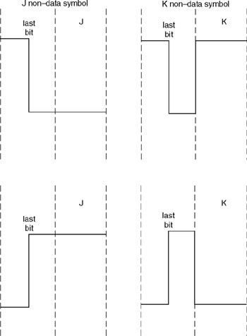
Figure 2.8: J and K Non-Data Symbol Composition
Now that we have an understanding of the operation of Differential Manchester encoding and the composition of the J and K non-data symbols, we can focus our attention on the actual format of each frame delimiter.
The start delimiter field marks the beginning of a frame. The composition of this field is the bits and non-data symbols JK0JK000. The end delimiter field marks the end of a frame as well as denotes whether or not the frame is the last frame of a multiple frame sequence using a single token or if there are additional frames following this frame. The format of the end delimiter field is JK1JK1IE, where I is the intermediate frame bit. If I is set to 0, this indicates that it is the last frame transmitted by a station. If I is set to 1, this indicates that additional frames follow this frame. E is an errordetected bit. The E bit is initially set to 0 by the station transmitting a frame, token, or abort sequence. As the frame circulates the ring, each station checks the transmission for errors. Upon detection of a frame check sequence (FCS) error, inappropriate non-data symbol, illegal framing, or another type of error, the first station detecting the error will set the E bit to a value of 1. Because stations keep track of the number of times they set the E bit to a value of 1, it becomes possible to use this information as a guide to locating possible cable errors. For example, if one workstation accounted for a very large percentage of E bit settings in a 72-station network, there is a high degree of probability that there is a problem with the lobe cable to that workstation. The problem could be a crimped cable or a loose connector and represents a logical place to commence an investigation in an attempt to reduce E bit errors.
2.2.3 Access Control Field
The second field in both token and frame formats is the access control byte. As illustrated in Figure 2.6a, this byte consists of four subfields and serves as the controlling mechanism for gaining access to the network. When a free token circulates the network, the access control field represents one third of the length of the frame because it is prefixed by the start delimiter and suffixed by the end delimiter.
The lowest priority that can be specified by the priority bits in the access control byte is 0 (000), while the highest is seven (111), thus providing eight levels of priority. Table 2.3 lists the normal use of the priority bits in the access control field. Workstations have a default priority of three, while bridges have a default priority of four.
| Priority Bits | Priority |
|---|---|
| 000 | Normal user priority, MAC frames that do not require a token and response type MAC frames |
| 001 | Normal user priority |
| 010 | Normal user priority |
| 011 | Normal user priority and MAC frames that require tokens |
| 100 | Bridge |
| 101 | Reserved |
| 110 | Reserved |
| 111 | Specialized station management |
To reserve a token, a workstation inserts its priority level in the priority reservation subfield. Unless another station with a higher priority bumps the requesting station, the reservation will be honored and the requesting station will obtain the token. If the token bit is set to 1, this serves as an indication that a frame follows instead of the ending delimiter.
A station that needs to transmit a frame at a given priority can use any available token that has a priority level equal to or less than the priority level of the frame to be transmitted. When a token of equal or lower priority is not available, the ring station can reserve a token of the required priority through the use of the reservation bits. In doing so, the station must follow two rules. First, if a passing token has a higher priority reservation than the reservation level desired by the workstation, the station will not alter the reservation field contents. Second, if the reservation bits have not been set or indicate a lower priority than that desired by the station, the station can now set the reservation bits to the required priority level.
Once a frame is removed by its originating station, the reservation bits in the header will be checked. If those bits have a non-zero value, the station must release a non-zero priority token, with the actual priority assigned based upon the priority used by the station for the recently transmitted frame, the reservation bit settings received upon the return of the frame, and any stored priority.
On occasion, the Token Ring protocol will result in the transmission of a new token by a station prior to that station having the ability to verify the settings of the access control field in a returned frame. When this situation arises, the token will be issued according to the priority and reservation bit settings in the access control field of the transmitted frame.
Figure 2.9 illustrates the operation of the priority (P) and reservation (R) bit fields in the access control field. In this example, preventing a high-priority station from monopolizing the network is illustrated by station A entering a priority-hold state. This occurs when a station originates a token at a higher priority than the last token it generated. Once in a priority-hold state, the station will issue tokens that will bring the priority level eventually down to zero as a mechanism to prevent a high-priority station from monopolizing the network.
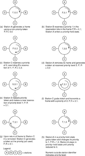
Figure 2.9: Priority and Reservation Field Utilization
2.2.3.1 The Monitor Bit
The monitor bit is used to prevent a token with a priority exceeding zero or a frame from continuously circulating on the Token Ring. This bit is transmitted as a 0 in all tokens and frames, except for a device on the network that functions as an active monitor and thus obtains the capability to inspect and modify that bit. When a token or frame is examined by the active monitor, it will set the monitor bit to 1 if it was previously found to be set to 0. If a token or frame is found to have the monitor bit already set to 1, this indicates that the token or frame has already made at least one revolution around the ring and an error condition has occurred, usually caused by the failure of a station to remove its transmission from the ring or the failure of a high-priority station to seize a token. When the active monitor finds a monitor bit set to 1, it assumes an error condition has occurred. The active monitor then purges the token or frame and releases a new token onto the ring.
Now that we have an understanding of the role of the monitor bit in the access control field and the operation of the active monitor on that bit, let us focus our attention on the active monitor.
2.2.3.2 Active Monitor
The active monitor is the device that has the highest address on the network. All other stations on the network are considered standby monitors and watch the active monitor.
As previously explained, the function of the active monitor is to determine if a token or frame is continuously circulating the ring in error. To accomplish this, the active monitor sets the monitor count bit as a token or frame goes by. If a destination workstation fails or has its power turned off, the frame will circulate back to the active monitor, where it is then removed from the network. In the event the active monitor should fail or be turned off, the standby monitors watch the active monitor by looking for an active monitor frame. If one does not appear within seven seconds, the standby monitor that has the highest network address then takes over as the active monitor.
2.2.4 Frame Control Field
The frame control field informs a receiving device on the network of the type of frame that was transmitted and how it should be interpreted. Frames can be either Logical Link Control (LLC) or reference physical link functions according to the IEEE 802.5 Media Access Control (MAC) standard. A MAC frame carries network control information and responses, while an LLC frame carries data.
The eight-bit frame control field has the format FFZZZZZZ, where FF are frame definition bits. The top of Table 2.4 indicates the possible settings of the frame bits and the assignment of those settings. The ZZZZZZ bits convey MAC buffering information when the FF bits are set to 00. When the FF bits are set to 01 to indicate an LLC frame, the ZZZZZZ bits are split into two fields, designated rrrYYY. Currently, the rrr bits are reserved for future use and are set to 000. The YYY bits indicate the priority of the LLC data. The lower portion of Table 2.4 indicates the value of the Z bits when used in MAC frames to notify a Token Ring adapter that the frame is to be expressed buffered.
| Frame Type Field | |
|---|---|
| F bit settings | Assignment |
| 00 | MAC frame |
| 01 | LLC frame |
| 10 | Undefined (reserved for future use) |
| 11 | Undefined (reserved for future use) |
| Z bit settings | Assignment [a] |
| 000 | Normal buffering |
| 001 | Remove ring station |
| 010 | Beacon |
| 011 | Claim token |
| 100 | Ring purge |
| 101 | Active monitor present |
| 110 | Standby monitor present |
| [a] When F bits set to 00, Z bits are used to notify an adapter that the frame is to be expressed buffered. | |
2.2.5 Destination Address Field
Although the IEEE 802.5 standard is similar to Ethernet in that it supports both 16-bit and 48-bit address fields, IBM's implementation requires the use of 48-bit address fields and almost all Token Ring networks use six-byte address fields today. The destination address field is made up of five subfields, as illustrated in Figure 2.10. The first bit in the destination address identifies the destination as an individual station (bit set to 0) or as a group (bit set to 1) of one or more stations. The latter provides the capability for a message to be broadcast to a group of stations.
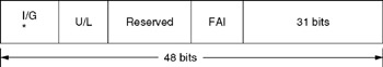
Figure 2.10: Destination Address Subfields
2.2.5.1 Universally Administered Address
Similar to Ethernet, the Token Ring universally administered address is a unique address permanently encoded into an adapter's ROM. Because it is placed into ROM, it is also known as a burned-in address. The IEEE assigns blocks of addresses to each vendor manufacturing Token Ring equipment, which ensures that Token Ring adapter cards manufactured by different vendors are uniquely defined. Some Token-Ring adapter manufacturers are assigned universal addresses that contain an organizationally unique identifier. This identifier consists of the first six hex digits of the adapter card address and is also referred to as the manufacturer identification. For example, cards manufactured by IBM will begin with the address hex X08005A or hex X10005A, whereas adapter cards manufactured by Texas Instruments will begin with the address hex X400014.
2.2.5.2 Locally Administered Address
A key problem with the use of universally administered addresses is the requirement to change software coding in a mainframe computer whenever a workstation connected to the mainframe via a gateway is added or removed from the network. To avoid constant software changes, locally administrated addressing can be used. This type of addressing temporarily overrides universally administrated addressing; however, the user is now responsible for ensuring the uniqueness of each address.
2.2.5.3 Functional Address Indicator
The functional address indicator subfield in the destination address identifies the function associated with the destination address, such as a bridge, active monitor, or configuration report server.
The functional address indicator indicates a functional address when it is set to 0 and the I/G bit position is set to a 1, the latter indicating a group address. This condition can only occur when the U/L bit position is also set to 1 and results in the ability to generate locally administered group addresses called functional addresses. Table 2.5 lists the functional addresses defined by the IEEE. Currently, 14 functional addresses have been defined, out of a total of 31 that are available for use, with the remaining addresses available for user definitions or reserved for future use.
| Active Monitor | XC000 0000 0001 |
| Ring Parameter Server | XC000 0000 0002 |
| Network Server Heartbeat | XC000 0000 0004 |
| Ring Error Monitor | XC000 0000 0008 |
| Configuration Report Server | XC000 0000 0010 |
| Synchronous Bandwidth Manager | XC000 0000 0020 |
| Locate - Directory Server | XC000 0000 0040 |
| NETBIOS | XC000 0000 0080 |
| Bridge | XC000 0000 0100 |
| IMPL Server | XC000 0000 0200 |
| Ring Authorization Server | XC000 0000 0400 |
| LAN Gateway | XC000 0000 0800 |
| Ring Wiring Concentrator | XC000 0000 1000 |
| LAN Manager | XC000 0000 2000 |
| User-defined | XC000 0000 8000 |
2.2.5.4 Address Values
The range of addresses that can be used on a Token Ring primarily depends on the settings of the I/G, U/L, and FAI bit positions. When the I/G and U/L bit positions are set to 00, the manufacturer's universal address is used. When the I/G and U/L bits are set to 01, individual locally administered addresses are used in the defined range listed in Table 2.5. When all three bit positions are set, this situation indicates a group address within the range contained in Table 2.6. If the I/G and U/L bits are set to 11 but the FAI bit is set to 0, this indicates that the address is a functional address. In this situation, the range of addresses is bit sensitive, permitting only those functional addresses previously listed in Table 2.5.
| Bit Settings | ||||
|---|---|---|---|---|
| I/G | U/L | FAI | Address/Address Range | |
| Individual, universally administered |
|
| 0/1 | Manufacturer's serial number |
| Individual, locally administered |
| 1 |
| X4000 0000 0000 to X4000 7FFF FFFF |
| Group address | 1 | 1 | 1 | XC000 8000 0000 to XC000 FFFF FFFF |
| Functional address | 1 | 1 |
| XC000 0000 0001 to XC000 0000 2000 (bit-sensitive) |
| All stations broadcast | 1 | 1 | 1 | XFFFF FFFF FFFF |
| Null address |
|
|
| X0000 0000 0000 |
In addition to the previously mentioned addresses, there are two special destination address values that are defined. An address of all 1's (hex FFFFFFFFFFFF) identifies all stations as destination stations. If a null address is used in which all bits are set to 0 (hex 000000000000), the frame is not addressed to any workstation. In this situation, it can only be transmitted but not received, enabling you to test the ability of the active monitor to purge this type of frame from the network.
2.2.6 Source Address Field
The source address field always represents an individual address that specifies the adapter card responsible for the transmission. The source address field consists of three major subfields, as illustrated in Figure 2.11. When locally administered addressing occurs, only 24 bits in the address field are used because the 22 manufacturer identification bit positions are not used.
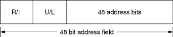
Figure 2.11: Source Address Field
The routing information bit identifier (R/I) identifies the fact that routing information is contained in an optional routing information field. This bit is set when a frame will be routed across a bridge using IBM's source routing technique.
2.2.7 Routing Information Field
The routing information field (RIF) is optional and is included in a frame when the RI bit of the source address field is set. Figure 2.12 illustrates the format of the optional routing information field. If this field is omitted, the frame cannot leave the ring it originated on under IBM's source routing bridging method. Under transparent bridging, the frame can be transmitted onto another ring. The routing information field is of variable length and contains a control subfield and one or more two-byte route designator fields when included in a frame, as the latter are required to control the flow of frames across one or more bridges.
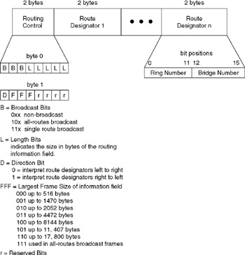
Figure 2.12: Routing Information Field
The maximum length of the routing information field (RIF) supported by IBM is 18 bytes. Because each RIF must contain a two-byte routing control field, this leaves a maximum of 16 bytes available for use by up to eight route designators. As illustrated in Figure 2.12, each two-byte route designator consists of a 12-bit ring number and a four-bit bridge number. Thus, a maximum total of 16 bridges can be used to join any two rings in an Enterprise Token Ring network.
2.2.8 Information Field
The information field is used to contain Token Ring commands and responses as well as carry user data. The type of data carried by the information field depends on the F bit settings in the frame type field. If the F bits are set to 00, the information field carries Media Access Control (MAC) commands and responses that are used for network management operations. If the F bits are set to 01, the information field carries Logical Link Control (LLC) or user data. Such data can be in the form of portions of a file being transferred on the network or an electronic mail message being routed to another workstation on the network. The information field is of variable length and can be considered to represent the higher-level protocol enveloped in a Token Ring frame.
In the IBM implementation of the IEEE 802.5 Token Ring standard, the maximum length of the information field depends on the Token Ring adapter used and the operating rate of the network. Token Ring adapters with 64 K bytes of memory can handle up to 4.5 K bytes on a 4-Mbps network and up to 18 K bytes on a 16-Mbps network.
2.2.9 Frame Check Sequence Field
The frame check sequence (FCS) field contains four bytes that provide the mechanism for checking the accuracy of frames flowing on the network. The cyclic redundancy check data included in the FCS field covers the frame control, destination address, source address, routing information, and information fields. If an adapter computes a cyclic redundancy check that does not match the data contained in the frame check sequence field of a frame, the destination adapter discards the frame information and sets an error bit (E bit) indicator. This error bit indicator, as previously discussed, actually represents a ninth bit position of the ending delimiter and serves to inform the transmitting station that the data was received in error.
2.2.10 Frame Status Field
The frame status field serves as a mechanism to indicate the results of a frame's circulation around a ring to the station that initiated the frame. Figure 2.13 indicates the format of the frame status field. The frame status field contains three subfields that are duplicated for accuracy purposes because they reside outside of CRC checking. One field (A) is used to denote if an address was recognized, while a second field (C) indicates if the frame was copied at its destination. Each of these fields is one bit in length. The third field (rr), which is two bit positions in length, is currently reserved for future use.
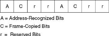
Figure 2.13: Frame Status Field
EAN: 2147483647
Pages: 111