Modulation and Line-Coding Techniques in Wired Networks
| Modulation and demodulation are processes of converting the analog signals to digital signals and vice versa. The signal transformation from analog form to digital form is based on analog signal-to-discrete signal converters, which are known as analog-to-digital converters (ADCs), digital-to-analog converters (DACs), coder -decoders (codecs), and data service unit/channel service units (DSU/CSUs). The analog systems can still carry voice, data, and video, but are mostly designed for voice communications. The most used technique for voice digitalization is pulse code modulation (PCM). In PCM, at least 8000 analog samples of voice are required to characterize the human voice. The previous suggestion is based on the following two theorems: First, Nyquist's Theorem defines the following law:
Second, Nyquist's sampling theorem requires the following:
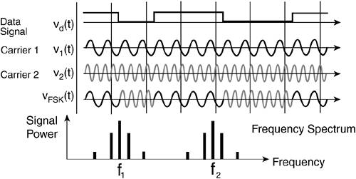
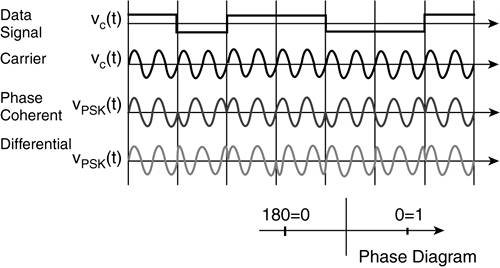
NOTE A source for Nyquist's sampling theorem is The Telecommunications Fact Book and Illustrated Dictionary by Khan S. Ahmed (Delma Publishers Inc., 1992). Nyquist's sampling theorem states that digital sampling must take place at twice the highest frequency to reconstruct the analog signal accurately. As a result, the sampling theorem requires that, given fa = 4-kHz frequency band , fs To convert analog to digital, a binary code needs to be assigned to every analog sample. An 8-bit code provides 256 levels, and enables the quality of the recovered voice to be comparable with the analog voice. The 8000 samples/second times 8 bits per sample, yields the 64 kbps necessary for a single voice channel. Good voice reproduction can be achieved using a 7-bit code per sample, and the resulting overall voice channel is 8000 samples/second times 7 bits per sample, yielding 56 kbps. Regeneration of the signal is primarily based on the use of repeaters that are necessary because of attenuation of the signal. Amplitude, Frequency, and Phase ModulationsIn general, modulation and demodulation are always related to one of the three characteristics of the signalamplitude, frequency, and phaseor a combination of all or some of these characteristics. Modulation, or shifting, of any of these characteristics creates a recognizable, adequate (or sometimes called constellation) state of the signal, interprets these states as 1 or 0, and digitalizes them. In amplitude-shift keying (ASK), the 1 and 0 are represented by two different amplitudes, as shown in Figure 2-1. In some cases, instead of using two amplitudes it is more acceptable to use an amplitude and no signal, in which case the timing is crucial. ASK can be used to code more than one bit. In cases when two recognizable amplitudes are generated, the technique can code-decode 2 bits with 4 stable states: 00, 01, 10, and 11. In copper lines this technique is considered inefficient because amplitude changes (power, attenuation, interference) can generate errors. In fiber media, where the attenuation of the signal is less of a consideration, 1 can be represented as a shot pulse of light, or high-amplitude light, and 0 can be low-amplitude light or the absence of light. Figure 2-1. Amplitude-Shift Keying (ASK) Scheme Frequency-shift keying (FSK) uses at least two different frequencies to represent 1 and 0, as shown in Figure 2-2. The scheme is less susceptible to errors than ASK and it is used for low-speed data transmissions. Figure 2-2. Frequency-Shift Keying (FSK) Scheme In phase-shift keying (PSK), 1 and 0 are coded using different phases of the signal, as shown in Figure 2-3. The signal burst of the same phase represents 0, and the signal burst of the opposite phase represents 1. This technique is more resistant to errors than ASK and FSK, but it can still be used for low-rate data transmissions. Figure 2-3. Phase-Shift Keying (PSK) Scheme Quadrature Amplitude ModulationQuadrature amplitude modulation (QAM) is a line-coding technique that has been used in modems for over twenty years . This technology can also be referred to as 16QAM or 4/4QAM. QAM takes advantage of the fact that if two signals are shifted to 90 degrees from each other, they can be sent simultaneously over the same frequency band. The two signals are ASK modulated, but on the receiving side they are de-shifted and the original binary codes are obtained. In general, the signal is divided by 2 and the resulting signal S(t) can be represented as the following:
In simple terms, QAM modulates the amplitudes of two waves, and instead of using +-1, QAM uses 4 different amplitudes for each of the waves. As a result, there are four instead of two amplitude modulations: A1, A2, A3, and A4. The full combination of amplitude modulations and S(t) provides 16 combinations per Hertz, which is otherwise called 4 bps or 4 baud. The 16 established constellations look like 0000, 0001, ... (to 1111). xDSL Coding TechniquesThe emergence of digital subscriber line (DSL) technology increased the need for more modulation techniques. Unlike other technologies, DSL uses a set of protocols that are suitable for the different types of DSL technologies. Asymmetric DSL (ADSL), in particular, refers to the family of coding schemes where the emerging Internet technologies usually require higher bandwidth in the downstream direction than in the upstream direction (see the section, "xDSL Services" in Chapter 1, "Remote Access Overview"). This fact provides the need to divide the available bandwidth asymmetrically and to provide different data rates for each direction. In terms of Cisco IOS, Cisco ADSL solutions support the following DSL operating modes: ansi-dmt, auto detect mode, itu-dmt, and splitterless (G.lite) mode. Discrete Multi-ToneDiscrete Multi-Tone (DMT) uses multiple carrier signals at different frequencies, sending some bits on each channel. The term DMT comes from the fact that each discrete bin is at a specific frequency or tone. The available transmission band is divided into several base-band carriers , sometimes called subchannels . Upon the initialization phase, the DMT modulator sends out a test signal on each subchannel to determine the signalto-noise ratio. The modulator then assigns more bits to channels with better signal transmission quality and less to the channels with poorer quality. DMT modulation is actually a form of frequency-division multiplexing (FDM). The input data stream is split into 256 channels that have the same bandwidth, but a different center frequency, otherwise called the channel number. Cisco uses the following standard DMT modulations in its productsITU-DMT(G.992.1 TU G.DMT), ITU-T G.992.2 (G.lite), ANSI-DMT(ANSI Standard T1.413) and auto-recognition ADSL mode. Example 2-1 shows a sample of Cisco's ADSL 827 router showing the content of the bins . Example 2-1. A Sample of Cisco's ADSL 827 Router Showing the Content of the Bins pnedeltc-dsl# sh controllers atm 0 <output omitted> DMT Bits Per Bin 00: 0 0 0 0 0 0 0 5 4 5 5 5 6 6 6 6 10: 6 6 6 6 6 5 6 5 6 6 5 6 5 6 6 0 20: 0 0 0 0 0 0 4 5 5 6 6 6 7 7 7 8 30: 8 7 8 8 8 8 8 8 8 8 8 8 8 8 8 8 40: 9 9 9 9 9 9 9 9 9 9 9 9 A A A A 50: A A A A A A 2 A A A A A A A A A 60: 9 A 9 9 9 9 9 9 9 9 9 9 9 9 9 9 70: 9 9 9 9 9 9 9 9 9 9 9 9 9 9 9 9 80: 9 9 9 9 8 8 9 9 8 8 8 8 8 8 8 8 90: 8 8 8 8 8 8 8 8 8 8 8 8 8 8 8 8 A0: 8 8 8 8 8 8 8 8 8 8 8 8 7 7 7 7 B0: 7 7 7 7 7 7 7 7 7 7 7 7 5 7 7 7 C0: 7 7 7 7 7 7 7 7 7 7 7 7 7 7 7 7 D0: 7 7 7 7 7 7 7 7 7 7 7 7 7 7 6 6 E0: 6 6 6 6 6 6 6 6 6 6 6 6 6 6 6 6 F0: 6 6 5 5 5 4 4 2 2 0 0 0 0 0 0 0 <output omitted> Every row has 16 (10h) columns (bins), where the first seven 0s are the voice (POTS) and guard channels. The following 24 non-zero bins, which results in about a 103-MHz band, are the upstream channels, followed by 6 bins of guard channels. The last group of 224 bins represent 224 downstream channels. Every bin is QAM modulated, and every value is calculated, based on the following formula:
Using multiple narrowband (baseband) channels results in the following advantages:
The ANSI ADSL system uses 256 frequency channels or bins. Data is separately modulated into each bin based on how much data each bin can hold. The amount of data each bin can hold is a function of loop characteristics and frequency. All channels have a bandwidth of 4.3125 kHz and the frequency difference between two successive channels is also 4.3125 kHz. This technology uses frequency bands above the POTS spectrum to pass ADSL data both upstream and downstream. The upstream band is from approximately 25 kHz to about 138 kHz, and the downstream band starts at 142 kHz (25 kHz if echo cancellation is used) and extends to 1.1 MHz. Each of these bands is further subdivided into 4.3125-kHz bins. Data is separately modulated into each bin based on how much data each bin can hold. The amount of data each bin can hold is a function of loop characteristics and frequency. A new batch of data is sent in each bin 4000 times a second. At the next layer up in the protocol stack, a Super Frame (SF) structure is defined. The SF structure defines how the payload data and overhead data is assembled . Additionally, it defines how the data in the SF is allocated to the binshere, Cisco defines interleave mode and fast mode, where interleave mode performs Reed-Solomon error correction. DMT is generally accepted to be better at rate adaptation (changing speed because of line conditions), varying loop conditions (bridge taps, mixed gauges), noise and crosstalk handling, and it is better for voice purposes. Carrierless Amplitude/Phase ModulationCarrierless amplitude/phase modulation (CAP) (also referred to as ATR-R) enables simple echo cancellation (although many CAP products use FDM), provides less delay (only 25 percent compared to DMT), and provides simplicity and maturity (because it is based on QAM). CAP can be referred to as an improved or suppressed QAM because, unlike QAM, CAP does not send a carrier over the line because the carrier does not carry any information. Generally speaking, if you add a rotation to the receiver side and suppress the carrier from the sender, you can get CAP from QAM. The technology is based on phase shifting (see the beginning of this chapter), but the phase of the wave changes under certain angles and it is measured from the current phase of the carrier, and not from some absolute reference phase. Because it is not absolute phase shifting, it is differential. In the simplest scenario with two phases, 1 is shifting (rotating) the phase to 180 degrees, and 0 is shifting to 0 degrees, or vice versa. This can be improved if you add two more established constellations. Because of quadrature phase-shift keying (QPSK), the signal is already sent as a combination of sine waves and cosine waves at carrier frequency, and they are already shifted by 90 degrees. QPSK as a coding technique takes its name from the term perpendicular , or quadrature. However, there is no phase shifting because the two waves are already shifted (phased, rotated ), and CAP simply modulates the two amplitudes. Recently, CAP has been driven primarily by ANSI and is considered an option to DMT. |
 2fa
2fa 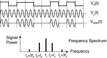
EAN: 2147483647
Pages: 235