Internet Technologies and Remote Access VPNs
| In this section, issues are briefly covered that are specific to three popular technologies that offer broadband services for most remote access VPNs:
VPN and ADSLA typical ADSL architecture is composed of equipment at the ADSL point of presence (POP) and customer premises equipment (CPE). Network access providers (NAPs) manage Layer 2 network cores, and network service providers (NSPs) manage Layer 3 network cores. These roles are divided or shared among incumbent local exchange carriers (ILECs), competitive local exchange carriers (CLECs), and Tier 1 and Tier 2 Internet service providers (ISPs). CPEs can consist of PCs or workstations, remote ADSL terminating units (ATU-Rs), and routers. For example, a residential user might have a single PC connected through Ethernet to an ADSL modem. The end-user might also connect their PC or workstations through Ethernet to a router with an integrated ADSL modem, or a two-port Ethernet router that is then connected to a stand-alone ADSL modem. DSL access multiplexers (DSLAMs) are installed at the ADSL POP, and because the DSLAMs service the local loops between residences and businesses and the POP, they are often located in the ILEC's central office (CO). DSLAMs connect to a local access concentrator (LAC) or the node route processor (NRP). The LAC provides Layer 3 connectivity from the CPE to the NSP or IP network. More detailed discussion of this topic is divided into the following sections:
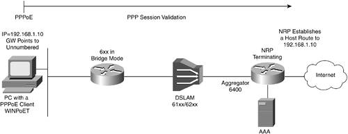
PPPoEPPPoE is becoming the technology of choice for new DSL installations. It enables providers to conserve IP addresses and use them per connection, and to track the IP address to a specific client. RFC 2516 provides the standard for communicating through PPPoE. With PPPoE, an ADSL modem acts as an Ethernet-to-wide-area network (WAN) bridge. The PPP network parameters are negotiated and the PPP session is established between the CPE and the LAC or NRP. CPEs that can negotiate PPP parameters and terminate the session include both a host and router. Any host with PPP client software such as RASPPPoE, NTS EnterNet or Windows PPP over Ethernet Client Software Application (WINPoET), can perform this function. A router such as the Cisco 806 dual Ethernet router that sits behind an ADSL modem, or the Cisco 827 that incorporates the ADSL modem and establishes the PPP session, are examples of typical small office/home office (SOHO) CPEs that can handle all facets of the PPP session. The CPE starts a PPP session by encapsulating PPP frames into a Media Access Control (MAC) frame, then bridging the frame (over Asynchronous Transfer Mode [ATM]/DSL) to the LAC or NRP. As a result, PPP sessions can be established, authenticated, and addressed. The client receives its IP address using IP Control Protocol (IPCP) from the PPP termination point, or the LAC or NRP. An example of a DSL implementation that uses a PPPoE network architecture is shown in Figure 21-8.[8] Figure 21-8. PPPoE over ADSL Architecture Example
PPPoE StagesAs specified in RFC 2516, PPPoE has two distinct stages, the discovery stage and the PPP session stage. When a host wants to start a PPPoE session, it must first perform discovery to identify which server can meet this client's request, then identify the Ethernet MAC address of the peer and establish a PPPoE SESSION_ID. Although PPP defines a peer-to-peer relation-ship, discovery is inherently a client-server relationship. In the discovery process, a host (the client) discovers an access concentrator (AC) (the server). Based on the network topology, more than one AC can communicate with the host. The discovery stage allows the host to discover all ACs and then select one. When discovery is successfully completed, both the host and the selected AC have the information they need to build a point-to-point connection over Ethernet. After a PPP session is established, both the host and the AC must allocate the resources for a PPP virtual interface; however, this might not be the case for all implementations. Finally, to be in compliance with RFC 2516, the IP MTU must be specified as 1492 for PPPoE. PPPoE Discovery StageThe discovery stage consists of four steps:
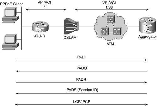
When the host receives the confirmation packet, it proceeds to the PPP session stage, and when the AC sends the confirmation packet, it proceeds to the PPP session stage. At the completion of the discovery stage, both peers know the PPPoE SESSION_ID and the peer's Ethernet address, which together define the PPPoE session uniquely. The host sends the PPPoE Active Discovery Initiation (PADI) packet with the DESTINATION_ADDR set to the broadcast address. The PADI consists of one tag, indicating what service type it is requesting. When the AC receives a PADI that it can serve, it replies by sending a PPPoE Active Discovery Offer (PADO) packet. The DESTINATION_ADDR is the unicast address of the host that sent the PADI. If the AC cannot serve the PADI, it must not respond with a PADO. Because the PADI was broadcast, the host can receive more than one PADO. The host reviews the PADO packets it receives and chooses one. The choice can be based on the services offered by each AC. The host then sends one PPPoE Active Discovery Request (PADR) packet to the AC that it has chosen. The DESTINATION_ADDR field is set to the unicast Ethernet address of the AC, or the router that sent the PADO. When the AC receives a PADR packet, it prepares to begin a PPP session. It generates a unique SESSION_ID for the PPPoE session, and replies to the host with a PPPoE Active Discovery Session-confirmation (PADS) packet. The DESTINATION_ADDR field is the unicast Ethernet address of the host that sent the PADR. The PPPoE negotiation process is shown in Figure 21-9. Figure 21-9. Negotiation Process for a PPPoE Client
PPPoE Session StageAfter the PPPoE session begins, PPP data is sent as in any other PPP encapsulation. The typical number of steps per exchange in the PPPoe session stage is four steps for link control protocol (LCP), two or four steps for AUTH, and a various number of steps for Network Control Protocol (NCP), it is dependent on the Layer 3 protocols that are in use. At this point, all Ethernet packets are unicast. A PPPoE Active Discovery Terminate (PADT) packet can be sent anytime after a session is established, to indicate that a PPPoE session has been terminated. The packet can be sent by the host or the AC. The DESTINATION_ADDR field is a unicast Ethernet address. PPPoE Discovery and Session NegotiationThe Cisco 827 router provides an excellent illustration of PPPoE negotiations. The output from the router is shown in Example 21-23. For this example, IOS v12.2(2)XH is used and the following debug commands are activated:
Example 21-23 shows the output as a result of debugging the dialer events, ATM events, VPDN events, PPPoE events, and PPP packets for a Cisco 827 router. Example 21-23. Output from a Cisco 827 Router Showing Successful PPPoE Discovery Stage NegotiationVPN-dsl#show debug Dial on demand: Dial on demand events debugging is on Generic ATM: ATM events debugging is on VPN: VPDN events debugging is on PPPoE protocol events debugging is on PPP: PPP packet display debugging is on *Oct 18 16:02:18 PST: Sending PADI: vc=0/35 ! The router sends its PAD initiation (PADI). *Oct 18 16:02:18 PST: padi timer expired *Oct 18 16:02:18 PST: PPPoE 0: I PADO L:0004.27fd.970e R:0010.6700.b5a0 0/35 AT0 ! The router receives the LAC response with the PAD offer (PADO), ! with L: and R: over vc/vp 0/35 ATM0. ! I indicates input, L for local, and R is remote. ! The number strings following these letters are MAC addresses of ! the respective host. *Oct 18 16:02:20 PST: PPPOE: we've got our pado and the pado timer went off *Oct 18 16:02:20 PST: OUT PADR from PPPoE tunnel ! The router sends PAD request (PADR) out. *Oct 18 16:02:20 PST: PPPoE 4922: I PADS L:0004.27fd.970e R:0010.6700.b5a0 0/35 AT0 *Oct 18 16:02:20 PST: IN PADS from PPPoE tunnel ! The router receives the PAD session confirmation (PADS). ! The discovery stage is done. *Oct 18 16:02:20 PST: %DIALER-6-BIND: Interface Vi1 bound to profile Di1 ! The virtual interface is created and referred to as Vix ! (in this example, replace x with 1). ! It bonds to the dialer interface to start the PPP Session stage. *Oct 18 16:02:20 PST: PPPoE: Virtual Access interface obtained. At this point, the router and AC complete the PPPoE discovery stage. If you enter the command show ip interface brief, you see that a virtual-interface has been established, as shown in Example 21-24. Example 21-24. IP Interface Status After PPPoE Discovery Stage VPN-dsl#show ip interface brief Interface IP-Address OK? Method Status Protocol ATM0 unassigned YES NVRAM up up Dialer1 unassigned YES NVRAM up up Ethernet0 10.10.10.1 YES NVRAM up down Virtual-Access1 unassigned YES unset up up If, for some reason, the router cannot successfully negotiate the first steps in the discovery stage, you might see output similar to that shown in Example 21-25. Example 21-25. Output from a Cisco 827 Router for a PPPoE Session Negotiation with a Failed Result*Oct 18 16:04:38 PST: Sending PADI: vc=0/35 *Oct 18 16:04:38 PST: pppoe_send_padi failed *Oct 18 16:04:38 PST: padi timer expired *Oct 18 16:04:40 PST: Sending PADI: vc=0/35 *Oct 18 16:04:40 PST: pppoe_send_padi failed *Oct 18 16:04:40 PST: padi timer expired *Oct 18 16:04:42 PST: Sending PADI: vc=0/35 *Oct 18 16:04:42 PST: pppoe_send_padi failed *Oct 18 16:04:42 PST: padi timer expired Next, you can see the output for the successful negotiation of the PPPoE session stage parameters, as shown in Example 21-26. Example 21-26. Output from a Cisco 827 Router for Successful PPPoE Negotiation*Oct 18 16:02:20 PST: Vi1 VPDN: Bind interface direction=2 *Oct 18 16:02:20 PST: Vi1 LCP: O CONFREQ [Closed] id 1 len 10 *Oct 18 16:02:20 PST: Vi1 LCP: MagicNumber 0x042A23C5 (0x0506042A23C5) *Oct 18 16:02:20 PST: %LINK-3-UPDOWN: Interface Virtual-Access1, changed state to up *Oct 18 16:02:20 PST: Vi1 DDR: Dialer statechange to up *Oct 18 16:02:20 PST: Vi1 PPP: I pkt type 0xC021, datagramsize 20 *Oct 18 16:02:20 PST: Vi1 PPP: I pkt type 0xC021, datagramsize 12 *Oct 18 16:02:20 PST: Vi1 LCP: I CONFREQ [REQsent] id 241 len 18 *Oct 18 16:02:20 PST: Vi1 LCP: MRU 1492 (0x010405D4) *Oct 18 16:02:20 PST: Vi1 LCP: AuthProto PAP (0x0304C023) *Oct 18 16:02:20 PST: Vi1 LCP: MagicNumber 0x02511B20 (0x050602511B20) *Oct 18 16:02:20 PST: Vi1 LCP: O CONFNAK [REQsent] id 241 len 8 ! The CPE refuses *Oct 18 16:02:20 PST: Vi1 LCP: MRU 1500 (0x010405DC) *Oct 18 16:02:20 PST: Vi1 LCP: I CONFACK [REQsent] id 1 len 10 *Oct 18 16:02:20 PST: Vi1 LCP: MagicNumber 0x042A23C5 (0x0506042A23C5) *Oct 18 16:02:20 PST: Vi1 PPP: I pkt type 0xC021, datagramsize 20 *Oct 18 16:02:20 PST: Vi1 LCP: I CONFREQ [ACKrcvd] id 242 len 18 *Oct 18 16:02:20 PST: Vi1 LCP: MRU 1492 (0x010405D4) *Oct 18 16:02:20 PST: Vi1 LCP: AuthProto PAP (0x0304C023) *Oct 18 16:02:20 PST: Vi1 LCP: MagicNumber 0x02511B20 (0x050602511B20) *Oct 18 16:02:20 PST: Vi1 LCP: O CONFNAK [ACKrcvd] id 242 len 8 ! CPE refuses again *Oct 18 16:02:20 PST: Vi1 LCP: MRU 1500 (0x010405DC) *Oct 18 16:02:20 PST: Vi1 PPP: I pkt type 0xC021, datagramsize 20 ! Finally, the CPE agrees. *Oct 18 16:02:20 PST: Vi1 PPP: I pkt type 0xC021, datagramsize 16 *Oct 18 16:02:20 PST: Vi1 LCP: I CONFREQ [ACKrcvd] id 247 len 14 *Oct 18 16:02:20 PST: Vi1 LCP: AuthProto PAP (0x0304C023) *Oct 18 16:02:20 PST: Vi1 LCP: MagicNumber 0x02511B20 (0x050602511B20) *Oct 18 16:02:20 PST: Vi1 LCP: O CONFACK [ACKrcvd] id 247 len 14 *Oct 18 16:02:20 PST: Vi1 LCP: AuthProto PAP (0x0304C023) *Oct 18 16:02:20 PST: Vi1 LCP: MagicNumber 0x02511B20 (0x050602511B20) *Oct 18 16:02:20 PST: Vi1 PAP: O AUTH-REQ id 1 len 40 from VPN-dsl@xyz.net ! CPE starts the AUTH process with a request. *Oct 18 16:02:22 PST: Vi1 PPP: I pkt type 0xC023, datagramsize 7 *Oct 18 16:02:22 PST: Vi1 PPP: I pkt type 0xC021, datagramsize 10 *Oct 18 16:02:22 PST: Vi1 LCP: I ECHOREQ [Open] id 0 len 8 magic 0x02511B20 *Oct 18 16:02:22 PST: Vi1 LCP: O ECHOREP [Open] id 0 len 8 magic 0x042A23C5 *Oct 18 16:02:22 PST: Vi1 PPP: I pkt type 0x8021, datagramsize 12 *Oct 18 16:02:22 PST: Vi1 PAP: I AUTH-ACK id 1 len 5 ! Access Concentrator agrees on PAP AUTH. *Oct 18 16:02:22 PST: Vi1 IPCP: I CONFREQ [Closed] id 241 len 10 *Oct 18 16:02:22 PST: Vi1 IPCP: Address 64.175.247.254 (0x030640AFF7FE) *Oct 18 16:02:22 PST: Vi1 IPCP: O CONFREQ [Closed] id 1 len 22 *Oct 18 16:02:22 PST: Vi1 IPCP: Address 0.0.0.0 (0x030600000000) *Oct 18 16:02:22 PST: Vi1 IPCP: PrimaryDNS 0.0.0.0 (0x810600000000) *Oct 18 16:02:22 PST: Vi1 IPCP: SecondaryDNS 0.0.0.0 (0x830600000000) *Oct 18 16:02:22 PST: Vi1 PPP: I pkt type 0x8021, datagramsize 24 *Oct 18 16:02:22 PST: Vi1 IPCP: I CONFNAK [REQsent] id 1 len 22 *Oct 18 16:02:22 PST: Vi1 IPCP: Address 64.175.245.47 (0x030640AFF52F) *Oct 18 16:02:22 PST: Vi1 IPCP: PrimaryDNS 63.203.35.55 (0x81063FCB2337) *Oct 18 16:02:22 PST: Vi1 IPCP: SecondaryDNS 206.13.28.12 (0x8306CE0D1C0C) *Oct 18 16:02:22 PST: Vi1 IPCP: O CONFREQ [REQsent] id 2 len 22 *Oct 18 16:02:22 PST: Vi1 IPCP: Address 64.175.245.47 (0x030640AFF52F) *Oct 18 16:02:22 PST: Vi1 IPCP: PrimaryDNS 63.203.35.55 (0x81063FCB2337) *Oct 18 16:02:22 PST: Vi1 IPCP: SecondaryDNS 206.13.28.12 (0x8306CE0D1C0C) *Oct 18 16:02:22 PST: Vi1 PPP: I pkt type 0x8021, datagramsize 24 *Oct 18 16:02:22 PST: Vi1 IPCP: I CONFACK [REQsent] id 2 len 22 *Oct 18 16:02:22 PST: Vi1 IPCP: Address 64.175.245.47 (0x030640AFF52F) *Oct 18 16:02:22 PST: Vi1 IPCP: PrimaryDNS 63.203.35.55 (0x81063FCB2337) *Oct 18 16:02:22 PST: Vi1 IPCP: SecondaryDNS 206.13.28.12 (0x8306CE0D1C0C) *Oct 18 16:02:23 PST: %LINEPROTO-5-UPDOWN: Line protocol on Interface Virtual-Access1, changed state to up ! Virtual interface protocol is up and it is in the IPCP phase. *Oct 18 16:02:24 PST: Vi1 IPCP: TIMEout: State ACKrcvd *Oct 18 16:02:24 PST: Vi1 IPCP: O CONFREQ [ACKrcvd] id 3 len 22 *Oct 18 16:02:24 PST: Vi1 IPCP: Address 64.175.245.47 (0x030640AFF52F) *Oct 18 16:02:24 PST: Vi1 IPCP: PrimaryDNS 63.203.35.55 (0x81063FCB2337) *Oct 18 16:02:24 PST: Vi1 IPCP: SecondaryDNS 206.13.28.12 (0x8306CE0D1C0C) *Oct 18 16:02:24 PST: Vi1 PPP: I pkt type 0x8021, datagramsize 24 *Oct 18 16:02:24 PST: Vi1 IPCP: I CONFACK [REQsent] id 3 len 22 ! The IP address 64.175.245.47 is assigned to Dialer 1 *Oct 18 16:02:24 PST: Vi1 IPCP: Address 64.175.245.47 (0x030640AFF52F) *Oct 18 16:02:24 PST: Vi1 IPCP: PrimaryDNS 63.203.35.55 (0x81063FCB2337) *Oct 18 16:02:24 PST: Vi1 IPCP: SecondaryDNS 206.13.28.12 (0x8306CE0D1C0C) *Oct 18 16:02:25 PST: Vi1 PPP: I pkt type 0x8021, datagramsize 12 *Oct 18 16:02:25 PST: Vi1 IPCP: I CONFREQ [ACKrcvd] id 241 len 10 *Oct 18 16:02:25 PST: Vi1 IPCP: Address 64.175.247.254 (0x030640AFF7FE) *Oct 18 16:02:25 PST: Vi1 IPCP: O CONFACK [ACKrcvd] id 241 len 10 *Oct 18 16:02:25 PST: Vi1 IPCP: Address 64.175.247.254 (0x030640AFF7FE) *Oct 18 16:02:25 PST: Vi1 DDR: dialer protocol up *Oct 18 16:02:25 PST: Vi1 PPP: I pkt type 0xC021, datagramsize 10 At this point, the virtual interface is now assigned an IP address, as shown in Example 21-27, and data transfer can be started. Example 21-27. IP Interface Status after Completing PPPoE Session Stage Negotiation VPN-dsl#sh ip int brie Interface IP-Address OK? Method Status Protocol ATM0 unassigned YES NVRAM up up Dialer1 64.175.245.47 YES IPCP up up Ethernet0 10.10.10.1 YES NVRAM up down Virtual-Access1 unassigned YES unset up up Common Issues for Remote Access VPNs with PPPoE on ADSLTwo of the more common issues that ADSL PPPoE clients encounter are authentication into the provider's network, and the MTU of the PPPoE adapter. Clients can choose to use a router or a SW application on their host to negotiate both the authentication and MTU parameters. In almost all cases, the remote access device must be configured to provide a PPPoE username and password to authenticate with the provider's authentication server. If the client or router cannot negotiate an IP address with the provider, confirm that the PPPoE username and password are correct. If they are correct and you still cannot obtain an IP address, verify the network infrastructure at home. If using a router to negotiate authentication, switch to a host and use one of the SW PPPoE adapters. If you still cannot negotiate an address, you might have to work with the provider to verify that the service is operational and that you have the correct authentication parameters. In Chapter 22, "Remote AccessVPN Troubleshooting Scenarios," a scenario is presented that shows the steps required to change the MTU on some SW PPPoE adapters. Some routers, such as the Cisco827, also provide this feature. VPN and Internet Access Through a Cable TV InfrastructureIn the last few years, Multiple Service Operators (MSOs) have been upgrading their networks and installing high-speed data communication systems that operate over the cable television (CATV) system to provide Internet broadband connectivity to subscribers. These systems effectively provide a data communications path that is transparent to IP over the last portion of their network. However, exchanging TCP/IP information over the Internet through a CATV network presents it own unique issues and challenges to remote access VPNs, which are addressed in the next section. Subsequent sections related to this topic cover the following:
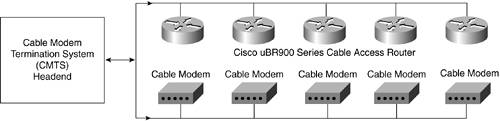
Overview of Data Transmission over a CATV NetworkCATV networks were originally designed and used for one-way distribution of analog television signals, from the operator to the subscriber. Under this configuration, a substantial amount of bandwidth on the CATV infrastructure was unused. By upgrading a portion of the CATV system to fiber optics, it is usually possible to enable signal flow in both directions. Most CATV networks that support two-way data distribution are hybrid fiber-coaxial (HFC) networks. The signals run in fiber-optic cables from the headend center, to node locations near the subscriber. From these nodes, the signal is converted from fiber to coaxial cables that run to the subscribers' premises. Higher frequencies flow toward the subscriber, and the lower frequencies travel in the opposite direction. Cable Modems and Cable InfrastructureThe term cable modem refers to a modem that operates over ordinary CATV networks. Basically, the subscriber connects the cable modem to the outlet for the TV, and the MSO or CATV operator connects a cable modem termination system (CMTS) at their end, commonly known as the head-end, as shown in Figure 21-10. The CMTS supports the data exchange. Normally, a single channel on a CMTS supports approximately 2000 simultaneous cable modem users. If more cable modems are required, additional channels must be added to the CMTS. Figure 21-10. High-Level Graphical Representation of a CMTS and Cable Modem Architecture
Almost all cable modems are standalone units with Ethernet interfaces; however, some are available that can be installed internally in a host, or that provide a USB port. The term cable modem is somewhat misleading, as you recall experiences with analog or ISDN modems. A cable modem provides a LAN interface and behaves similarly to other network devices. However, cable modems do display some operating characteristics that are similar to traditional modems. Normal operating ranges can be over 100 km, and the typical data throughput of most modems is 3 to 50 Mbps. The modems can act either as MAC layer bridges or as routers. Major differences between analog and ISDN modems are the online status and speed. Cable modems are online whenever they are powered-up and connected to the cable plant. Cable modems are much faster than conventional telephony modems, which are capable of speeds 25 to 1000 times faster. Remember that this is the speed the subscriber experiences between the modem and the operator's CMTS. Actual performance for a host browsing the web varies based on a number of factors with varying levels of influence. Some of the more common dependencies include the number of cable modems on the segment, the speed of the connection between the operator's network and the Internet, and the deployment and effectiveness of proxy cache servers. Standards for Data Transmission over CableUnfortunately, there is no one industry-wide standard that covers the transmission of data over cable networks. In North America, the Data-Over-Cable Service Interface Specifications (DOCSIS) addresses cable modems and CMTS. DOCSIS was initiated by a consortium of MSOs and has the support of major cable modem manufacturers and network operators. There is an ongoing battle in Europe between the initial DVB/DAVIC and EuroDOCSIS standards. For the purposes of brevity, the DOCSIS standard is discussed in more detail, and any differences between it and the EuroDOCSIS or DVB/DAVIC standards are noted. The new DOCSIS 1.1 specification is built upon DOCSIS 1.0 (www.cablemodem.com), but differs from it with the following features:
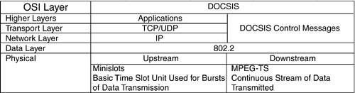
The emerging DOCSIS 2.0 (in development since late 1998) delivers all the capabilities of DOCSIS 1.1, and by providing greater resilience to noise, DOCSIS 2.0 provides more reliable and efficient service delivery. DOCSIS 2.0 is not only compatible with previous versions of DOCSIS, but allows improved performance of 1.0 and 1.1 modems when DOCSIS 2.0 modems and CMTSs are deployed on the network. DOCSIS 2.0 adds throughput in the upstream portion of the cable plantfrom the consumer out to the Internetwhich creates a network that has 30-Mbps capacity in two directions. That tripling of data capacity enables services such as videoconferencing and peer-to-peer applications. DOCSIS 2.0 enables operators to create new services for both home and business use, including symmetrical and critical applications. The modulation techniques for DOCSIS 2.0 include synchronous code division multiple access (S-CDMA) and advanced frequency agile time division multiple access (A-TDMA). Further discussion about VPN over cable is based on the most commonly deployed solutions todayDOCSIS 1.0. Cable System Architectural ElementsThe cable modem typically is connected to a two-way cable RF path over a low-split HFC cable system. In the downstream direction, the cable modem receives signals in a predefined portion of the downstream passband, usually between 50 MHz and a system-dependent upper limit that can be 750 MHz or more. In the upstream direction, or away from the subscriber, the cable modem transmits signals in a predefined portion of the upstream passband, which is between 5 and 42 MHz. Similar to an Ethernet segment, data sent downstream from the CMTS is received by all cable modems on the CMTS channel segment. However, the various data over cable implementations are significantly more efficient with their bandwidth than Ethernet. Intended recipients can be one, some, or all cable modems on the segment. DOCSIS CharacteristicsThe Open System Interconnection (OSI) model for the operator interface of a DOCSIS cable modem is shown in Figure 21-11. Figure 21-11. The OSI Model as Applied to the DOCSIS Industry Standard
Physical characteristics of the downstream data are listed in Table 21-10.
Physical characteristics of the upstream data are listed in Table 21-11.
NOTE In Figures 21-9 and 21-10, there is 12 Mhz between the upstream and the downstream bands. This band is known as the guard band. One downstream channel is normally paired with a number of upstream channels to achieve the balance in required bandwidth. Each modem transmits bursts in time slots that are marked as reserved, contention, or ranging by the CMTS per a vendor-specific algorithm. Characteristics of the CMTS timeslots are highlighted in Table 21-12.
Common Issues for Remote Access VPNs over CATV Data NetworksThere are a limited number of issues to troubleshoot when running VPN over CATV data networks. Two common situations you might encounter when working on remote access VPNs, using the Cisco VPN Unity client over CATV networks, are two-way Internet connections and heartbeats that monitor the CPE. Two-Way Internet ConnectionsTwo-way Internet connections can be implemented by using either an analog modem integrated in the cable modem (a telephone return cable modem), or a modem on the PC host. In the latter configuration, you normally cannot pass data over a VPN IPSec tunnel. This is because the Ethernet and dial interfaces on the PC have different IP addresses, and to successfully pass data with the Cisco VPN 3000 concentrator, the client must present one address. The former configuration, with the analog modem integrated into the cable modem, allows a Cisco VPN Unity client to pass data over the IPSec connection because the client is aware of only one routable address from the cable modem. HeartbeatsMost clients that are attached to CATV Internet connections obtain their routable IP address from the operator through DHCP. Some operators then monitor the status of the CPE device that obtained the IP address through the use of a regular ping. If the CPE device fails to respond to the pings after a predetermined time interval, the operator assumes that the CPE device is no longer connected to the operator's network, and returns the IP address to the DHCP pool. If the CPE device that obtains the IP address is the host that terminates the VPN tunnel, and if split tunneling is not enabled, the CPE does not respond to the pings sent from the operator to the public IP address. The reason for non-response is because the CPE device is assigned an IP address from the concentrator for the duration that the IPSec VPN tunnel is active, and it only responds to IP traffic that is received over the IPSec tunnel. A work-around for this scenario is to use a router to obtain the IP address from the operator, and to configure the router to NAT the host with the VPN client. Select a concentrator and profile that supports IPSec over UDP encapsulation. The router then responds to the operator's pings and you can establish and exchange data over the IPSec tunnel. VPN and Internet Access over Satellite and Wireless SystemsSatellite and wireless-based communication systems deliver Internet connectivity to users who otherwise do not qualify for typical SOHO and residential broadband solutions, such as DSL and CATV. However, because of their inherent designs and features, IPSec VPNs face unique issues when operated over satellite and wireless solutions. In particular, you learn about the following:
Satellite and Wireless Systems SpecificsCurrent Satellite (DBS) systems, such as Starband or Directway, are being deployed in greater numbers to provide Internet access. DBS systems are capable of delivering one-way downstream data rates of 23 Mbps or more; however, they do introduce error rates of 12 percent (www.internettrafficreport.com). Also, they inherently increase the latency that users experience by a minimum of several hundred milliseconds. An inherent delay occurs in the delivery of messages over a satellite link because of the finite speed of light and the altitude of communications satellites. Therefore, the propagation time for a radio signal to travel twice that distance (corresponding to a ground station directly below the satellite) is 239.6 milliseconds (ms) (see RFC 2488). The propagation delay for a message and the corresponding reply (one round-trip time [RTT]) is at least 558 ms. The RTT is not based solely on satellite propagation time; it is increased by other network factors, such as transmission time and propagation time of other links in the network path, and queuing delay in gateways that have terrestrial components. Typically, satellite RTT is 560 ms and the terrestrial side is about 150 ms; hence, the total RTT for the TCP connection is 710 ms (see the following Note). As a result, today's offering can achieve download speeds in the range of 500 kbps to 1 Mbps and upload speeds approaching 128 kbps. Satellite channels are dominated by two fundamental characteristics for noise and bandwidth that are described in subsequent sections of this chapter. NOTE Measurements show that the error level is slightly higher. Pchar output follows from a satellite connection, demonstrating 68 percent error loss that varies between day and night, and approximately 0.8s one-way RTT: ....XXX.78.249.254 (misc-XXX-78-249-254.pool.starband.net) Partial loss: 12 / 138 (8%) Partial char: rtt = 813.546203 ms, (b = 0.189682 ms/B), r2 = 0.149781 stddev rtt = 99.374317, stddev b = 0.070578 Partial queueing: avg = 0.369341 ms (133278 bytes) Hop char: rtt = 739.066865 ms, bw = 42.346064 Kbps Hop queueing: avg = 0.362248 ms (1917 bytes) The text discusses each of the following issues in detail in the subsequent sections:
Noise and Satellite and Wireless SystemsThe strength of a radio signal falls in proportion to the square of the distance traveled. For a satellite link, the distance is great and the signal weakens before reaching its destination. This results in a low signal-to-noise ratio (SNR) and increased error rate. Typical error control coding, such as Reed Solomon, can be added to existing satellite services and is currently being used by many other services. Bandwidth and Satellite and Wireless SystemsThe radio spectrum is controlled by licenses and the typical carrier frequencies for current, point-to-point, commercial, satellite services are 6 GHz (uplink) and 4 GHz (downlink), also known as C band, and 14/12 GHz (Ku band). From the point of view of VPN over wireless, existing wireless systems (see Chapter 3, "The Cloud," for more details) offer a different spectrum of challenges. Wireless systems typically have higher bit error rates (BERs) than wire-based carriage systems. Mobile wireless systems also include factors such as signal fade, base-station handover, and variable levels of load. The noise and bandwidth characteristics also apply, but the most important point is the affect both systems have over VPN. More information on this topic is included in the Performance Implications of Link Characteristics (PILC) Group of the Internet Engineering Task Force (IETF) through www.ietf.org/internet-drafts/draft-ietf-pilc-2.5g3g-07.txt. VPN, TCP, and TCP Inefficiency over Satellite and Wireless SystemsIPSec is an IP-based set of protocols, which interacts with the TCP/IP stack. As stated in Chapter 19, the tunnel mode of VPN essentially uses protocols, such as AH and ESP, to encapsulate the IP packets. TCP is also involved because some of the calculations and headers involve TCP headers (see Figure 21-5). A problem exists when you run VPN over high-latency networks, such as satellite and wireless, where the throughput degrades significantly compared to VPN over wire-based technologies. What seems to be the problem? TCP was designed using wire-based assumptions that include the following:
The full description of TCP assumptions and inefficiencies are available in RFC 2488 and RFC 2760. You can also see RFC 1323. If these assumptions are challenged, the associated cost is TCP efficiency. If TCP is extended to environments where these assumptions are no longer valid, preserving the integrity of the TCP transfer and maintaining a high level of efficiency can require the TCP operation to be altered. Overall, because satellite and wireless channels have several characteristics that differ from most terrestrial channels, they can degrade TCP performance. TCP Characteristics That Impact PerformanceMany characteristics can impact performance:
Performance Solutions in Satellite NetworksAs explained, TCP was specifically designed as a flexible protocol that operates on various wired networks. However, it is not optimal for wireless or satellite links, and it proves to be a medium where TCP provides marginal service. Because latency is a constant concern of enterprise VPNs, but enterprise VPNs are not the main concern of satellite providers, the only viable option is to increase the throughput, implementing proprietary solutions to improve or resolve issues introduced by using TCP over satellite networks. To help you understand the nuances of some of the implemented proprietary solutions, the discussion is further divided into the following sections:
Manipulating (Tweaking) the TCP StackOne possible solution to improve performance is explained in Chapter 3, and is based on the Internet Page Accelerator (IPA), which allows increased numbers of concurrent HTTP 1.0 and 1.1 sessions. Another possible solution is tweaking the TCP protocol. Some aspects of this approach are described in RFC 2488. The suggested summary of the recommendations is shown in Table 21-13. FEC stands for forward error correction, PAWS stands for Protection Against Wrapped Sequence Space, and RTTM is Round-Trip Time Measurements. NOTE Cisco IOS version 12.2+ allows some functions to be performed on the router's TCP traffic, such as ip tcp timestamp or debug ip tcp sack. RFC 1323 timestamps help TCP to measure RTT accurately to adjust retransmission timeouts. By default, they are disabled in Windows and are considered ineffective. The ip tcp timestamp works with another technique called window scaling, which permits TCP to negotiate a scaling factor for the TCP receive window size. It permits a large TCP receive window of up to 1 GB. This option must be enabled if you want to use receive windows larger than 64 KB. Window scaling is enabled by default in Windows.
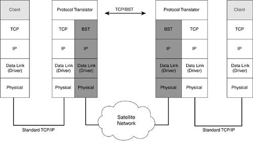
Numerous software solutions exist on the market, such as TweakMaster of Hagel Technologies, DrTCP, and others. The effect of these measures is moderate, and there is some reasonable improvement to the responsiveness of applications, even when running VPN, but tweaking techniques don't offer radical solutions for the degradation of speed when it comes to using VPN over wireless or satellite. Why? Because when it comes to an overall solution, according to Table 21-13, in some cases both ends, not only the sender, must perform some procedures. In the default TCP stack installations, this is definitely not the case. Boosted Session Transport ProtocolOne example of a different approach to TCP, related to performance issues, is the implementation of the Boosted Session Transport (BST) protocol (see www.flashnetworks.com/). BST is a connection-oriented protocol used instead of TCP on satellite or wireless segments. TCP traffic is converted to BST flows before being sent across the wireless WAN links, and then is converted back to TCP before being sent to the intended destination, as shown in Figure 21-12. BST is available in the NettGain product line from Flash Networks, and has been implemented in satellite networks by StarBand, NASA, SAT-TEL, and VSAT. Figure 21-12. The BST Mechanism
The BST protocol offers numerous enhancements over TCP:
The FITFEEL Transmission ProtocolAnother solution to the TCP performance problem was introduced by the authors of the Fast Information Transfer For Extremely Errored Links (FITFEEL) protocol, which introduces a simple transmission protocol that performs better than TCP over bad links. The basic assumption of using the TCP proxy concept is that TCP applications can be used effectively on poor links without alteration. This is accomplished by translating TCP to a better protocol over the problematic links, then translating back to TCP at the other end. The FITFEEL addresses aspects of TCP action when there is either a propagation delay, bit error, queuing delay, or buffer overflow. The TCP proxy concept is referred to as TCP boomerangs, and the boomerang effect is achieved with proxy software that talks TCP language to the initiating host in the role of the destination host, and so forth. Using this approach, the TCP boomerang trick reflects outgoing TCP packet streams to an IP host, which simply and reliably handles the TCP protocol by acting in the role of a proxy. IPSec VPN Performance Issues over Satellite SystemsBoth BST and FITFEEL protocols implement a proprietary form of compression. Given the fact that there is always a transformation of the TCP stack either to the BST stack, or to a proxy TCP, IPSec-based solutions experience significant degradation of the overall throughput. VPN performance over satellite systems can be disappointing, often limited to dialup speeds. However, a user can make some adjustments to their W2K host to improve performance, but it is significantly lower than the download speeds that users expect when not using VPN. It all depends on the perspective: either the IPSec VPN shows a significant degradation in throughput, or the IPSec VPN cannot take advantage of the boosting protocol mechanisms. Using traffic boosting protocols does not affect any of the transport layer security protocols, such as Secure Sockets Layer (SSL) or Transport Layer Security (TLS). This is because they do not modify the contents of the TCP payload. It is not known if boosting protocols pose any potential security risk to Layer 2 protocols, such as PPP, because it does not modify the IP information. On the other hand, they do replace the TCP headers with a new header over the wireless/satellite hop. As a result, potential security issues exist with IPSec because AH and ESP use the Integrity Check Value (ICV) for calculating much of the TCP header information. NOTE The Satellite Service Providers use two main strategies when it comes to erroneous packets: They either request repeat, apply error correction, or use both. The author experiments and measurements with Cisco VPNs over satellite show that Concatenated Viterbi and Reed Solomon error-correction codes, used by Spacenet, allow the users to achieve better performance. See www.spacenet.com/ for details. Possible resolutions include the following:
Information about the interaction of the FITFEEL protocol with IPSec-based VPN solutions was not available at the time this book was written; however, possible solutions are under study. Some of the issues are addressed in the VPN client versions 3.5.x and higher (NAT/UDP and NAT/TCP encapsulations and transparent tunneling), and some of them might become available with the newest Cisco content engines (CTE 1400 and COE 590). Check www.cisco.com regularly for updates. Another approach to this problem is checking if the satellite providers move to another coding technique where they don't need to boost the traffic. One possible solution in this direction is the emerging Ku-band technology, which essentially uses DOCSIS 1.1 for wireless broadband services. DOCSIS 1.1-based systems are expected to use Ku-band wireless broadband services with expected rates up to 10 Mbps and transmission rates up to 500 kbps. No known issues exist with IPSec-based VPNs and the DOCSIS 1.1 specification. | |||||||||||||||||||||||||||||||||||||||||||||||||||||||||||||||||||||||||||||||
EAN: 2147483647
Pages: 235