Remote Access VPN Design Solutions
| To clarify your need for a remote access VPN solution, you must first differentiate between remote access and site-to-site S2S VPNs, as shown in Table 20-1.
A remote access solution is required to meet the demands for mobility from sales or remote staff who are frequently out of the office. Individual remote users require access to resources on their organization's network, regardless of the fact that they might be at a fixed location or roaming by connecting through high-bandwidth services to the Internet. However, the distinction between remote access and smaller S2S VPN requirements is starting to blur because Cisco's product offerings in this area provide more flexibility. Today, remote access solutions provide not only Client mode, but also Network-Extension mode (VPN3002, Easy VPN, PIX 501 and 506), which enables a separate private network to be deployed on the client side with addressing that is routable with the organization's network. This expands the initial understanding of a S2S solution. For large-scale enterprise remote access VPNs, particularly those that must support broadband connections, the key objectives of the design phase of VPNs are as follows:
The most important decisions in the design phase of remote access VPN solutions include outlining the key objectives of the design, understanding how the VPN management processes are implemented, planning the required security policies, and knowing how to create a robust and scalable environment. Remote Access VPN Design ObjectivesTypically, a remote access VPN solution should meet the resiliency and availability standards of other areas of your network. Assuming that your organization has designed its Internet connectivity to provide local and global redundancy, you must consider product features that allow you to maximize service levels for your user base:
The management of VPN solutions is crucial not only to protect the company's resources from unauthorized access, but also to enable a transparent and manageable solution for all categories of potential users, including full-time telecommuters, day-extenders, road-warriors, and engineers who are working from home or from a customer's site. The solution deployed for each category must be evaluated according to the ability to deploy, change, and enforce policy from the central site. Remote Access VPN ManagementRobust VPN management is a crucial factor for any large remote access VPN deployment. The relevant management features can fit into three broad categories: configuration, change, and operations Configuration ManagementVPN is a sophisticated technology with an extensive number of configuration options. To fully realize the benefits, it must be easier to deploy than earlier solutions. Characteristics of strong configuration management include the following:
Change ManagementInevitably, you will make changes to your VPN implementation. This might be as simple as changing the Simple Network Management Protocol (SNMP) strings on your central equipment, to a complete upgrade of your central devices and clients. The following are examples of requirements to consider when determining your change management needs:
Operations ManagementDay-to-day monitoring and management of the VPN solution should be automated to the fullest extent, and require minimal human interaction to maintain service levels at the highest levels of operational availability. Examples of effective operations management include the following:
(See the section, "Redundancy" later in this chapter, which covers redundancy using Virtual Router Redundancy Protocol (VRRP) and load balancing.) Remote Access VPN Security ConsiderationsThis section covers some of the decision-making aspects when deciding on a remote access VPN solution. Most of these considerations are valid for any VPN design, but the main focus of this section is on remote access solutions. In particular, the text covers the following:
Some of the following information was presented in detail in Chapter 19, "VPN Technology Background." Its presence here is to show how the different choices and options can or cannot make a difference in the design phase of remote access VPNs. User Authentication InfrastructureIdeally, organizations want to use what they already have deployed and are comfortable supporting. This is especially obvious for organizations that have some type of infrastructure to support dialup services. Although relatively few organizations have implemented Public Key Infrastructure (PKI) or digital certificate authentication systems across the entire enterprise, often systems to support RADIUS, TACACS+, NT Domain, and token-based security servers are already in-place. The argument could be made to migrate to VPN and PKI at the same time, but a general recommendation is to migrate to each technology individually to minimize the amount of change for the support organization. IPSec Transport and Tunnel ModeIf you decide to implement IPSec, theoretically, you must also decide whether to implement Authentication Header (AH), or Encapsulation Security Protocol (ESP), or both. AH provides data integrity and data origin authentication. However, it does not hide the contents of its packets, so it cannot provide data confidentiality. ESP does encrypt the data, but it does not protect the new IP header. Ideally, you use both ESP and AH to gain the benefits of both. In reality, almost all remote access VPN deployments use only ESP. Whether the IPSec AH or ESP protocol is chosen, the second important decision is whether to use transport or tunnel mode. Transport mode is used when both endpoints support IPSec, as opposed to tunnel mode, where there can be a proxy-like device terminating the tunnel, and then sending traffic on to and from the central network. In transport mode, the AH or ESP header is placed after the original header, and only the payload of the IP packet is encrypted. The original packet headers are left intact, which allows network services, such as quality of service (QoS) to be implemented. Tunnel mode encapsulates the entire IP packet in either AH or ESP, adding a new header, and then the entire datagram is encrypted. Because of its proxy-like capability, tunnel mode is almost exclusively used for all remote access VPN environments. IPSec Data Authentication and EncryptionSecurity protocols must ensure that data transmissions are secure after the user is authenticated. This requires special tunneling protocols and encryption services because the remote user's information might be intercepted in transit, and modified by a third party without the knowledge of the user or the application. Packet contents can be inspected and modified, and source and destination addresses can be changed. TCP/IP originally did not offer any method to secure the data stream. Examples of the security protocols include generic routing encapsulation (GRE), Layer 2 Tunnel Protocol (L2TP), Point-to-Point Tunneling Protocol (PPTP), and IPSec. In some instances, combining security protocols can be a preferable solution, as offered in the Cisco Unified VPN offering that is available in IOS versions 12.0S and 12.2T. For example, second layer tunneling could be more beneficial in high-latency networks, which require special measures to enforce your security policies. Based upon the details covered in Chapter 19, it is generally agreed that IPSec offers the strongest combination of features for tunneling, message authentication, and confidentiality. A crucial component of authentication and encryption is the generation of keys used for each process. The key exchange between the devices in a remote access VPN session also identifies the participants. The Internet Key Exchange (IKE) (formerly [Internet Security Association and Key Management Protocol] ISAKMP/Oakley) is the recommended solution, and configurable options include the Diffie-Helman (DH) group to be used with a popular public key crypto algorithm. There are some indications that development of a new key exchange algorithm, Fast Key Exchange, is underway. Data authentication confirms that the data one receives is actually the data that the originator intended to send. As part of IPSec-based VPNs, Cisco recommends data authentication protocols that use keyed hash algorithms. For most remote access environments, the Message Digest 5 (MD5) algorithm is the preferred alternative; however, the Secure Hash Algorithm 1 (SHA-1) is recommended for router-based or S2S solutions. These protocols offer configuration features that simplify their implementation. Encryption converts the data into a coded form with a key that can only be understood if you have the key and understand the encoding algorithm. Otherwise, you cannot read the original data in the encrypted format. The more common encryption algorithms include the Data Encryption Standard (DES) and Triple-DES (3DES). A recently developed algorithm is the Advanced Encryption Standard (AES), which was approved as a Federal Information Processing Standard (FIPS) by the National Institute of Standards and Technology (NIST) at the end of 2001. Similar to the hashes discussed earlier in this section of this chapter, these data encryption algorithms usually offer configurable parameters. Challenges of NAT/PATEnvironments that use NAT or PAT present challenges for establishing, transmitting, and receiving data across IPSec tunnels. A one-to-one NAT translation occurs when there is an internal address that is mapped to a unique external address. Although not widely used, this form of NAT is used by organizations that want to hide the identity of the end client. A one-to-many NAT, or a PAT environment, consists of one external address that is mapped to many internal addresses. The router or firewall that performs the NAT or PAT maintains a translation table that identifies the external destination address with a unique identifier, such as the TCP or User Datagram Protocol (UDP) port numbers, and maps these port numbers to traffic transmitted to specific devices on the internal network. PAT is used extensively on residential and corporate networks, and enables the user to conserve address space and hide the identity of their clients. Unfortunately, the ESP protocol does not use the concept of ports. Also, information in the packet is encrypted and unavailable, so the translation device cannot obtain the internal addresses from the IPSec packet. As a result, ESP is typically incompatible with this form of NAT. IPSec over UDP: A Viable AlternativeAs a workaround to the NAT issue described earlier in this chapter, Cisco implemented a technique where the IPSec traffic is encapsulated in UDP traffic, on the VPN 3000 series concentrator. By encapsulating the packet in UDP, the NAT translation device can perform the standard port mapping technique to uniquely identify the source and destination traffic flows. Implementing UDP encapsulation requires additional overhead for each packet, but it is relatively small compared to average packet sizes. At this time, a standards-based approach to resolving IPSec over NAT implementations has not been agreed upon. In the meantime, the Cisco alternative of UDP encapsulation is an effective solution. IPSec over UDP on the Cisco VPN 3000 Concentrator and ClientsTo use IPSec over UDP encapsulation, the VPN 3000 Concentrator administrator must configure either the user or a group. If enabled for a specific user, tunnel negotiation between the client and the concentrator occurs automatically by using IKE. The setup includes the UDP port number and the actual requirement for IPSec over UDP. It is configurable on the Cisco VPN Unity Client, but the Cisco VPN 3002 HW client does not offer any configurable options, so the IPSec over UDP feature for these client types must be configured on the Cisco VPN 3000 Concentrator. As part of enabling the IPSec over UDP option, the core site concentrator must be accessible through the negotiated UDP port; then, data transmissions will be successful from a client behind a device that is performing NAT. If the remote user is behind a firewall, the user must ensure that the firewall rules permit the required traffic, which is necessary for establishing the tunnel over the specified UDP port. IPSec over TCPThe Cisco VPN 3000 Concentrator, VPN Unity Client, and VPN 3002 HW Client provide the option to encapsulate IPSec traffic in TCP datagrams, which was released in v3.5 of these products. To activate this feature, both the core concentrator and the client must be configured to enable IPSec over TCP on the same TCP port. The benefit of enabling this feature is primarily for clients who try to access the central concentrator, while behind a firewall that only permits outside exchanges of datagrams that are started by internal hosts on well known or specific ports. By encapsulating the traffic over, for example, port 443 (https), the initiator can be reasonably confident that the firewall will permit responses from the core concentrator. This precludes the need to request security changes to accommodate IPSec, ISAKMP or specific UDP port traffic. Split TunnelingThe split tunneling feature allows clients to simultaneously send and receive data across a VPN tunnel, while also communicating directly with resources on the Internet. Only traffic that is destined for or originating from hosts on the network that are terminating the VPN connection is encrypted and sent across the tunnel. All other IP traffic is sent outside of the VPN connection to hosts connected on the Internet unencrypted. An organization might find split tunneling beneficial because it reduces the central resources required to support a VPN environment, including ISP bandwidth, and through-put on the local-area network (LAN) and VPN tunnel terminating device. However, many organizations with strict security policies might find the risk of implementing split tunneling too great, and restrict its use. Concerns might arise as split tunneling could increase the likelihood that an intruder might break into the corporate network by hacking a member's host that is concurrently connected to both the Internet and the corporate network through the VPN. The argument is that the organization does not want to extend their firewall capabilities to the customer premises equipment (CPE) at the remote user's location, and deal with the administration. To possibly address some of these concerns, an integrated stateful firewall was incorporated into v3.5A of the Cisco VPN Unity Client, which can be activated when a VPN connection is attempted or active. With v3.5 the VPN 3000 Concentrator included a configurable option to require or warn connecting SW VPN clients that they must implement a specific SW firewall. Further, with v3.5.1, the concentrator can point to a central server that administers the firewall policy. Firewall FunctionalityFirewalls are designed to protect a network from outside traffic that is determined to be hostile to the organization. Some products provide an integrated solution for both the firewall and the VPN terminating device; however, before covering this in more detail, the following descriptions of firewall types are provided:
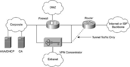
The concentrator rejects any traffic not sourced from one of the allowed protocols or ports. A common deployment for most organizations is to place a stateful inspection firewall in parallel with the VPN concentrator, which offers scaling advantages versus an integrated device. Another advantage of separate devices is the opportunity to implement management interfaces that are optimized independently for each environment. An obvious drawback of this solution is the fact that two different devices with different interfaces require support staff who are trained on both units. Remote Access VPN Termination Equipment Design ConsiderationsCisco recently developed the SAFE Blueprint,[1] which provides the latest information for VPN architecture and designs. An entire series of documents are available online from www.cisco.com. This information should be regularly reviewed to ensure that your networks incorporate the latest suggested designs and features. SAFE discusses various alternatives from the organization's perspective, taking into account the scale of the implementation, and the available resources of the organization. It is recommended that you extensively refer to this site when planning your remote access VPN offering. Termination Equipment Architecture GuidelinesA quick overview of some suggested items that should be considered for your VPN core device architecture are documented in this section. For remote access VPNs, determining the number of devices and where they are deployed is a major concern. To address location decisions, you must analyze your organization's firewall locations and determine where the largest numbers of your user community can access your network. Based on this analysis, enterprises usually provide VPN termination capability at these high-traffic Internet points of presence (POPs). For redundancy, clients can be automatically redirected to VPN core devices at other locations if they cannot access the devices in their chosen location. The number of VPN sites that you implement depends on your remote access strategy, Internet POPs, available bandwidth, and the availability of required support staff and procedures. In most cases, it is usually worthwhile to consolidate into selected sites, where bandwidth is plentiful and cost effective, to reduce the complexity of maintaining a large number of firewalls and demilitarized zone (DMZ) networks. However, this model might not be the best fit in areas of the world where there is little difference in the cost of Internet access versus dedicated bandwidth. Generally speaking, Cisco recommends that you install the VPN device in parallel with your corporate firewall in the DMZ, as shown in Figure 20-1. Figure 20-1. Cisco Recommended Architecture for VPN Core Devices
In the dotted-line configuration, only tunneled traffic is routed to the VPN concentrator from the Internet, and the concentrator is protected from denial of service (DOS) attacks. Alternatives are possible, such as placing a firewall behind and parallel to the concentrator to provide additional protection to the internal network from such things as virus-infected VPN clients. Numerous possibilities must be considered. It is recommended that you consult Cisco and network security specialists to determine the architecture that best meets your requirements. A number of questions can be considered in determining which core device to use as the core VPN tunnel terminating device:
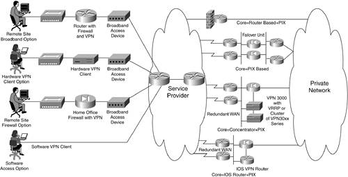
Core Device Choice ConsiderationsCisco IOS-based routers, PIX firewalls, and 3000 VPN Concentrators can all terminate remote access IPSec VPN tunnels (see Figure 20-2). The device(s) you select to implement depends on the scale of your roll out, the number of sites where remote access VPN tunnel terminating devices are located, and the available development and support resources within your organization. Figure 20-2. The Possible Combinations of Remote Access VPN Client and Termination Points
Where scalability is an issue, such as for medium and large-scale deployments with greater than 100 concurrent connections, dedicated devices for terminating the remote access VPN tunnels should be deployed. Generally speaking, for maximum security, the termination device should be in parallel with your corporate firewall. However, this extra security comes with slightly greater support costs because you must manage additional devices, versus a scenario where the terminating device was behind the firewall. Cisco Remote Access VPN Core DevicesThe device that you implement to terminate remote access IPSec VPN tunnels depends on the requirements and resources of the site and your organization. This section provides a brief overview of the Cisco VPN 3000 Series Concentrators. Additional information for the Cisco Easy VPN Server and PIX, as VPN tunnel terminating devices, is also provided. However, you should consult your Cisco resources to determine the latest information available about remote access VPN features in the IOS and PIX devices, and the use of these devices for terminating remote access VPN tunnels. Cisco VPN 3000 Series Concentrator FeaturesFunctions of the VPN 3000 Concentrator include the following:
The Cisco VPN 3000 Concentrators, in various models, address the remote access requirements of all organizations of any type and size. The available models and their specific features are listed in Table 20-2.[3] Configuration and selected features of the Cisco VPN 3000 Concentrators are covered in the following discussion.
Easy VPN ServerThe Easy VPN Server feature for Cisco routers was first offered in IOS Release 12.2(8)T. It allows a router to act as a VPN head-end device for remote access VPNs, where the remote device can be a Cisco Unity VPN Client, a VPN 3002 HW Client, a PIX501 or PIX506 running PIX OS v6.2 configured as a VPN client, or a Cisco 800 or 1700 series router configured with SW that supports the Easy VPN Client. Using the Easy VPN Server feature, security policies defined at the head-end can be pushed to the remote access client. The functions of the Easy VPN Server are similar to those of the Cisco VPN 3000 Series Concentrators. A list of the routers that function as an Easy VPN Server are as follows: Cisco 800, 1400, 1600, 1700, 2600, 3600, 7100, 7200, and 7500 series routers, and the uBR905 and uBR925 cable modems (see www.cisco.comunivercd/cc/td/doc/productsoftware/ios122/122newft/122t/122t8/ftunity.htm). A selected list of supported IPSec protocol options and attributes, supported by the Easy VPN Server, is listed in Table 20-3. A list of non-supported IPSec protocols and attributes is provided in Table 20-4. Detailed explanations of the attributes can be found in Chapter 19, or in the "Configuration of the VPN 3000 Concentrator" section.[4]
PIX 500 Series Firewalls as Remote Access VPN ServersPIX 500 series firewalls can also be configured as the core device that terminates remote access IPSec VPN tunnels. Concurrent users and throughput for the various PIX firewalls that are configured as core devices are shown in Table 20-5. The PIX firewalls support most of the same attributes as the Cisco Easy VPN Server with a few differences such as support for DH Group 1, but not for Group 5, which Easy VPN supports. Other selected features that PIX supports, but not the Easy VPN Server, are as follows:
One useful feature that is not supported on both the PIX and the Easy VPN Server is UDP encapsulation for NAT/PAT operating environments.
Performance Criteria for VPN Termination EquipmentThe device that terminates the VPN tunnel on the corporate network should be the solution that best meets the organization's requirements, while maximizing performance. As is often the case, the factors of cost, productivity, and security must be prioritized to assist with the selection of the most appropriate solution. Of course, financial concerns must be acknowledged, but these should be balanced against improved productivity and security. To evaluate the VPN termination device, compare your requirement's against the VPN device's capabilities. The device must authenticate users, based on centralized databases that are located on the concentrator, or through a proxy mechanism to central servers. It usually has two interfacesa public and private. As the names suggest, the public interface is accessible from the Internet or service provider network, and the private is protected by the corporate firewalls or by the concentrator itself. Encrypted traffic is passed through the public interface, and unencrypted traffic flows through the private interface. In most cases, performance is maximized by devices that are dedicated to terminating the VPN tunnel, instead of a shared-purpose device, such as a firewall. Specifications of the VPN termination equipment that should be carefully reviewed before making any commitments along with some recommendations include the following:
|
EAN: 2147483647
Pages: 235