Enterprise VPN Categories
| Every new technology requires some type of classification to distinguish it from a wide variety of solutions, proposals, and views. Cisco classifies the existing variety of VPN solutions into two main categories:
Functional VPN CategoriesThe three Cisco enterprise functional groups are remote access VPN, site-to-site VPN, and firewall-based VPN solutions. Each is discussed in the following sections. NOTE Each VPN classification has distinguishing features. Other valid classifications of VPNs are remote access VPNs, intranet VPNs, and extranet VPNs. As noted in the article, "SAFEguard for Smaller Networks" (Cisco Packet, Q1, 2002), Cisco SAFE categories include 800 series access routers, 1700 series modular routers, PIX firewalls, 3002 VPN Hardware Clients, the VPN Software Client, and the Intrusion Detection System (IDS). Remote Access VPNsRemote access VPNs refer to implementations for individual remote users that are running the VPN client software to access the corporate intranet through a gateway, or VPN concentrator, which is also referred to as a server. For this reason, this solution is often called a client/server solution, where telecommuters or mobile users can use traditional methods to start tunnels back to the corporation. These methods include dialup connections to a local service provider or the use of any high-speed or broadband service. The Cisco last-mile solution, called Ethernet to the First Mile (EFM) (see Cisco's 575 LRE customer premises equipment (CPE) and Cisco last-mile solutions in Chapter 3), when it becomes available, might change the way remote access VPNs are designed. Another relatively recent development in remote access VPNs is the wireless remote access VPN (see Cisco's Aironet product series), where a mobile worker accesses the corporate network through a wireless connection on a personal digital assistant (PDA). In this design, the wireless connection needs to connect to a wireless termination point and then to the corporate wired network at the remote location. In all cases, the client software on the PC or PDA provides a secure connection, referred to as a tunnel, back to the corporate network. An important part of this solution is the design of the initial authentication, which is designed to ensure a request to establish a tunnel from a trusted source. Usually, this initial phase relies on the same authentication security policies and remote access controls to access corporate resources, including procedures, techniques, and servers (such as Remote Authentication Dial-In User Service [RADIUS], Terminal Access Controller Access Control System Plus [TACACS+], and so on). Site-to-Site or LAN-to-LAN VPNSite-to-site or LAN-to-LAN VPN refers to implementations where the network of one location is connected to the network of another location through VPN. In this situation, the initial authentication process for trusted users is between devices on the network, where an initial VPN connection is established between them. These devices then act as gateways, securely passing traffic destined for the other site. Routers or firewalls with VPN capability, and dedicated VPN concentrators all provide this functionality. LAN-to-LAN VPNs can be considered as intranet or extranet VPNs, from the policy management point of view. If they are under one authority, it can be considered an intranet VPN; otherwise, they are considered as an extranet. Access between sites should be tightly controlled by both entities at their respective sites. The site-to-site solution is not a remote access solution, but was added here for completeness. The distinction between remote access VPNs and LAN-to-LAN VPNs is rather symbolic, and it is provided solely for the purposes of further discussion. One example is the new hardware-based VPN devices (see the Cisco 3002, described later), where this classification can be interpreted both ways because the hardware-based client can appear as if a single device is accessing the network, although there might be a network with several devices behind the VPN device. Another example includes the extension-mode of the EzVPN solution, by using 806 and 17xx routers. Firewall-Based VPNsFirewall-based VPNs are solutions where either the enterprise's security organization owns both the firewall and VPN implementation, or service providers offer enhanced firewall systems to support VPN services. In general, they are based on the Cisco PIX series firewalls, including the PIX 506 for small office, home office (SOHO) environments, the PIX 515 for small- to medium-sized businesses, and the PIX 525 and 535 for enterprise and service provider implementations. Cisco provides several remote access solutions for VPN clients. These solutions meet different enterprise requirements and are designed for each of the covered functional groups. These solutions include the following:
Another view of Cisco VPN solutions from a software-hardware point of view is as follows (for more details on what operating systems are supported, see www.cisco.com):
The introduction of the PIX 501 VPN solution expands the available choices for the remote user. The hardware options are further defined in Table 19-1. The full list of available VPN 3000 concentrator series products can be found under www.cisco.com/univercd/cc/td/doc/pcat/3000.htm#xtoc1d7.
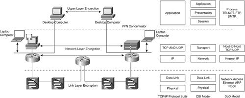
NOTE Recently, Cisco announced a comparative approach for classifying remote access VPNs that is based on key element ratings. The key elements are resiliency, scalability, client OS support, management, identity, and a consolidated solution. This classification is more suitable for practical purposes and better reflects the functional category. Technology CategoryFrom a technology perspective, VPN is not running special types of electrons over the shared switch or network, but it is running packets over networks, which are encrypted and authenticated in a way that distinguishes them from other packets. Often, this is associated with a tunnel in the network. Earlier solutions included the physical layer division of the circuits in the carrier's switches and main distribution frames (MDFs), which prevents unauthorized access between dedicated lines for separate enterprises, and creates a VPN. Later solutions included implementing the Secure Socket Layer (SSL) protocol for web browsers and other applications, which enables every application to be protected and provides application confidentiality. This is an encryption VPN solution that resides on the application layer of the Transmission Control Protocol/Internet Protocol (TCP/IP) suite. But in the OSI seven-layer model, the presentation layer is responsible for translation, encryption/decryption, authentication, and compression. To prevent confusion, it is most appropriate to refer to this solution as an upper-layer encryption (see Figure 19-3). Figure 19-3. The Layered Models and Encryption
For years, military implementations have used hardware-based link-layer encryption that addresses authentication concerns differently. Every termination of a communication link is protected with end devices. Although it ensures security protection, this solution is difficult to manage and almost impossible to implement in a large-scale public network. Data Link Layer VPNsIn the public network environment, data-link encryption can be implemented in devices within the private network; however, users must encrypt the traffic before it enters the router or switch. Obviously in this scenario, the traffic must be either bridged or encrypted/decrypted at every hop because the second layer does not provide a unique IP-type addressing scheme. As a result, the data (frames) needs to be encrypted/decrypted several times, which results in increased latency and concerns about trusted providers. ATM and Frame Relay networks are sometimes referred to as VPN networks because they use a shared infrastructure to provide private network services to a large number of users; however, they are viewed more as private network implementations. Data-link VPN technologies are designed to run on the second layer of the OSI model and include the following:
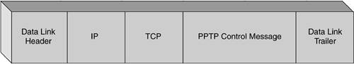
PPTP and GREPPTP is defined by the Internet Engineering Task Force (IETF) in RFC 2637.[3] It is designed by Microsoft to enable a low-cost, private connection to a corporate network through the public Internet. The PPTP session can provide a secure connection through the Internet to the corporate network when dialing a local ISP's phone number, or when using an ISDN device. The local call connects into a hardware device (front-end processor [FEP]), which in turn connects to a Windows NT Server through a WAN connection. The FEP connects by transmitting Point-to-Point Protocol (PPP) packets from the end user, and tunneling them through the WAN. Because PPTP supports multiple protocols (IP, Internetwork Packet Exchange [IPX], and Network Basic Input/Output System Extended User Interface [NetBEUI]), it can access a wide variety of existing LAN infrastructures. This architectural description includes a typical client/server architecture, where the client is the remote user's PC, running PPTP. On the server side, there is a dial-in router, VPN concentrator, or actual application server. Both sides can start a tunnel. When the remote user starts the tunnel, it is called voluntary mode. When the tunnel is started by the network access server (NAS), it is often referred to as compulsory mode. A NAS can start a tunnel even if the remote user is not running PPTP, which raises security concerns and it is not recommended. The PPTP encapsulates PPP frames into IP datagrams for transmission over an IP-based network, such as the Internet or a private intranet. PPTP, which is derived from the PPP protocol, inherits the encryption, compression, or both from the PPP protocol. PPTP requires the availability of an IP internetwork between a PPTP client (a VPN client using the PPTP tunneling protocol) and a PPTP server (a VPN server using the PPTP tunneling protocol). The PPTP client might already be attached to an IP internetwork that can reach the PPTP server, or the client might dial into a NAS to establish IP connectivity, as in the case of dialup Internet users. PPTP uses a TCP connection (known as the PPTP control connection) to create, maintain, and terminate the tunnel. PPTP also uses a modified version of GRE to encapsulate the PPP frames as tunneled data. The payloads of the encapsulated PPP frames can be encrypted, or compressed, or both. GRE is defined in RFCs 1701 and 1702, and is simply a mechanism for performing encapsulation of an arbitrary network layer protocol over another arbitrary network layer protocol. It was designed to provide a simple, lightweight, general-purpose mechanism for encapsulating data sent over IP networks. Therefore, PPTP can transport various Layer 3 protocols, such as IP, IPX, and NetBEUI. PPTP assumes the availability of an IP internetwork between a PPTP client and a PPTP server. The client might already be attached to an IP internetwork that can reach the server, or the PPTP client might dial into a NAS to establish IP connectivity, as in the case of dialup Internet users. Authentication that occurs during the creation of a PPTP-based VPN connection uses the same authentication mechanisms as PPP connections, such as Password Authentication Protocol (PAP) and Challenge Handshake Authentication Protocol (CHAP), which are not considered particularly strong. PAP sends passwords across the link in clear text and is not secure. CHAP is considered more secure than PAP because CHAP issues an encrypted challenge to which the other side must respond to authenticate. An enhanced version of CHAP, called MS-CHAP, was created by Microsoft to use information within NT domains for security. Another option for authentication is IETF's PPPExtensible Authentication Protocol (EAP) (refer to RFC 2284). Microsoft has also incorporated a protocol called Microsoft Point-to-Point Encryption (MPPE)[4] to encrypt the traffic across a PPTP link. MPPE is based on the Rovest, Shamir, and Adelman (RSA) RC4 encryption algorithm and provides only link encryption, not end-to-end encryption. End-to-end encryption is data encryption between the client application and the server that is hosting the resource or service accessed by the client application. If end-to-end encryption is required, IPSec can encrypt IP traffic from end-to-end after the PPTP tunnel is established. For Windows 2000, either EAP-Transport Level Security (EAP-TLS) or MS-CHAP must be used for PPP payloads to be encrypted using MPPE. PPTP Control Connection and Tunnel MaintenanceThe PPTP control connection is between the IP address of the PPTP client that is using a dynamically allocated TCP port, and the IP address of the PPTP server that is using the reserved TCP port 1723. The PPTP control packet (called a connection packet) carries the PPTP call control and management messages that maintain the PPTP tunnel (see Figure 19-4). Figure 19-4. PPTP Control Connection Packet Format
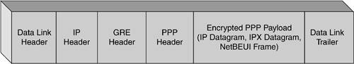
After the initial negotiation, two parties exchange a series of messages that include 12 standard call and connection management messages. For more information about the structure of PPTP control connection messages, see RFC 2637. PPTP Data TunnelingPPTP data tunneling is performed through multiple levels of encapsulation. The structure is shown in Figure 19-5. The initial PPP payload is encrypted and encapsulated with a PPP header to create a PPP frame. The PPP frame is then encapsulated with a modified GRE header. GRE uses client protocol ID number 47. Figure 19-5. PPTP Data Tunneling
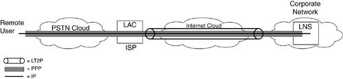
NOTE For troubleshooting purposes, it is important to remember that PPTP uses the reserved TCP port 1723. The PPTP control connection carries PPTP call control and management messages that maintain the PPTP tunnel. The GRE protocol ID is 47. L2TPL2TP is addressed in IETF's RFC 2661 standard. It combines the best features of two existing tunneling protocols: Cisco's Layer 2 Forwarding (L2F) and Microsoft's PPTP.[5] L2TP is an extension of PPP and is an important component for VPNs. L2TP is considered more scalable than PPTP and it also operates in client-server mode. Similar to PPTP, the L2TP tunnel can be started from the remote PC back to the L2TP network server (LNS), or from the L2TP-enabled access concentrator (LAC) to the LNS (see Figure 19-6). Although L2TP still uses PPP, it defines its own tunneling protocol, depending upon the transport media rather than using GRE. Figure 19-6. L2TP Architecture Model
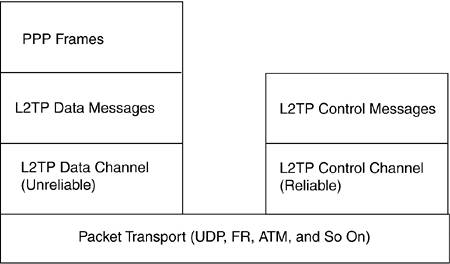
L2TP can also transport various Layer 3 protocols other than IP, although not all implementations support this feature. L2TP can use PAP, CHAP, and EAP for authentication; however, a major difference is support for the use of IPSec, which can secure traffic all the way from the end user's PC to the corporate network. L2TP uses two types of messages: control and data (see Figure 19-7). Control messages are used in the establishment, maintenance, and clearing of tunnels and calls. Data messages encapsulate PPP frames that are carried over the tunnel. Control messages use a reliable control channel within L2TP to guarantee delivery, while data messages are not retransmitted when packet loss occurs. Figure 19-7. L2TP Protocol Structure
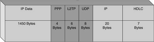
PPP frames are passed over an unreliable data channel and are first encapsulated by an L2TP header, and then by a packet transport such as User Datagram Protocol (UDP), Frame Relay, or Asynchronous Transfer Mode (ATM). Control messages are sent over a reliable L2TP control channel that transmits packets in-band over the same packet transport. Sequence numbers are required in all control messages. The numbers provide reliable delivery on the control channel because the packets can be reordered to detect lost packets. An example for L2TP encapsulation over high-level data link control (HDLC) and IP is shown in Figure 19-8, and a general tunnel structure is shown in Figure 19-9. Figure 19-8. L2TP Encapsulation over HDLC and IP, Where the Maximum Size Is 1500 Bytes (L2TP Encapsulation Is in Dark Gray)
Figure 19-9. The General Tunnel Structure of L2TP
The L2TP protocol is defined in RFC 2661 and is referred to as L2TPv2. The IETF Extension Group recently released version 3. The new standard includes PPP-related changes and the transition from both a 16-bit session ID and control connection ID, to 32-bit IDs. The new RFC 3193 covers "Securing L2TP using IPSec," to build private and authenticated PPP connections over the Internet. This feature is already implemented in IOS 12.2(4).T and results in the interoperability between Windows 2000 and XP, and Cisco routers. (The Microsoft version is called L2TP+IPSec.) The recent developments in the VPN industry are closely related to Layer 3 and especially IPSec tunneling. The following section focuses on this topic. |

EAN: 2147483647
Pages: 235