Section 8.1. IP Storage
8.1 IP Storage
IP storage refers to a group of technologies that provide block-level access between storage devices or servers using the IP family of protocols as a transport mechanism. The astute reader would argue, and rightly so, that data access over IP networks has been in use for quite some time ”for example, in applications accessing data from a server using the CIFS or NFS protocol. The difference is that the applications are file oriented and the translation from file-level I/O to block-level I/O happens at the NAS device or server, after the request has made its way across a network. With IP SANs, the requests and responses traveling across a network consist of block-level I/O and not file-level I/O.
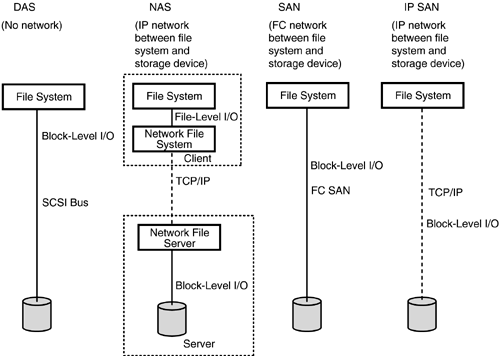
Figure 8.1 shows the basic outlines of direct-attached storage (DAS), network-attached storage (NAS), storage area networks (SANs), and IP SANs. Observe the following:
-
With DAS, no network is involved.
-
With NAS, the IP network is between the file system and the storage device. Of course, one can have a non-IP network for NAS as well, but IP is the most prevalent . The I/O flowing across the network is file-level I/O. There are always exceptions to the rule, and an example here is a NAS device such as EMC's Celerra HighRoad that is connected to both a LAN and a SAN. This scenario is described in more detail in Chapter 6 (Section 6.6).
-
With storage area networks, the network is between the file system and the storage device; however, the I/O is block-level I/O and not file-level I/O. Classic SANs almost always use Fibre Channel for the network.
-
With IP storage, the network is again between the file system and the storage device, except in this case the network is a classic IP network.
Figure 8.1. DAS, NAS, SAN, and IP SAN
8.1.1 Why IP Storage?
IP storage grew out of the realization that it is probably not necessary to have two kinds of networks. These two networks are the IP and Ethernet networks connecting clients and servers (the so-called front-end network ), and storage networks are termed the back-end networks between servers and storage.
IP storage is likely to make rapid progress for several reasons:
-
IP is an established, well- understood technology that has solved many of the problems involved in running IP-over-Ethernet, ATM, and so on.
-
IP routing is an established technology that provides multiple paths between servers and storage devices in the face of a dynamically changing network.
-
In some sense, the problem of storage management is the equivalent of the well-known problem of managing IP-based networks.
-
IP provides for geographical separation between servers and storage units.
-
IP networks are used to build the largest-scale networks in the world, including the Internet, and have addressed many of the scalability and congestion issues.
Proponents of IP storage argue that IP has won and it is time to move on from "IP-over-everything" (Ethernet, Token Ring, ATM, Gigabit Ethernet, and so on) to "Everything-over-IP" (including SCSI command data blocks, or CDBs ”more simply, SCSI-commands/results-over-IP, and so on).
Chapter 4 explained that there are two worlds: the worlds of I/O channels and networks. Channels such as SCSI typically operate over smaller distances, are dedicated to a limited set of purposes, and typically are implemented with a lot of the functionality built into hardware. Networks, on the other hand, can operate over larger distances, are more general-purpose in nature, and comparatively get more of their functionality from software. Whereas Fibre Channel represents an effort to combine the best of both worlds from a channel-centric view, IP storage represents an attempt to combine the best of both worlds from a network-centric point of view.
The new term storage wide area network ( SWAN ) refers to the deployment and use of IP storage technologies over IP-based wide area networks.
The following sections describe the various IP storage technologies and, where relevant, provide details of Microsoft implementation of those technologies.
8.1.2 iSCSI
iSCSI (short for "Internet SCSI") is a protocol that specifies a means of establishing one or more TCP/IP connections between two devices to be used for exchanging SCSI commands, responses, and status information over those established TCP connections. To put it differently, iSCSI is an end-to-end encapsulation protocol that encapsulates SCSI command, response, and status information.
Figure 8.2 shows how IP, TCP, iSCSI, and SCSI are related in terms of encapsulation. The iSCSI packet is the data or payload for the TCP/IP stack, and it carries the SCSI command and data as its data and payload. The iSCSI header provides information about how to extract and interpret the SCSI commands within the payload. The TCP header is responsible for guaranteed , sequential delivery of packets, and the TCP packet itself is the data and payload of an IP packet. The IP header facilitates routing.
Figure 8.2. iSCSI Protocol Encapsulation

Of the three major IP storage protocols ”iSCSI, FCIP (Fibre Channel over IP), and iFCP (Internet Fibre Channel Protocol) ”iSCSI is the only one that has no relationship to Fibre Channel other than as a complete replacement for Fibre Channel. In lacking any mention of Fibre Channel, Figure 8.2 shows that iSCSI evolved with no Fibre Channel support in mind.
iSCSI is layered on top of the existing layers of TCP/IP, IP, and lower-level hardware protocols that support TCP/IP (such as Ethernet and Gigabit Ethernet).
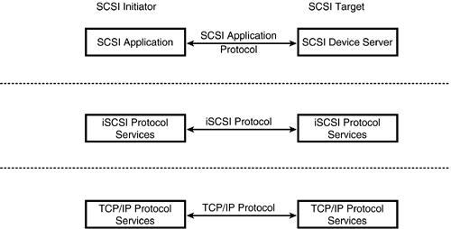
As Figure 8.3 shows, SCSI is an application protocol. iSCSI provides services to the SCSI application protocol and avails itself of the services of TCP/IP for reliable transmission, routing, and so on.
Figure 8.3. iSCSI Protocol Layers
All iSCSI devices (targets as well as initiators) have two different names :
-
An iSCSI address , which consists of an IP address, a TCP port, and an iSCSI name in the format "<domain name>:<port number>:<iSCSI name >".
-
An iSCSI name in a human-readable format ”for example, "FullyQualifiedName.DiskVendor.DiskModel.Number".
The naming authority iSNS (Internet Storage Name Service) is common to iSCSI, iFCP, and FCP (Fibre Channel Protocol). iFCP and FCP are described in Section 8.1.5. In addition to using iSNS as a naming service, iSCSI has an accompanying specification that deals with defining a MIB (Management Information Base) for SNMP-based management of iSCSI devices. iSCSI also defines a process to implement remote booting.
iSCSI establishes sessions between initiator and target. These are iSCSI sessions, and a single iSCSI session may use one or more TCP sessions. When the session is established, the two sides (initiator and target) negotiate options such as security, buffer size , and whether or not unsolicited data can be sent. An iSCSI session may end normally with a logout or terminate because of an error. Regardless of how many TCP sessions are used, the iSCSI protocol guarantees that the SCSI commands and responses are delivered in order. Note that TCP guarantees sequential delivery for a particular TCP session but does not provide any semantics to synchronize traffic over two different TCP sessions. Hence it is up to the iSCSI protocol to implement synchronization among the multiple different TCP sessions when needed. Some iSCSI requirements here include the following:
-
Different SCSI commands may flow over different TCP sessions.
-
All data and parameters corresponding to a particular SCSI command must flow over the same TCP session as the one on which the command originated.
-
iSCSI defines the concept of an initiator tag. All responses will have the corresponding initiator tag sent in the original command. An initiator must ensure that initiator tags are unique and not reused, until all outstanding responses to that tag are received back at the initiator. The tags must be unique per initiator (Windows NT is a multitasking system, and the initiator may be acting on behalf of multiple processes and applications).
-
iSCSI defines the concept of command numbering to ensure sequential delivery of commands across multiple TCP sessions.
-
iSCSI also defines an end-to-end CRC (cyclic redundancy check) mechanism because layer 2 CRC checking (e.g., Gigabit Ethernet) or layer 3 (TCP/IP checksums) may be unreliable, especially when one considers that there may be interposing IP devices (e.g., network address translators, routers) ”hence the need for a guaranteed end-to-end error detection mechanism. This is consistent with the fact that storage providers are historically more sensitive to data integrity checking.
iSCSI also has its disadvantages. It introduces issues such as security, congestion control, and quality of service. However, these issues are mostly related to issues with operating a TCP/IP network, which are well-understood issues.
8.1.3 Windows NT iSCSI Implementation
Microsoft has indicated that it is actively implementing iSCSI support in Windows NT. There is no exact release period, especially since the iSCSI specification itself is not yet finalized. The fact that the initial iSCSI draft specification was finalized in the summer of 2002 should help firm up iSCSI support from Microsoft. Current indications are that Microsoft will have native iSCSI support in the post-Windows Server 2003 time frame, but this is something only time will tell, and the reader is cautioned not to make any plans on the basis of this estimate. iSCSI support certainly is not natively part of Windows Server 2003.
Figure 8.4 shows the architecture for the Windows NT iSCSI implementation.
Figure 8.4. iSCSI Architecture
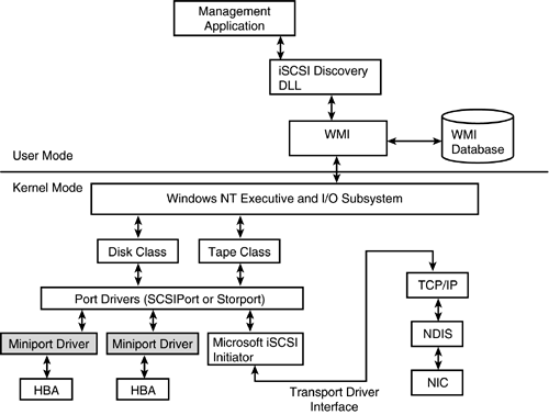
The iSCSI initiator is implemented as a miniport driver for either a SCSIPort miniport or a Storport miniport.
The iSCSI discovery dynamic link library (DLL) tracks all changes dynamically and acts as a single repository for all LUNs discovered through any mechanism, including iSNS client or port notification. The discovery DLL provides an API for management applications to discover new LUNs and, if appropriate, a means for the management application to direct the discovery DLL to log in to the new LUN.
Highlights of Microsoft iSCSI plans include the following:
-
The focus is on implementing iSCSI on the Windows Server 2003 platform, but supporting it on the Windows 2000 platform is also being considered . Only a final announcement at the time when the software is actually made available will provide any certainty .
-
The focus is on implementing iSCSI on the Windows Server 2003 platform. However, Microsoft will also provide iSCSI code for the Windows 2000 and Windows XP platforms. This code is expected to be available within months of the Windows Server 2003 release.
-
Microsoft will provide code for an iSNS server and client.
-
Microsoft emphasizes the use of IPsec as a data protection and security mechanism.
-
The idea is to focus on iSCSI initiator implementation, and there are no current plans to implement iSCSI target on the Windows NT platform.
-
All communication between discovery DLL and iSCSI initiator is through Windows Management Instrumentation (WMI). The discovery DLL might turn into a service, or it might not.
-
A core feature is the separation of target discovery from target access. A management application initiates access via the discovery DLL, which in turn contacts the miniport driver (via WMI). The miniport driver reports a BusChangeDetected event (described in the Windows NT DDK), causing a device enumeration. From this point on, device enumeration is no different; for example, a Report LUNs command will be sent to the newly discovered device.
-
The use of IPsec (IP security) for security considerations is strongly advised.
-
The use of WMI for management and reporting purposes is encouraged. It is expected that some WMI classes will be required to be implemented and others may be recommended. Exact details are available only privately through an agreement with Microsoft. [1]
[1] To correspond with the relevant folks at Microsoft, send e-mail to iscsi@microsoft.com.
Even though a lot of the information provided in this chapter is speculative, it is provided because the widespread adoption of iSCSI can be accomplished only with native operating system support. This means that the reader needs to be aware of OS vendor plans in this area. However, the reader is also cautioned about the speculative nature of the information.
8.1.4 FCIP
Fiber Channel over IP provides a means of preserving existing investment in equipment and of connecting geographically distributed SANs using a TCP/IP-based tunneling protocol. The IETF FCIP specification covers the following areas:
-
Encapsulation of Fibre Channel frames being transported via TCP/IP, including the encapsulation required to create a virtual Fibre Channel link connecting Fibre Channel devices and fabric.
-
Specification of the TCP/IP environment, including security, congestion control, and error recovery. FCIP requires both Fibre Channel and TCP to play a role in error handling and recovery.
Figure 8.5 shows the details of FCIP encapsulation.
Figure 8.5. FCIP Encapsulation
![]()
The SCSI data forms the payload. The SCSI data is encapsulated within Fibre Channel Protocol (FCP), which itself is encapsulated within FCIP. TCP thinks of FCIP as its own payload. In the encapsulation, IP is unaware of the Fibre Channel nature of the data, and the Fibre Channel part, in turn, is completely unaware of the presence of IP.
Encapsulation protocols typically have implementation overheads as the data goes through a series of layers, with some protocol processing being executed at each layer. FCIP is no exception to the rule of having some implementation overheads. To the IP network in Figure 8.6, the FCIP gateways appear to be IP devices; to the Fibre Channel networks, however, the FCIP gateways appear to be Fibre Channel devices. Only the two FCIP gateways communicating with each other are aware of the Fibre Channel encapsulation.
Figure 8.6. FCIP Connecting Two SANs

Figure 8.6 shows how FCIP is typically used to connect two distinct and separate SAN islands. With FCIP, the storage network remains Fibre Channel “centric, and all addressing, routing, and other operational aspects of the storage network remain unaltered ”that is, just as in a Fibre Channel network. FCIP depends on TCP/IP for routing and management, including congestion control. FCIP depends on both TCP/IP and FCP to detect and correct data corruption. FCIP also relies on both TCP/IP and Fibre Channel to ensure data loss recovery. FCIP maps Fibre Channel addresses to IP addresses. FCIP provides connectivity between E ports. (Chapter 4 describes different types of Fibre Channel ports.)
Typical FCIP applications could include the following:
-
Remote backup and restore
-
Remote backup to ensure a geographical disaster recovery solution
-
At sufficiently high bandwidth between the two FCIP gateways (a distinct possibility with the overaccumulation of geographical cable), synchronous mirroring and geographical data sharing, as well as shared or pooled storage
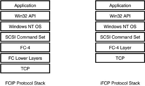
FCIP requires no changes to the Fibre Channel Network. Figure 8.7 shows the FCIP and iFCP protocol stacks. (iFCP is described in Section 8.1.5.) Note that the Fibre Channel functional layers, including FC-4 and the lower Fibre Channel layers, remain unaltered in a FCIP environment. Compared to the typical hierarchy of file system, volume management, class, and port layers in Chapter 1, the SCSI command layer exists in this model up to the port layer. Thus the FC-4 and lower layers in Figure 8.7 would be implemented in hardware below the Windows NT port driver layer. The one caveat is that normally one would expect hardware to simply provide much of the functionality beneath the port driver. In this case there is also a TCP/IP stack that is very often implemented in software.
Figure 8.7. Comparison of FCIP and iFCP Protocol Stacks
FCIP has some advantages compared to IP-over-Ethernet. Whereas Ethernet packets typically carry approximately 1,500 bytes of data, FCIP frames carry approximately 2,000 bytes. When one considers that Ethernet frames, with Gigabit Ethernet, support jumbo frames that hold typically 8K or more, this advantage is mitigated.
The problem with FCIP is still that customers have two networks to maintain. FCIP is expected to be used more as a way to do channel extension or remote mirroring to an existing device, than as a "new" storage protocol being deployed natively at the host level.
8.1.5 iFCP
Internet Fibre Channel Protocol is a gateway-to-gateway protocol that allows two Fibre Channel networks to connect to each other via a TCP/IP transmission network. Essentially, the Fibre Channel fabric components are replaced by the TCP/IP switching and routing elements. Whereas FCIP aims at providing SAN-to-SAN connectivity, iFCP targets more at providing connectivity for individual Fibre Channel devices into an IP network.
iFCP is a gateway-to-gateway protocol that uses two gateway devices to enable the rest of the devices in the Fibre Channel SAN to remain unmodified while allowing connectivity. Figure 8.8 shows a typical iFCP deployment.
Figure 8.8. iFCP Deployment
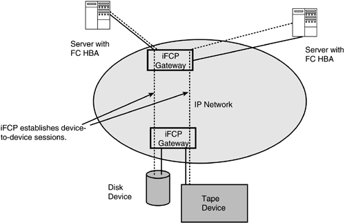
Two iFCP gateways are deployed as edge devices in an IP network. Fibre Channel “enabled nodes such as disks, tapes, and servers may be connected to the gateways. As Figure 8.8 shows, the two gateways establish an IP tunnel that carries device-to-device session traffic. Thus, iFCP works on a device-to-device basis, whereas FCIP works more like an Ethernet bridge that forwards everything from one island to another.
iFCP supports Fibre Channel Protocol (FCP), which is the standard for transporting SCSI commands and responses on a serial link. As shown in Figure 8.7, the iFCP protocol stack replaces the FC-2 layer (the transport layer of Fibre Channel described in Chapter 4) with a TCP transport layer, but leaves the FC-4 layer untouched. iFCP messaging and routing services terminate at the gateway. Thus, even though device-to-device connectivity exists, the two Fibre Channel SANs remain physically apart. Think of this scenario as somewhat equivalent to broadcast frames that do not propagate through a router. iFCP provides connectivity only between Fibre Channel F ports. (See Chapter 4 for a description of the various Fibre Channel port types and their functionality.) iFCP creates multiple TCP/IP sessions, and these sessions are from one Fibre Channel device to another.
Comparing the FCIP and iFCP protocol stacks in Figure 8.7, one notices that FCIP implements all layers of the Fibre Channel protocol, whereas iFCP implements only layer 4. One can thus conclude that FCIP is more Fibre Channel “centric.
iFCP uses TCP/IP to ensure reliable data transmission. This means that the underlying IP network itself need not be reliable. The iFCP specification allows for high latencies in networks, and this helps it operate in low-latency unreliable networks where the network appears to be a high-latency reliable network, thanks to the efforts of TCP in providing a reliable sequential transport mechanism. Because iFCP uses multiple TCP/IP connections, it is more robust and less prone to congestion than when a single TCP/IP connection is used for all storage device connectivity.
iFCP gateway devices provide a means for storage devices to register with an iSNS name server (see the next section).
8.1.6 Internet Storage Name Service
The Internet Storage Name Service ( iSNS ) provides registration and discovery services for storage devices. Because iSNS is a lightweight protocol, it can easily be implemented in servers as well as storage devices. iSNS provides a single model that can apply to both SCSI and Fibre Channel devices, thus facilitating the mapping between IP storage and Fibre Channel devices. Fibre Channel “based devices register with iSNS through means provided by an iFCP gateway. iSCSI devices register directly with the iSNS service. Initiators locate the iSNS server in one of two ways:
-
Through statically configured information
-
Through the Service Location Protocol (SLP)
iSNS also provides zoning functionality through the concept of discovery domains, which allow an administrator to specify groups of devices. When a member of the group queries the iSNS server, the returned results are limited to members of the same group. In addition, iSNS provides notification services ”for example, when a new target device comes online.
iSNS servers play an important role in storage security. One way of enforcing security is through discovery domains. In other words, iSNS servers can store and enforce access control policy (that is, which initiators are allowed to access which devices). In addition, iSNS servers play a role in providing a mechanism for a device to register its public key certificate with the iSNS server, and the server can then provide this information to other devices that query it.
Microsoft appears to be a proponent of the iSNS protocol. It has not yet publicly indicated whether it will ship an iSNS server, an iSNS client, or both.
8.1.7 TCP Offload Solutions
With the advent of IP storage, it has become even more imperative to have an efficient TCP/IP implementation. Testing shows that significant CPU resources can be consumed by TCP/IP processing overheads. Even the TCP/IP checksum calculations by themselves can be a significant drain on CPU resources. In addition, the data is copied multiple times, and this overhead can add up when one considers the vast number of data copies that are made.
For example, TCP must provide sequential delivery (not provided by IP), so it must temporarily store packets that arrive out of sequence. This means that data is copied into a temporary buffer and then later copied into the user buffer. The hardware requirements for supporting even something as simple as receiving packets out of order can be onerous. A 1-Gbps (gigabits per second) WAN link can require 16MB of memory to store and reassemble nonsequential packets. A 10-Gbps WAN link can require as much as 125MB of memory. The point is that the number of situations in which buffer copies are needed must be reduced, either through more efficient software or through enhanced hardware, or a combination of the two.
TCP offload solutions developed recently make an effort to move some of the overhead to a hardware network interface adapter. With the increasing importance of TCP/IP performance, given the advent of IP storage, these efforts have only accelerated. The proposed solutions include the following:
-
Offload the entire TCP/IP stack to hardware. Although this is the best approach in terms of performance, it is also the most ambitious and has some tough issues to solve ”for example, coordination between different TCP stacks running on different NICs (network interface cards) on the same Windows NT server.
-
Offload the TCP data movement and checksum generation, but not the connection control.
-
Offload "normal" processing, but handle the exceptions in software.
-
Offload some IPsec and even some iSCSI processing into the hardware.
Windows 2000 introduced NDIS (Network Driver Interface Specification) version 5.0, which includes support for TCP/IP offload. Specifically, Windows 2000 introduced support for the following functions:
-
Offloading the TCP/IP checksum calculation to hardware for both sending (generating checksum) and receiving (verifying checksum).
-
Offloading TCP segmentation wherein data that is larger than the maximum transmission unit can be passed in and the hardware will accomplish the required segmentation into multiple packets.
-
Offloading IPsec implementation. IPsec is a standard ( applicable to both IPv4 and IPv6) that ensures data integrity and authentication on a per-packet basis. IPsec can be operated in two modes: a transport mode that ensures data integrity and authentication between two end user applications, or a tunnel mode that ensures security in data exchange between two routers. Both can be offloaded.
-
Fast packet forwarding, wherein Windows 2000 routing code can directly forward a packet from one network port to another without having the packet ever enter host memory.
| |
| Top |
EAN: 2147483647
Pages: 111