Section 4.7. Clusters
4.7. ClustersIt's possible to cluster your virtual servers, which run applications that are cluster-aware such as Exchange or MSSQL. This functionality has been enhanced with the use of raw device mapping (see the previous section for details). Clusters provide a high-availability configuration between two or more servers working together as one. Redundancy on the software and/or hardware level allows for the high availability. 4.7.1. Cluster TypesThere are a number of clustering solutions you can consider, such as the following:
4.7.1.1. Cluster in a BoxCluster in a box allows for two or more virtual machines running on the same ESX Server to run a cluster-aware application. This type of cluster provides redundancy for software failures and administrative errors. 4.7.1.2. Cluster across BoxesA cluster across boxes allows for two or more virtual machines running on separate ESX Servers and provides both software and hardware redundancy. 4.7.1.3. Consolidated ClusterA consolidated cluster configuration basically allows you to consolidate a number of hardware clusters onto two physical ESX Servers. Let's say you have three clusters with two nodes each. By consolidating your cluster onto ESX Server, you reduce the number of physical servers you need by two-thirds, going from six to two. 4.7.1.4. Cost-Effective Standby HostA cost-effective standby cluster configuration lets you place all of your failover nodes on a single ESX Server while maintaining your primary nodes on physical servers. This allows for a physical server consolidation ratio of nearly 50 percent. 4.7.1.5. Network Load BalancingVMware permits the deployment of parallelization clustering utilizing Microsoft's Network Load Balancing. This type of clustering helps you scale a service, such as VPN or Web, by balancing and distributing the traffic amongst the virtual servers that are a part of the cluster so that the load is shared equally. 4.7.1.6. Geo-ClusteringGeo-clustering, or geographically distributed clustering, allows for cluster nodes to exist in remote sites. VMware has published a whitepaper discussing how this is implemented with the EMC Symmetrix Remote Data Facility (SRDF). Neither writer of this book has implemented this solution yet, but we strongly suggest reading the whitepaper to see what is available now and to imagine what the future holds. You can find the white paper at www.vmware.com/pdf/SRDF_wp_eng.pdf. 4.7.2. Building a Two-Node Cluster in a Box with Windows 2003 Server, Enterprise EditionWe will build the most basic of clusters: a cluster in a box. This is the cluster type you build when you go to virtual infrastructure with ESX Server and VirtualCenter class. All clusters, regardless of the type, need very similar hardware. Each node must be configured with the following:
We will call our cluster nodes node1 and node2. The cluster itself will be called vcluster. Figure 4.7 shows the basic configuration of node1 before adding the additional hardware it needs for a cluster in a box. Figure 4-7. Node1, Basic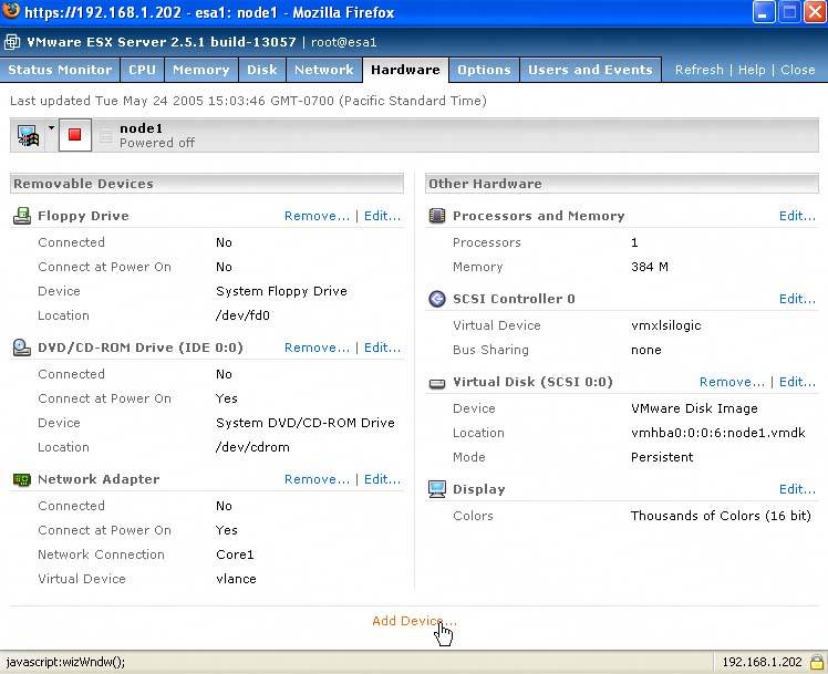 Notice it has only one NIC, no quorum or data drives, and only one SCSI controller. First, we'll add the drives and the controller. Click Add Device. Select Hard Disk (see Figure 4.8). Figure 4-8. Selecting Hard Disk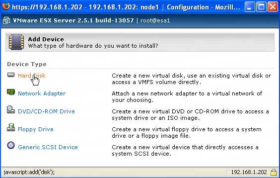 Click Blank (see Figure 4.9). Figure 4-9. Clicking Blank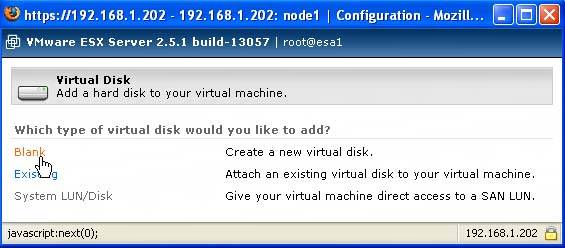 Name the .vmdk file something like v clusterquorum.vmdk (see Figure 4.10). Change the default size of the drive and then change the SCSI Node on which it will run (this last step creates the second SSI adapter). Figure 4-10. Naming the vmdk File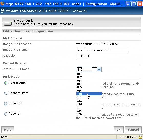 Click OK twice and you've just created your quorum disk and a new SCSI adapter. Look back on the Hardware tab of node1 to see the change (see Figure 4.11). Figure 4-11. Node1 with a Second SCSI Controller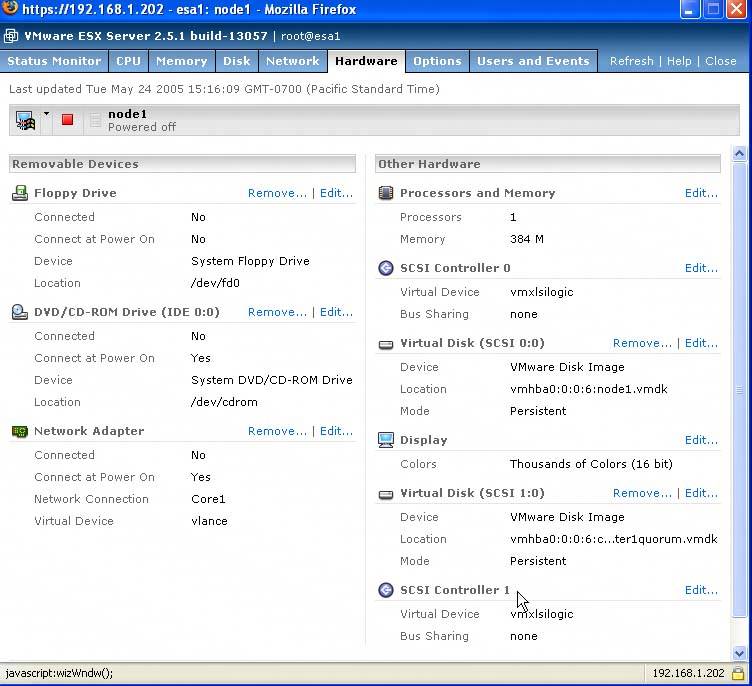 Change the bus sharing on the new SCSI Controller 1 to virtual on the Hardware tab of node1 by clicking Edit next to the new SCSI Controller 1. This brings up the SCSI Controller 1 Configuration page. Use the Bus Sharing dropdown menu and select virtual (see Figure 4.12). Figure 4-12. Changing Bus Sharing to Virtual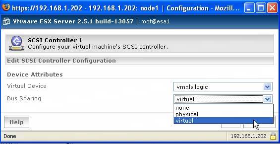 Click OK. Next, add the data drive(s) using the same process we did for the quorum, except place the data drives on SCSI node 1:1, 1:2, and so on depending on the number of data drives. For this example, we're only adding one additional drive, which we'll place on SCSI node 1:1. Next, add the additional NIC you'll need for the cluster heartbeat. Back on the Hardware tab for node1, click Add Device the same way you did to add the additional hard disk. Choose Network Adapter (see Figure 4.13). Figure 4-13. Adding the Heartbeat NIC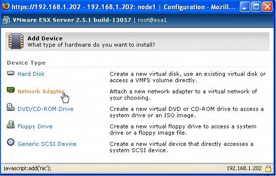 The Network Adapter configuration window appears. For this cluster, we already created a vmxnet (see Chapter 5) called Heartbeat, which is where this second NIC will route traffic (see Figure 4.14). The driver was changed from the vlance default vmxnet. Click OK. Figure 4-14. Heartbeat vmxnet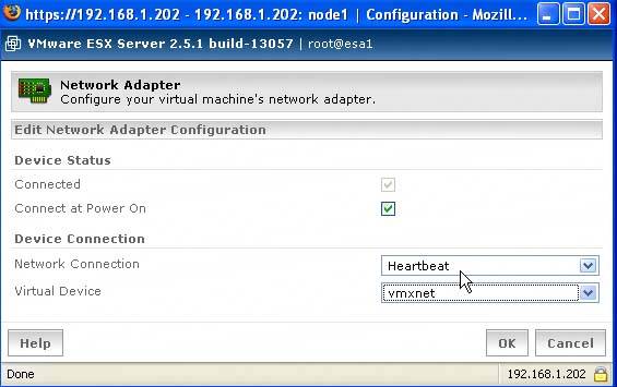 So, the final configuration of node1 is complete. Load the operating system on the disk on SCSI0. As soon as the operating system is loaded, install the VMware Tools. After VMware Tools are installed and you have rebooted your virtual machine, set the IP information for both your public and heartbeat network adapters. For your heartbeat adapter, you'll only need the IP address, which we set on a different subnet than our public, and then the subnet mask. If your public IP for node1 is 192.168.1.1/24, then you can set your heartbeat to 10.0.0.1/8. Once this has been completed, you will need to clone node1. Cloning node1 saves you time. To do this, shut down node1. Open the MUI and click Manage Files (see Figure 4.15). Figure 4-15. Cloning Node1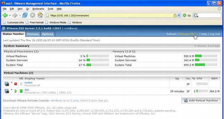 Drill down into the vmfs partition where your node1.vmdk is. Once there, check the node1.vmdk check box, and click Copy (see Figure 4.16). Figure 4-16. Copying Node1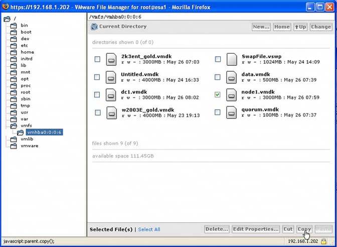 Once you've clicked Copy, then click Paste. A status bar appears and shows the progress of the copy. Once it's complete, a new virtual disk called copy_of_node1.vmdk appears. Mark the check box next to it and click Edit Properties (see Figure 4.17). Figure 4-17. Selecting Edit Properties of the .vmdk File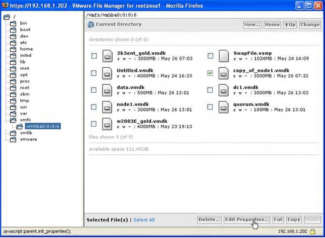 In the Properties window of your .vmdk file, you can rename the virtual disk to node2. You can also set permissions here as well (see Figure 4.18). Figure 4-18. Changing the Name of the .vmdk File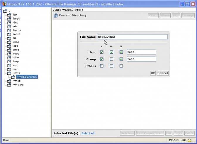 Click OK. You have now nearly completed cloning the virtual disk of node1, which you'll use for node2. Power down node1 and create the same configuration for node2 as you did for node1, ensuring you give it a second network card for the heartbeat. Also, make sure that the quorum and data drives point to the existing drives you set up on node1. Don't forget to change the SCSI controller Bus Sharing to virtual. When you've completed the setup for node2 in order for it to run without a name conflict, you'll need to run either Sysprep or a tool we prefer from Sysinternals.com called NewSID. Sysprep requires you to input the license key, while NewSID does not. Running NewSID allows you to reSID your cloned disk, as well as rename the virtual machineit still thinks it's node1 because it's a clone. Rename it to node2 and you can change the IP information prior to rebooting for both the public and heartbeat network adapters. After you've run NewSID and changed the virtual machine's name and IP information for both NICs, power down node2. Power up node1. When you're logged into it, you'll need to set the IP information for your heartbeat. As I mentioned already in this chapter, I created a vmnet for the heartbeat. Since this cluster is being built with Windows 2003 Server, Enterprise Edition, the cluster service is installed. Prior versions of the OS, you had to install the cluster service separately. Log into node1 and start Cluster Administrator (see Figure 4.19). Figure 4-19. Starting Cluster Administrator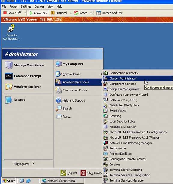 Select Create New Cluster from the dropdown menu (see Figure 4.20). Figure 4-20. Selecting Create New Cluster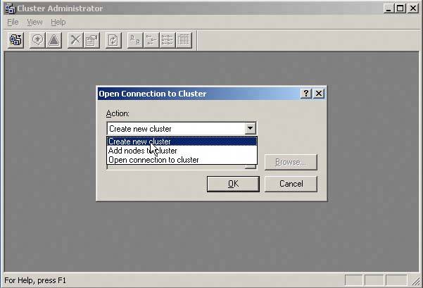 Give your cluster a name (see Figure 4.21). (Note that this will be the NetBIOS name of the cluster.) Figure 4-21. Naming Your Cluster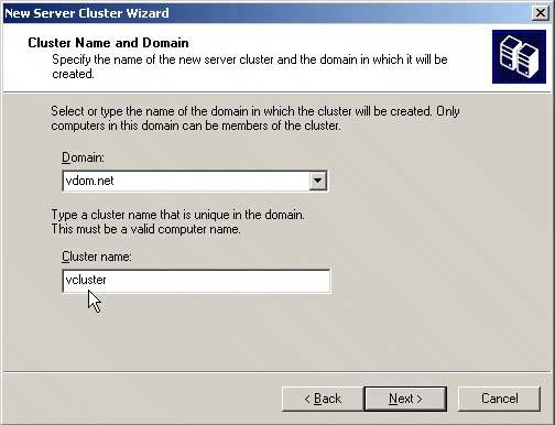 Select the cluster node you're adding to the cluster. By default, it should be pre-populated with node1 (see Figure 4.22). Figure 4-22. Adding Cluster Node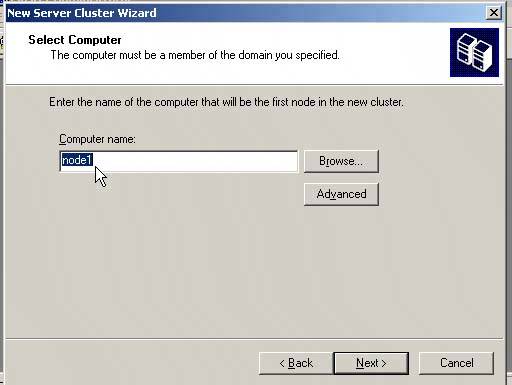 The Cluster Administrator then conducts an analysis of the virtual machine configuration (see Figure 4.23). Figure 4-23. Analyzing the Cluster Configuration Once the analysis is complete, click Next. You'll then need to input the cluster's IP address, which is different from the public or heartbeat IP address (see Figure 4.24). Figure 4-24. Inputting the Cluster's IP Address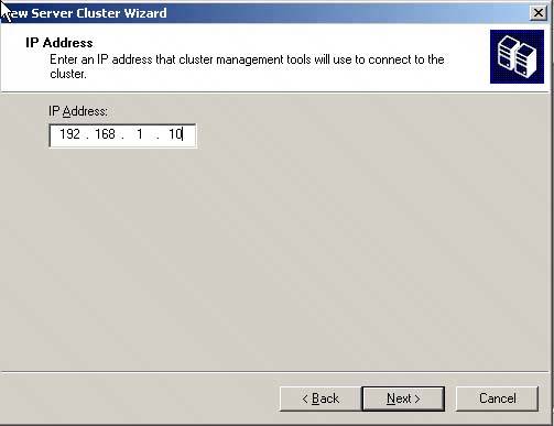 Next, you'll need to input the Cluster Service account name and password. In this example, the administrator account is used, but this is strictly for demonstrative purposes and is not recommended (see Figure 4.25). Figure 4-25. Inputting the Cluster Service Account Name and Password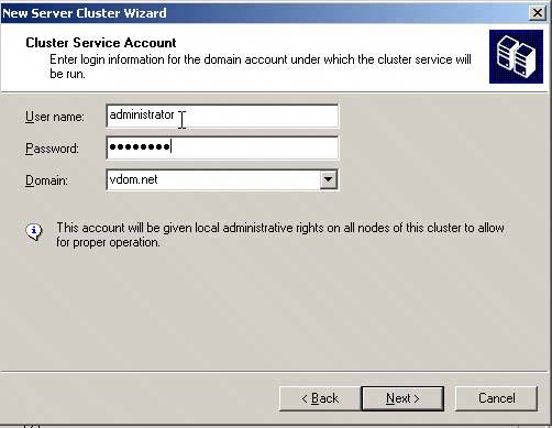 Review the Proposed Cluster Configuration window. You may need to click the Quorum button and ensure that the quorum drive is selected correctly (see Figure 4.26). Figure 4-26. Reviewing the Proposed Cluster Configuration Window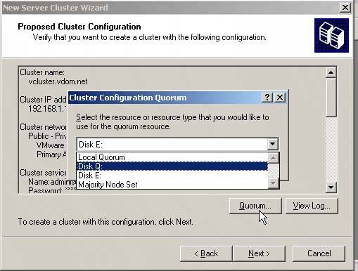 Finally, the first node of the cluster is created (see Figure 4.27). Figure 4-27. Creating the First Node of the Cluster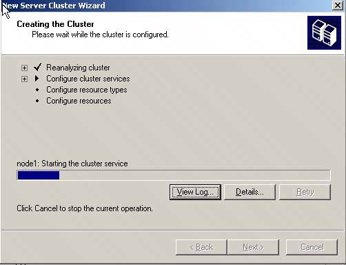 Click Finish when it's done. Adding node2 to the cluster is simple. Power on node2. Back on node1, open Cluster Administrator. Right-click your cluster and select New | Node and then click Next (see Figure 4.28). Figure 4-28. Adding Node2 to the Cluster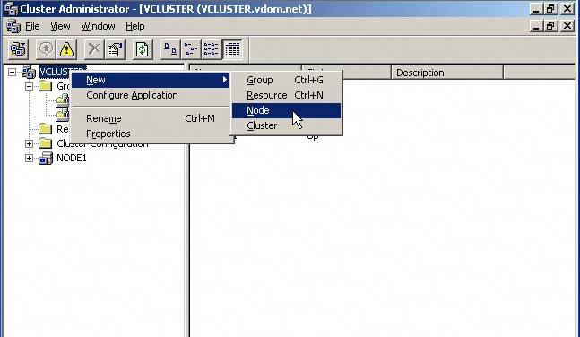 You can either type or browse for node2 and then click Add. Click Next (see Figure 4.29). Figure 4-29. Selecting the Additional Node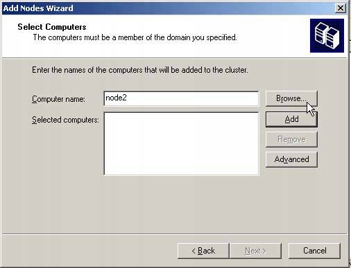 Analysis of node2 begins. When it's complete and there are no errors, click Next (see Figure 4.30). Figure 4-30. Analyzing the Configuration of Node2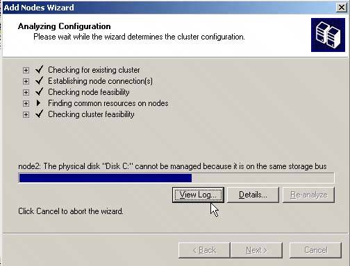 You'll then be prompted for the Cluster Service Password. Enter it and click Next. The Proposed Cluster Configuration window appears. Review your cluster and once you're satisfied, click Next. This completes the process of adding node2 to the cluster. Once finished, click Next and then click Finish. To test your cluster, try failing over a cluster resource. You have now completed building a cluster in a box, albeit a simple cluster. VMware ESX Server allows for the easy creation of highly redundant systems that improve availability. For more information on all types of clustering, read the chapter on clustering in the VMware ESX Server Administrator's Guide at www.vmware.com/pdf/esx25_admin.pdf as well as the white paper on Geo-clustering provided earlier. |
EAN: 2147483647
Pages: 173