Parallel ATA
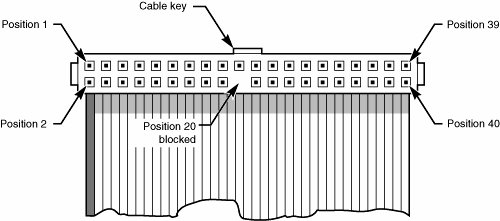
| Parallel ATA has unique specifications and requirements regarding the physical interface, cabling, and connectors as compared to Serial ATA. The following sections detail the unique features of parallel ATA. Parallel ATA I/O ConnectorThe parallel ATA interface connector is normally a 40-pin header-type connector with pins spaced 0.1" (2.54mm) apart, and generally it is keyed to prevent the possibility of installing it upside down (see Figures 7.2 and 7.3). To create a keyed connector, the manufacturer usually removes pin 20 from the male connector and blocks pin 20 on the female cable connector, which prevents the user from installing the cable backward. Some cables also incorporate a protrusion on the top of the female cable connector that fits into a notch in the shroud surrounding the mating male connector on the device. The use of keyed connectors and cables is highly recommended. Plugging an ATA cable in backward normally doesn't cause any permanent damage; however, it can lock up the system and prevent it from running. Figure 7.2. Typical parallel ATA (IDE) hard drive connectors. Figure 7.3. Parallel ATA (IDE) 40-pin interface connector detail. Table 7.3 shows the standard 40-pin parallel ATA (IDE) interface connector pinout.
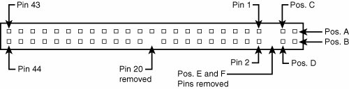
The 2 1/2" drives found in notebook/laptop-size computers typically use a smaller unitized 50-pin header connector with pins spaced only 2.0mm (0.079") apart. The main 40-pin part of the connector is the same as the standard parallel ATA connector (except for the physical pin spacing), but there are added pins for power and jumpering. The cable that plugs into this connector typically has 44 pins, carrying power as well as the standard ATA signals. The jumper pins usually have a jumper on them (the jumper position controls cable select, master, or slave settings). Figure 7.4 shows the unitized 50-pin connector used on the 2 1/2" parallel ATA drives in laptop or notebook computers. Figure 7.4. 50-pin unitized parallel ATA connector detail (used on 2 1/2" notebook/laptop parallel ATA drives with a 44-pin cable). Note the jumper pins at positions AD and that the pins at positions E and F are removed. A jumper usually is placed between positions B and D to set the drive for cable select operation. On this connector, pin 41 provides +5V power to the drive logic (circuit board), pin 42 provides +5V power to the motor (2 1/2" drives use 5V motors, unlike larger drives that typically use 12V motors), and pin 43 provides a power ground. The last pin (44) is reserved and not used. Table 7.4 shows the 50-pin unitized parallel ATA interface connector pinout as used on most 2 1/2" (laptop or notebook computer) drives.
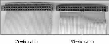
Parallel ATA I/O CableA 40-conductor ribbon cable is specified to carry signals between the bus adapter circuits and the drive (controller). To maximize signal integrity and eliminate potential timing and noise problems, the cable should not be longer than 18" (0.46 meters), although testing shows that 80-conductor cables can be used reliably up to 27" (0.69 meters) in length. Note that ATA drives supporting the higher-speed transfer modes, such as PIO Mode 4 or any of the Ultra-DMA (UDMA) modes, are especially susceptible to cable integrity problems and cables that are too long. If the cable is too long, you can experience data corruption and other errors that can be maddening. This is manifested in problems reading from or writing to the drive. In addition, any drive using UDMA Mode 5 (66MBps transfer rate), Mode 6 (100MBps transfer rate), or Mode 7 (133MBps transfer rate) must use a special, higher-quality 80-conductor cable (the extra conductors are grounds to reduce noise). I also recommend this type of cable if your drive is running at UDMA Mode 2 (33MBps) or slower because it can't hurt and can only help. I always keep a high-quality 80-conductor ATA cable in my toolbox for testing drives where I suspect cable integrity or cable length problems. Figure 7.5 shows the typical ATA cable layout and dimensions. Figure 7.5. Parallel ATA (IDE) cable, with 40-pin connectors and either 40- or 80-conductor cables (additional wires are grounded in 80-conductor versions).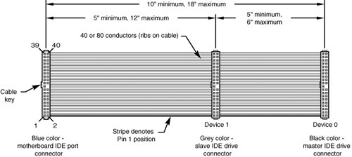 Note Most 40-conductor cables do not color-code the connectors, whereas all 80-conductor cables do color-code the connectors. Two primary variations of parallel ATA cables are used today: one with 40 conductors and the other with 80 conductors (see Figure 7.6). Both use 40-pin connectors, and the additional wires in the 80-conductor version are simply wired to ground. The additional conductors are designed to reduce noise and interference and are required when setting the interface to run at 66MBps (ATA/66) or faster. The drive and host adapter are designed to disable the higher-speed ATA/66, ATA/100, or ATA/133 modes if an 80-conductor cable is not detected. In such cases, you might see a warning message when you start your computer if an ATA/66 or faster drive is connected to a 40-conductor cable. The 80-conductor cable can also be used at lower speeds; although this is unnecessary, it improves the signal integrity. Therefore, it is the recommended version no matter which drive you use. Figure 7.6. 40-conductor (left) and 80-conductor (right) parallel ATA cables. I once had a student ask me how to tell an 80-conductor cable from a 40-conductor cable. I thought to myself, "Is this a trick question?" Perhaps they didn't know that each conductor in a ribbon cable can be seen as a rib or ridge in the cable. The simple answer is to count the ridges (conductors) in the cable. If you count only 40, it must be a 40-conductor cable, and if you count to 80, well...you get the idea! If you observe them side by side, the difference is clear: The 80-conductor cable has an obviously smoother, less ridged appearance than the 40-conductor cable. Note the keying on the 80-conductor cable that is designed to prevent backward installation, but note also that the poorly constructed 40-conductor cable shown in this example lacks keying. Most good 40-conductor cables include the keying; however, because it is optional, many cheaply constructed versions do not include it. Keying was made mandatory for all 80-conductor cables as part of the standard. Longer or Rounded CablesThe official parallel ATA standard limits cable length to 18" (0.46 meters); however, many of these cables that are sold are longer, up to even 36" (0.91 meters) or more in length. I've had many readers write me questioning the length, asking, "Why would people sell cables longer than 18" if the standard doesn't allow it?" Well, just because something is for sale doesn't mean it conforms to the standards and will work properly! I see improperly designed, poorly manufactured, and nonconforming items for sale all the time. Still, many people have used the longer cables and yet their systems seem to work fine, but I've also documented numerous cases where using longer cables has caused problems, so I decided to investigate this issue more thoroughly. What I've discovered is that you can use longer 80-conductor cables reliably up to 27" (0.69 meters) in length, but 40-conductor cables should remain limited to 18" just as the standard indicates. In fact, an attempt was made to change the parallel ATA standard to allow 27" cables. If you read www.t13.org/technical/e00151r0.pdf, you'll see data from a proposal that shows "negligible differences in Ultra DMA Mode 5 signal integrity between a 27", 80-conductor cable and an 18", 80-conductor cable." This extended cable design was actually proposed back in October 2000, but it was never incorporated into the standard. Even though it was never officially approved, I take the information presented in this proposal as empirical evidence for allowing the use of 80-conductor cables up to 27" in length without problems. To that, I would add another recommendation, which is that in general I do not recommend "rounded" ATA cables. A rounded design has not been approved in the ATA standard, and there is some evidence that they can cause problems with crosstalk and noise. The design of 80-conductor cables is such that a ground wire is interspersed between each data wire in the ribbon, and rounding the cable causes some of the data lines to run parallel or adjacent to each other at random, thereby causing crosstalk and noise and resulting in signal errors. In support of this, I read an interview with Rahul Sood in the March 2004 issue of CPU (www.computerpoweruser.com). Sood is the chief technology officer of a popular builder of high-end systems, called Voodoo PC (www.voodoopc.com). In the CPU interview, he said, "I don't agree with rounded cables, I never have. SATA cables are great, of course, but rounded [parallel ATA] cables are a different story because there is potential for noise. Any benchmarks that I've run on any of the rounded cables that we've tested show either errors generating over time or they're slower than good quality flat IDE cables." Of course, many people are using rounded cables with success, but my knowledge of electrical engineering as well as the ATA standard has always made me somewhat uncomfortable with their use. Although I cannot offer any specific test data to corroborate the findings of Sood, I do prefer to stick with 80-conductor ribbon cables of 27" or less in length in my own systems. Parallel ATA SignalsThis section describes some of the most important parallel ATA signals having to do with drive configuration and installation in more detail. This information can help you understand how the cable select feature works, for example. Pin 20 is used as a key pin for cable orientation and is not connected to the interface. This pin should be missing from any ATA connectors, and the cable should have the pin-20 hole in the connector plugged off to prevent the cable from being plugged in backward. Pin 39 carries the drive active/slave present (DASP) signal, which is a dual-purpose, time-multiplexed signal. During power-on initialization, this signal indicates whether a slave drive is present on the interface. After that, each drive asserts the signal to indicate that it is active. Early drives could not multiplex these functions and required special jumper settings to work with other drives. Standardizing this function to allow for compatible dual-drive installations is one of the features of the ATA standard. This is why some drives require a slave present (SP) jumper whereas others do not. Pin 28 carries the cable select signal (CSEL). In some older drives, it could also carry a spindle synchronization signal (SPSYNC), but that is not commonly found on newer drives. The CSEL function is the most widely used and is designed to control the designation of a drive as master (drive 0) or slave (drive 1) without requiring jumper settings on the drives. If a drive sees the CSEL as being grounded, the drive is a master; if CSEL is open, the drive is a slave. You can install special cabling to ground CSEL selectively. This installation usually is accomplished through a Y-cable arrangement, with the ATA bus connector in the middle and each drive at opposite ends of the cable. One leg of the Y has the CSEL line connected through, indicating a master drive; the other leg has the CSEL line open (conductor interrupted or removed), making the drive at that end the slave. Parallel ATA Dual-Drive ConfigurationsDual-drive parallel ATA installations can be problematic because each drive has its own controller and both controllers must function while being connected to the same bus. There has to be a way to ensure that only one of the two controllers will respond to a command at a time. The ATA standard provides the option of operating on the AT bus with two drives in a daisy-chained configuration. The primary drive (drive 0) is called the master, and the secondary drive (drive 1) is called the slave. You designate a drive as being master or slave by setting a jumper or switch on the drive or by using a special line in the interface called the cable select (CS) pin and setting the CS jumper on the drive. When only one drive is installed, the controller responds to all commands from the system. When two drives (and, therefore, two controllers) are installed, both controllers receive all commands from the system. Each controller then must be set up to respond only to commands for itself. In this situation, one controller must be designated as the master and the other as the slave. When the system sends a command for a specific drive, the controller on the other drive must remain silent while the selected controller and drive are functioning. Setting the jumper to master or slave enables discrimination between the two controllers by setting a special bit (the DRV bit) in the drive/head register of a command block. Configuring ATA drives can be simple, as is the case with most single-drive installations. Or it can be troublesome, especially when it comes to mixing two older drives from different manufacturers on a single cable. Most ATA drives can be configured with four possible settings:
Many drives simplify this to three settings: master, slave, and cable select. Because each ATA drive has its own controller, you must specifically tell one drive to be the master and the other to be the slave. No functional difference exists between the two, except that the drive that's specified as the slave will assert a signal called DASP after a system reset informs the master that a slave drive is present in the system. The master drive then pays attention to the drive select line, which it otherwise ignores. Telling a drive that it's the slave also usually causes it to delay its spinup for several seconds to allow the master to get going and thus to lessen the load on the system's power supply. Until the ATA specification, no common implementation for drive configuration was in use. Some drive companies even used different master/slave methods for different models of drives. Because of these incompatibilities, some drives work together only in a specific master/slave or slave/master order. This situation mostly affects older IDE drives introduced before the ATA specification. Most drives that fully follow the ATA specification now need only one jumper (master/slave) for configuration. A few also need a slave present jumper, as well. Table 7.5 shows the jumper settings required by most ATA drives.
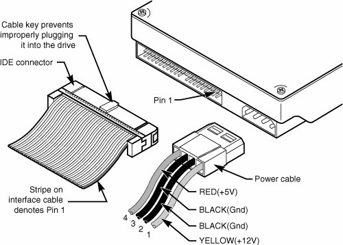
Note If a cable select cable is used, the CS jumper should be set On and all others should be Off. The cable connector then determines which drive will be master or slave. Figure 7.7 shows the jumpers on a typical ATA drive. Figure 7.7. Parallel ATA (IDE) drive jumpers for most drives.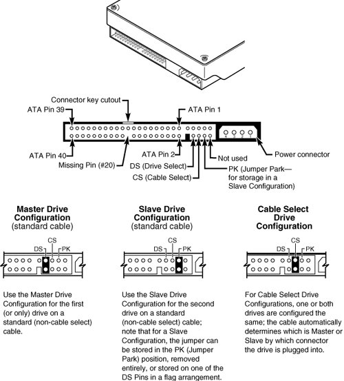 The master jumper indicates that the drive is a master or a slave. Some drives also require a slave present jumper, which is used only in a dual-drive setup and then installed only on the master drivewhich is somewhat confusing. This jumper tells the master that a slave drive is attached. With many parallel ATA drives, the master jumper is optional and can be left off. Installing this jumper doesn't hurt in these cases and can eliminate confusion; I recommend that you install the jumpers listed here. Note Note that some drives have these jumpers on the drive circuit board on the bottom of the drive, and as such they might not be visible on the rear. To eliminate confusion over master/slave settings, most newer systems now use the cable select option. This involves two things. The first is having a special parallel ATA cable that has all the wires except pin 28 running from the motherboard connector to both drive connectors. Pin 28 is used for cable select and is connected to one of the drive connectors (labeled master) and not to the other (labeled slave). Both drives are then configured in cable select mode via the CS jumper on each drive. With cable select, the drive that receives signals on pin 28 automatically becomes the master, and the other becomes the slave. Most cables implement this by removing the metal insulation displacement bit from the pin-28 hole, which can be difficult to see at a glance. Other cables have a section of pin 28 visibly cut from the cable somewhere along the ribbon. Because this is such a minor modification to the cable and can be difficult to see, cable select cables typically have the connectors labeled master, slave, and system, indicating that the cable controls these options rather than the drive. All 80-conductor UltraATA cables are designed to use cable select. With cable select, you simply set the CS jumper on all drives and then plug the drive you want to be the master into the connector labeled master on the cable and the drive you want to be the slave into the connector labeled slave. The only downside I see to using cable select is that it can restrict how the cable is routed or where you mount the drive that is to be master versus slave because they must be plugged in to specific cable connector positions. Parallel ATA PIO Transfer ModesATA-2 and ATA-3 defined the first of several higher-performance modes for transferring data over the parallel ATA interface, to and from the drive. These faster modes were the main part of the newer specifications and were the main reason they were initially developed. The following section discusses these modes. The PIO (programmed I/O) mode determines how fast data is transferred to and from the drive using PIO transfers. In the slowest possible modePIO Mode 0the data cycle time can't exceed 600 nanoseconds (ns). In a single cycle, 16 bits are transferred into or out of the drive, making the theoretical transfer rate of PIO Mode 0 (600ns cycle time) 3.3MBps, whereas PIO Mode 4 (120ns cycle time) achieves a 16.6MBps transfer rate. Table 7.6 shows the PIO modes, with their respective transfer rates.
Most motherboards with ATA-2 or greater support have dual ATA connectors on the motherboard. Most of the motherboard chipsets include the ATA interface in their South Bridge components, which in most systems is tied into the PCI bus. Older 486 and some early Pentium boards have only the primary connector running through the system's PCI local bus. The secondary connector on those boards usually runs through the ISA bus and therefore supports up to Mode 2 operation only. When interrogated with an Identify Drive command, a hard disk returns, among other things, information about the PIO and DMA modes it is capable of using. Most enhanced BIOSs automatically set the correct mode to match the capabilities of the drive. If you set a mode faster than the drive can handle, data corruption results. ATA-2 and newer drives also perform Block Mode PIO, which means they use the Read/Write Multiple commands that greatly reduce the number of interrupts sent to the host processor. This lowers the overhead, and the resulting transfers are even faster. Parallel ATA DMA Transfer ModesATA drives also support direct memory access (DMA) transfers. DMA means that the data is transferred directly between drive and memory without using the CPU as an intermediary, as opposed to PIO. This has the effect of offloading much of the work of transferring data from the processor, in effect allowing the processor to do other things while the transfer is taking place. There are two distinct types of direct memory access: singleword (8-bit) and multiword (16-bit) DMA. Singleword DMA modes were removed from the ATA-3 and later specifications and are obsolete. DMA modes are also sometimes called busmaster ATA modes because they use a host adapter that supports bus-mastering. Ordinary DMA relies on the legacy DMA controller on the motherboard to perform the complex task of arbitration, grabbing the system bus and transferring the data. In the case of busmastering DMA, all this is done by a higher-speed logic chip in the host adapter interface (which is also on the motherboard). Systems using the Intel PIIX (PCI IDE ISA eXcelerator) and later South Bridge chips (or equivalent) have the capability of supporting busmaster ATA. The singleword and doubleword busmaster ATA modes and transfer rates are shown in Tables 7.7 and 7.8.
Note that doubleword DMA modes are also called busmaster DMA modes by some manufacturers. Unfortunately, even the fastest doubleword DMA Mode 2 results in the same 16.67MBps transfer speed as PIO Mode 4. However, even though the transfer speed is the same as PIO, because DMA offloads much of the work from the processor, overall system performance is higher. Even so, multiword DMA modes were never very popular and have been superseded by the newer Ultra-DMA modes supported in devices that are compatible with ATA-4 through ATA-7. Table 7.9 shows the Ultra-DMA modes now supported in the ATA-4 through ATA-7 specifications. Note that you need to install the correct drivers for your host adapter and version of Windows to use this feature.
| ||||||||||||||||||||||||||||||||||||||||||||||||||||||||||||||||||||||||||||||||||||||||||||||||||||||||||||||||||||||||||||||||||||||||||||||||||||||||||||||||||||||||||||||||||||||||||||||||||||||||||||||||||||||||||||||||||||||||||||||||||||||||||||||||||||||||||||||||||||||||||||||||||||||||||||||||||||||||||||||||||||||||||||||||||||||||||||||||||||||||||||||||||||||||||||||||||||||||||||||||||||||||||||||||||||
EAN: 2147483647
Pages: 283