Motherboard BIOS
| All motherboards must have a special chip containing software called the ROM BIOS. This ROM chip contains the startup programs and drivers used to get the system running and act as the interface to the basic hardware in the system. When you turn on a system, the power on self test (POST) in the BIOS also tests the major components in the system. Additionally, you can run a setup program to store system configuration data in the CMOS memory, which is powered by a battery on the motherboard. This CMOS RAM is often called NVRAM (nonvolatile RAM) because it runs on about 1 millionth of an amp of electrical current and can store data for years when powered by a tiny lithium battery. The BIOS is a collection of programs embedded in one or more chips, depending on the design of your computer. That collection of programs is the first thing loaded when you start your computer, even before the operating system. Simply put, the BIOS in most PCs has four main functions:
ROM HardwareRead-only memory (ROM) is a type of memory that can permanently or semipermanently hold data. It is called read-only because it is either impossible or difficult to write to. ROM is also often called nonvolatile memory because any data stored in ROM remains even if the power is turned off. As such, ROM is an ideal place to put the PC's startup instructionsthat is, the software that boots the system (the BIOS). Note that ROM and RAM are not opposites, as some people seem to believe. In fact, ROM is technically a subset of the system's RAM. In other words, a portion of the system's random access memory address space is mapped into one or more ROM chips. This is necessary to contain the software that enables the PC to boot up; otherwise, the processor would have no program in memory to execute when it is powered on. For example, when a PC is turned on, the processor automatically jumps to address FFFF0h, expecting to find instructions to tell the processor what to do. This location is exactly 16 bytes from the end of the first megabyte of RAM space, as well as the end of the ROM itself. If this location were mapped into regular RAM chips, any data stored there would have disappeared when the power was previously turned off, and the processor would subsequently find no instructions to run the next time the power was turned on. By placing a ROM chip at this address, a system startup program can be permanently loaded into the ROM and will be available every time the system is turned on.
Normally, the system ROM starts at address E0000h or F0000h, which is 128KB or 64KB prior to the end of the first megabyte. Because the ROM chip usually is up to 128KB in size, the ROM programs are allowed to occupy the entire last 128KB of the first megabyte, including the critical FFFF0h startup instruction address, which is located 16 bytes from the end of the BIOS space. Some motherboard ROM chips are larger, up to 256KB or 512KB in size. The additional code in these is configured to act as a video card ROM (addresses C0000hC7FFFh) on motherboards with built-in video and might even contain additional ROM drivers configured anywhere from C8000h to DFFFFh to support additional onboard devices, such as SCSI or network adapters. Figure 5.2 shows a map of the first megabyte of memory in a PC; notice the upper memory areas reserved for adapter card and motherboard ROM BIOS at the end of the first megabyte. Figure 5.2. PC memory map showing ROM BIOS.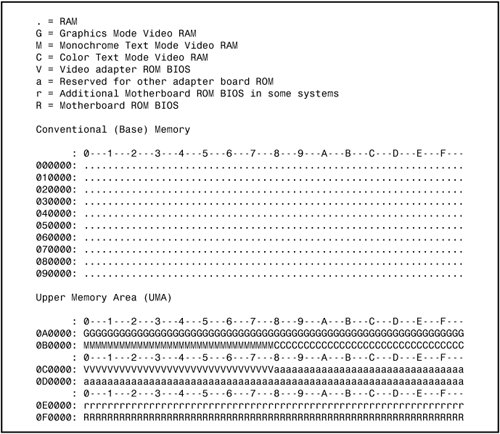 Some think it is strange that the PC would start executing BIOS instructions 16 bytes from the end of the ROM, but this design was intentional. All the ROM programmer has to do is place a JMP (jump) instruction at that address that instructs the processor to jump to the actual beginning of the ROMin most cases, close to F0000hwhich is about 64KB earlier in the memory map. It's like deciding to read every book starting 16 pages from the end and then having all book publishers agree to place an instruction there to jump back the necessary number of pages to get to page 1. By setting the startup location in this way, Intel enabled the ROM to grow to be any size, all the while keeping it at the upper end of addresses in the first megabyte of the memory address space. The main ROM BIOS is contained in a ROM chip on the motherboard, but adapter cards with ROMs contain auxiliary BIOS routines and drivers needed by the particular card, especially for those cards that must be active early in the boot process, such as video cards. Cards that don't need drivers active during boot (such as sound cards) typically don't have a ROM because those drivers can be loaded from the hard disk later in the boot process. Because the BIOS is the main portion of the code stored in ROM, we often call the ROM the ROM BIOS. In older PCs, the motherboard ROM BIOS could consist of up to five or six total chips, but most PCs have required only a single chip for many years now. Adapter card ROMs, such as those used for video, SCSI, add-on ATA cards, and network cards for diskless workstations, are automatically scanned and read by the motherboard ROM during the early part of the boot processduring the POST. The motherboard ROM scans a special area of RAM reserved for adapter ROMs (addresses C0000DFFFFh) looking for 55AAh signature bytes that indicates the start of a ROM. All adapter ROMs must start with 55AAh; otherwise, the motherboard won't recognize them. The third byte indicates the size of the ROM in 512-byte units called paragraphs, and the fourth byte is the actual start of the driver programs. The size byte is used by the motherboard ROM for testing purposes. The motherboard ROM adds all the bytes in the ROM and divides the sum by the number of bytes. The result should produce a remainder of 100h. Thus, when creating a ROM for an adapter, the programmer typically uses a "fill" byte at the end to get the checksum to come out right. Using this checksum, the motherboard tests each adapter ROM during the POST and flags any that appear to have been corrupted. The motherboard BIOS automatically runs the programs in any adapter ROMs it finds during the scan. You see this in most systems when you turn on your system, and during the POST you see the video card BIOS initialize and announce its presence. ROM ShadowingROM chips by their natures are very slow, with access times of 150ns (nanoseconds, or billionths of a second), compared to DRAM access times of less than 10ns on the newest systems. Because of this, in virtually all systems the ROMs are shadowed, which means they are copied into DRAM chips at startup to allow faster access during normal operation. The shadowing procedure copies the ROM into RAM and then assigns that RAM the same address as the ROM originally used, disabling the actual ROM in the process. This makes the system seem as though it has ROM running at the same speed as RAM. The performance gain from shadowing is often very slight, and it can cause problems if not set up properly. Therefore, in most cases, it is wise to shadow only the motherboard (and maybe the video card BIOS) and leave the others alone. Typically, shadowing is useful only if you are running 16-bit operating systems, such as DOS or Windows 3.x. If you are running a 32-bit operating system, such as Windows 9x, Windows Me, Windows 2000, Windows NT, or Windows XP, shadowing is virtually useless because those operating systems do not use the 16-bit ROM code while running. Instead, those operating systems load 32-bit drivers into RAM, which replace the 16-bit BIOS code used only during system startup. Shadowing controls are found in the CMOS Setup program in the motherboard ROM, which is covered in more detail later in this chapter. ROM Chip TypesThe four main types of ROM chips that have been used in PCs are as follows:
No matter which type of ROM your system uses, the data stored in a ROM chip is nonvolatile and remains indefinitely unless intentionally erased or overwritten (in those cases where that is possible). Table 5.1 lists the identifying part numbers typically used for each type of ROM chip, along with any other identifying information.
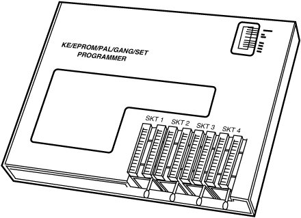
ROM (True or Mask ROM)Originally, most ROMs were manufactured with the binary data (0s and 1s) already "cast in" or integrated into the die. The die represents the actual silicon chip itself. These are called Mask ROMs because the data is formed into the mask from which the ROM die is photolithographically produced. This type of manufacturing method is economical if you are making hundreds of thousands of ROMs with the same information. If you must change a single bit, however, you must remake the mask, which is an expensive proposition. Because of costs and inflexibility, nobody uses Mask ROMs anymore. Mask ROMs are exactly analogous to prerecorded CD-ROMs. Some people think a CD-ROM is first manufactured as a blank and then the data is written to it by a laser, but that is not true. A CD-ROM is literally a piece of plastic that is stamped in a press, and the data is directly molded in, not written. The only actual recording is done with the master disc from which the molds or stamps are made. PROMPROMs are a type of ROM that is blank when new and that must be programmed with whatever data you want. The PROM was invented in the late 1970s by Texas Instruments and has been available in sizes from 1KB (8Kb) to 2MB (16Mb) or more. They can be identified by their part numbers, which usually are 27nnnnwhere the 27 indicates the TI type PROM and the nnnn indicates the size of the chip in kilobits (not bytes). For example, most PCs that used PROMs came with 27512 or 271000 chips, which indicate 512Kb (64KB) or 1Mb (128KB). Note Since 1981, all cars sold in the United States have used onboard computers with some form of ROM containing the control software. For example, my 1989 Pontiac Turbo Trans Am came with an onboard computer containing a 2732 PROM, which was a 32Kb (4KB) chip in the ECM (electronic control module or vehicle computer) under the dash. This chip contained the vehicle operating software as well as all the data tables describing spark advance, fuel delivery, and other engine and vehicle operating parameters. Many devices with integrated computers use PROMs to store their operating programs. Although we say these chips are blank when new, they are technically preloaded with binary 1s. In other words, a 1Mb ROM chip used in a PC would come with 1 million (actually 1,048,576) bit locations, each containing a binary 1. A blank PROM can then be programmed, which is the act of writing to it. This usually requires a special machine called a device programmer, ROM programmer, or ROM burner (see Figure 5.3). Figure 5.3. Typical gang (multisocket) device programmer (PROM burner). Programming the ROM is sometimes referred to as burning it because that is technically an apt description of the process. Each binary 1 bit can be thought of as a fuse, which is intact. Most chips run on 5 volts, but when a PROM is programmed, a higher voltage (normally 12 volts) is placed at the various addresses within the chip. This higher voltage actually blows or burns the fuses at the desired locations, thus turning any given 1 into a 0. Although you can turn a 1 into a 0, you should note that the process is irreversible; that is, you can't turn a 0 back into a 1. The device programmer examines the program you want to write into the chip and then selectively changes only the 1s to 0s where necessary in the chip. PROM chips are often referred to as OTP (one-time programmable) chips for this reason. They can be programmed once and never erased. Most PROMs are very inexpensiveabout $3 for a typical PC motherboard PROMso if you want to change the program in a PROM, you discard it and program a fresh one with the new data. The act of programming a PROM takes anywhere from a few seconds to a few minutes, depending on the size of the chip and the algorithm used by the programming device. Figure 5.3 shows an illustration of a typical PROM programmer that has multiple sockets. This is called a gang programmer and can program several chips at once, saving time if you have several chips to write with the same data. Less expensive programmers are available with only one socket, which is fine for most individual use. I use and recommend a very inexpensive programmer from a company called Andromeda Research Labs (www.arlabs.com). Besides being economical, its unit has the advantage of connecting to a PC via the parallel port for fast and easy data transfer of files between the PC and programming unit. The unit is also portable and comes built into a convenient carrying case. It is operated by a menu-driven program you install on the connected PC. The program contains several features, including a function that enables you to read the data from a chip and save it in a file on your system, as well as write a chip from a data file, verify that a chip matches a file, and verify that a chip is blank before programming begins. A low-cost BIOS backup option makes backing up the flash BIOS chip in your system easy (if it is removable) as a safeguard against disaster.
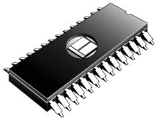
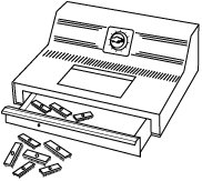
EPROMOne variation of the PROM that has been very popular is the EPROM. An EPROM is a PROM that is erasable. An EPROM chip can be easily recognized by the clear quartz crystal window set in the chip package directly over the die (see Figure 5.4). You can actually see the die through the window! EPROMs have the same 27xxxx part-numbering scheme as the standard PROM, and they are functionally and physically identical except for the clear quartz window above the die. Figure 5.4. An EPROM showing the quartz window for ultraviolet erasing. The purpose of the window is to allow ultraviolet light to reach the chip die because the EPROM is erased by exposure to intense UV light. The window is quartz crystal because regular glass blocks UV light. You can't get a suntan through a glass window! Note The quartz window makes the EPROMs more expensive than the OTP PROMs. This extra expense is needless if erasability is not important. The UV light erases the chip by causing a chemical reaction, which essentially melts the fuses back together. Thus, any binary 0s in the chip become 1s, and the chip is restored to a new condition with binary 1s in all locations. To work, the UV exposure must be at a specific wavelength (2,537 angstroms), at a fairly high intensity (12,000 uw/cm2), in close proximity (2cm3cm, or about 1"), and last for between 5 and 15 minutes duration. An EPROM eraser is a device that contains a UV light source (usually a sunlamp-type bulb) above a sealed compartment drawer in which you place the chip or chips (see Figure 5.5). Figure 5.5. A professional EPROM eraser. Figure 5.5 shows a professional-type EPROM eraser that can handle up to 50 chips at a time. I use a much smaller and less expensive one called the DataRase by Walling Co. This device erases up to four chips at a time and is both economical and portable. The current version is called DataRase II; the DataRase II and similar products are sold by DigiKey (www.digikey.com) and other sources of EPROM programming equipment. The quartz crystal window on an EPROM typically is covered by tape, which prevents accidental exposure to UV light. UV light is present in sunlight, of course, and even in standard room lighting, so that over time a chip exposed to the light can begin to degrade. For this reason, after a chip is programmed, you should put a sticker over the window to protect it. EEPROM/Flash ROMA newer type of ROM is the EEPROM, which stands for electrically erasable PROM. These chips are also called flash ROMs and are characterized by their capability to be erased and reprogrammed directly in the circuit board they are installed in, with no special equipment required. By using an EEPROM, or flash ROM, you can erase and reprogram the motherboard ROM in a PC without removing the chip from the system or even opening up the system chassis. With a flash ROM or EEPROM, you don't need a UV eraser or device programmer to program or erase chips. Not only do virtually all PC motherboards built since 1994 use flash ROMs or EEPROMs, but most automobiles built since then use them as well. For example, my 1994 Chevy Impala SS had a PCM with an integral flash ROM, as do virtually all 1993 and newer vehicles. The EEPROM or flash ROM can be identified by a 28xxxx or 29xxxx part number, as well as by the absence of a window on the chip. Having an EEPROM or a flash ROM in your PC motherboard means you now can easily upgrade the motherboard ROM without having to swap chips. In most cases, you download the updated ROM from the motherboard manufacturer's website and then run a special program it provides to update the ROM. This procedure is described in more detail later in this chapter. I recommend that you periodically check with your motherboard manufacturer to see whether an updated BIOS is available for your system. An updated BIOS might contain bug fixes or enable new features not originally found in your system. You might find fixes for ATA hard drive support over 8.4GB or new drivers to support booting from LS-120 (120MB floppy) drives or USB drives.
These days, many objects with embedded computers controlling them are using flash ROMs. Pretty soon you'll be downloading flash ROM upgrades into your toaster as well!
Many other devices have flash ROMs; for example, I have updated the flash ROM code (often called firmware) in my network routers, wireless access points, and even some digital cameras. Installing flash ROM or firmware upgrades is as easy as downloading a file from the device manufacturer website and running the update program included in the file. Flash ROM updates can also be used to add new capabilities to existing peripherals, such as modems or rewriteable DVD or CD drives, to the latest standards; for example, updating a modem from X2 or K56Flex to V.90 or V.92 or adding support for the latest types of media to a rewriteable drive. ROM BIOS ManufacturersSeveral popular BIOS manufacturers in the market today supply the majority of motherboard and system manufacturers with the code for their ROMs. This section discusses the various available versions. Several companies have specialized in the development of a compatible ROM BIOS product. The three major companies that come to mind in discussing ROM BIOS software are American Megatrends, Inc. (AMI); Phoenix Technologies; and Award Software (now owned by Phoenix Technologies). Each company licenses its ROM BIOS to motherboard manufacturers so those manufacturers can worry about the hardware rather than the software. To obtain one of these ROMs for a motherboard, the original equipment manufacturer (OEM) must answer many questions about the design of the system so that the proper BIOS can be either developed or selected from those already designed. Combining a ROM BIOS and a motherboard is not a haphazard task. No single, generic, compatible ROM exists, either. AMI, Award, Microid Research (MR BIOS), and Phoenix ship many variations of their BIOS code to different board manufacturers, each one custom tailored to that specific motherboard. Over the years, some major changes have occurred in the BIOS industry. Intel, the largest BIOS customer, has gone from using mostly Phoenix to using AMI, back to Phoenix, and now back to AMI for most of its motherboards. Intel originally used the Phoenix BIOS core in its motherboards up through 1995, when it changed to an AMI core. It then used AMI until 1997, when it switched back to Phoenix. In 1999 Intel switched again, this time back to AMI. In all these cases, Intel takes the core BIOS from Phoenix or AMI and highly customizes it for its particular motherboards. It is always a big deal which BIOS Intel uses because Intel manufactures more motherboards than any other company. What that basically means is that if you purchase a PC today, you have a good chance of receiving an Intel-made motherboard with AMI BIOS. Another major development in BIOS occurred in late 1998, when Phoenix bought Award. For several years, Phoenix continued to sell the Award BIOS as a separate product line. However, in March 2002, Phoenix introduced two new product lines based on the previous BIOS. The Phoenix FirstBIOS is based on code from both the Award BIOS and Phoenix BIOS. Currently, the BIOS market is divided between AMI and Phoenix; however, Phoenix not only develops the BIOS for many systems, but is also the primary BIOS developer responsible for new BIOS development and new BIOS standards. Another development in recent years has been the creation of separate BIOS products for 32-bit and 64-bit desktop systems, mobile systems, 32-bit and 64-bit servers, and embedded devices. Although all BIOS chips must perform some of the same tasks, a BIOS product optimized for a mobile computer often needs additional support for features such as docking modules, advanced battery power management, as well as bootable USB and removable Flash memory devices, whereas a BIOS optimized for a server needs support for features such as advanced hardware monitoring and 64-bit PCI slots. By creating customized BIOS versions for different platforms, BIOS vendors provide support for the features needed by a particular computing platform and provide better performance and stability. OEMsAlthough most use either the AMI or Phoenix offerings, some OEMs have developed their own compatible BIOS ROMs independently. Companies such as Compaq, AT&T, and Acer have developed their own BIOS products that are comparable to those offered by AMI and Phoenix. These companies also offer upgrades to newer versions that often can provide more features and improvements or fix problems with the older versions. If you use a system with a proprietary ROM, ensure that it is from a larger company with a track record and one that will provide updates and fixes as necessary. Ideally, upgrades should be available for download from the Internet. Most OEMs have their BIOS written for them by a third-party company. For example, IBM and Hewlett-Packard contract with Phoenix to develop the motherboard BIOS for some HP PCs. Note that even though Phoenix might have done the development, you still must get upgrades or fixes from the OEM. This is really true for all systems because all motherboard manufacturers customize the BIOS for their boards. AMIAlthough AMI customizes the ROM code for a particular system, it does not sell the ROM source code to the OEM. An OEM must obtain each new release as it becomes available. Because many OEMs don't need or want every new version developed, they might skip several version changes before licensing a new one. The AMI BIOS is currently the most popular BIOS in PC systems. Some versions of the AMI BIOS are called Hi-Flex because of the high flexibility found in the BIOS configuration program. The AMI Hi-Flex BIOS products are used in Intel, AMI, and many other manufacturers' motherboards. One special AMI feature is that it is the only third-party BIOS manufacturer to make its own motherboards and other hardware devices. During power up, the BIOS ID string is displayed on the lower-left part of the screen. This string tells you valuable information about which BIOS version you have and about certain settings that are determined by the built-in setup program. Tip A good trick to help you view the BIOS ID string is to shut down and either unplug your keyboard or hold down a key as you power back on. This causes a keyboard error, and the string remains displayed. You also can download the AMI Motherboard ID Utility program (AMIMBID) from AMI's website (www.ami.com/support/mbid.cfm) and run it to determine the contents of ID String 1. The primary BIOS Identification string (ID String 1) is displayed by any AMI BIOS during the POST in the bottom-left corner of the screen, below the copyright message. Two additional BIOS ID strings (ID Strings 2 and 3) can be displayed by the AMI Hi-Flex BIOS by pressing the Insert key during the POST. These additional ID strings display the options installed in the BIOS. The general BIOS ID String 1 format for older AMI BIOS versions is shown in Table 5.2. In addition, the BIOS ID String 1 format for AMI Hi-Flex BIOS versions is shown in Table 5.3, the AMI Hi-Flex BIOS ID String 2 in Table 5.4, and the AMI Hi-Flex BIOS ID String 3 in Table 5.5.
The AMI BIOS has many features, including a built-in setup program activated by pressing the Delete or Esc key in the first few seconds of booting up your computer. The BIOS prompts you briefly as to which key to press and when to press it. The AMI BIOS offers user-definable hard disk types, essential for optimal use of many ATA or ESDI drives. The 1995 and newer BIOS versions also support enhanced ATA drives and autoconfigure the drive parameters. A unique feature of some of the AMI BIOS versions was that in addition to the setup, they had a builtin, menu-driven diagnostics packageessentially a very limited version of the standalone AMIDIAG product. The internal diagnostics are not a replacement for more comprehensive disk-based programs, but they can help in a pinch. The menu-driven diagnostics do not do extensive memory testing, for example, and the hard disk low-level formatter works only at the BIOS level rather than at the controller register level. These limitations often have prevented it from being capable of formatting severely damaged disks. Most newer AMI BIOS versions no longer include the full diagnostics. AMI doesn't produce BIOS documentation; it leaves that up to the motherboard manufacturers who include their BIOS on the motherboard. However, AMI has published a detailed version of its documentation called the Programmer's Guide to the AMIBIOS: Includes Descriptions of PCI, APM, and Socket Services BIOS Functions, published by Windcrest/McGraw-Hill, ISBN 0-07-001561-9. This book, written by AMI engineers, describes all the BIOS functions, features, error codes, and more. Unfortunately, this book is out of print. If you can locate it (try searching with Google or at Amazon.com), I recommend this book for users with an AMI BIOS in their systems because this provides a complete version of the documentation for which they might have been looking. The AMI BIOS is sold through distributors, a list of which is available at its website. However, keep in mind that you can't buy upgrades and replacements directly from AMI, and AMI produces upgrades only for its own motherboards. If you have a non-AMI motherboard with a customized AMI BIOS, you must contact the motherboard manufacturer for an upgrade or use a third-party BIOS upgrade vendor such as those discussed later in this chapter. AwardPhoenix now refers to the family of products that are built on its Award BIOS and Phoenix BIOS designs as FirstBIOS. The FirstBIOS has all the features you expect, including a built-in setup program activated by pressing Ctrl+Alt+Esc or a particular key on startup (usually prompted on the screen). This setup offers user-definable drive types, required to fully use ATA or ESDI hard disks. The POST is good, although the few beep codes supported means that a POST card is necessary if you want to diagnose most power-on problems. Phoenix provides technical support on its website at www.phoenix.com.eSupport.com (formerly Unicore Software) provides limited Award BIOS upgrades for end users. PhoenixThe Phoenix BIOS (now sold by Phoenix as FirstBIOS Pro) for many years has been a standard of compatibility by which others are judged. It was one of the first third-party companies to legally reverse-engineer the IBM BIOS using a clean-room approach. In this approach, a group of engineers studied the IBM BIOS and wrote a specification for how that BIOS should work and what features should be incorporated. This information then was passed to a second group of engineers who had never seen the IBM BIOS. They could then legally write a new BIOS to the specifications set forth by the first group. This work was then unique and not a copy of IBM's BIOS; however, it functioned the same way. The Phoenix (FirstBIOS Pro) BIOS excels in two areas that put it high on my list of recommendations. One is that the POST is excellent. The BIOS outputs an extensive set of beep codes that can be used to diagnose severe motherboard problems that would prevent normal operation of the system. In fact, with beep codes alone, this POST can isolate memory failures in Bank 0 right down to the individual SIMM or DIMM module. The Phoenix BIOS also has an excellent setup program free from unnecessary frills, but one that offers all the features the user would expect, such as user-definable drive types and so on. The built-in setup is activated by pressing Ctrl+Alt+S; Ctrl+Alt+Esc; or a particular key on startup, such as F1 or F2 on most newer systems, depending on the version of BIOS you have. The second area in which Phoenix excels is the documentation. Not only are the manuals you get with the system detailed, but Phoenix has also written a set of BIOS technical reference manuals that are a standard in the industry. The original set consists of three books, titled System BIOS for IBM PC/XT/AT Computers and Compatibles, CBIOS for IBM PS/2 Computers and Compatibles, and ABIOS for IBM PS/2 Computers and Compatibles; an updated version is called System BIOS for IBM PCs, Compatibles, and EISA Computers: The Complete Guide to ROM-Based System Software. In addition to being excellent references for the Phoenix BIOS, these books serve as an outstanding overall reference to the BIOS in general. These are out of print but might be available through bookfinder services such as Amazon.com. Phoenix has extensive technical support and documentation on its website at www.phoenix.com, and you can also find documentation on the eSupport site (www.esupport.com). You also can check the phone numbers listed in the Vendor List on the disc packaged with this book. Micro Firmware and eSupport offer upgrades to some older systems with an AMI or a Phoenix/Award BIOS, including many Packard Bell, Gateway (with Micronics motherboards), Micron Technologies, and other systems. For most systems, especially newer ones, you need to get any BIOS updates from the system or motherboard manufacturer. These companies' products are established as ROM BIOS standards in the industry, and frequent updates and improvements ensure that a system containing these ROMs will have a long life of upgrades and service. Microid Research BIOSMicroid Research (MR) is an interesting BIOS supplier. It primarily markets upgrade BIOS for older Pentium and 486 motherboards that were abandoned by their original manufacturers. As such, it is an excellent upgrade for adding new features and performance to an older system. Tip If you support several BIOS types, consider adding Phil Croucher's The BIOS Companion to your bookshelf or PDF file collection. This book provides detailed BIOS options and configuration information for today's leading BIOS. You can purchase various editions from Amazon.com and other bookstores, but for the most up-to-date (and least expensive) edition, I suggest ordering the PDF (Adobe Acrobat) version of The BIOS Companion from Electrocution.com. | ||||||||||||||||||||||||||||||||||||||||||||||||||||||||||||||||||||||||||||||||||||||||||||||||||||||||||||||||||||||||||||||||||
EAN: 2147483647
Pages: 283