Hardware Elements of Your Network
| The choice of a data-link protocol affects the network hardware you choose. Because Fast Ethernet, Gigabit Ethernet, Wireless Ethernet, and other data-link protocols use different hardware, you must select the architecture before you can select appropriate hardware, including network interface cards, cables, and hubs or switches. Network Interface CardsOn most computers, the network interface adapter takes the form of a network interface card (NIC) that fits into a PCI slot on a desktop computer or a PC Card (PCMCIA) slot on a notebook computer. Although network cards for older systems might use the ISA or EISA slot standards, these don't support high-speed network standards and are obsolete. Many recent systemsboth workstations and serversincorporate the network interface adapter onto the motherboard. Note You can also adapt the USB port for Ethernet use with a USB-to-Ethernet adapter, but because USB 1.1 ports run at only 12Mbps (compared to Fast Ethernet running at 100Mbps), a performance bottleneck results. USB 2.0toFast Ethernet adapters are available from several vendors and are a suitable choice if your system has USB 2.0 ports but lacks a free PCI or PC Card slot. Network adapters have unique hardware addresses coded into their firmware. The data link layer protocol uses these addresses to identify the other systems on the network. A packet gets to the correct destination because its data link layer protocol header contains the hardware addresses of both the sending and receiving systems. Ethernet network adapters range in price from less than $20 for client adapters to as much as $100 or more for server-optimized adapters. Token-Ring adapters, if required, are much more expensive, ranging in price from around $100 for client adapters to more than $500 for server-optimized adapters. Network adapters are built in all the popular interface-card types and are also optimized for either workstation or server use. For first-time network users, so-called network-in-a-box kits are available that contain two 10/100 Fast Ethernet or Wireless NICs (or PC Cards), a small switch, and prebuilt UTP cables for less than $100. When combined with the built-in networking software in Windows, these kits make networking very inexpensive. A number of 100/1000-BASE-TX Gigabit Ethernet adapters for use with UTP cable can be purchased for less than $60, and many switches now also feature Gigabit Ethernet ports. For client workstations (including peer servers on peer-to-peer networks), the following sections contain my recommendations on the features you need. SpeedYour NIC should run at the maximum speed you want your network to support. For a Gigabit Ethernet network, for example, you should purchase Ethernet cards that support 1000BASE-T's 1000Mbps speed. Most Gigabit Ethernet and Fast Ethernet cards also support slower speeds, such as Fast Ethernet's 100Mbps speed or standard Ethernet's 10Mbps speed, allowing the same card to be used on both older and newer portions of the network. To verify multispeed operation, look for network cards identified as 10/100 or 100/1000 Ethernet. In the case of wireless networking in the home, your best option remains 802.11g. Your NIC should support both half-duplex and full-duplex operation:
Unlike hubs, which broadcast data packets to all computers connected to it, switches create a direct connection between the sending and receiving computers. Thus, switches provide faster performance than hubs; most switches also support full-duplex operation, doubling the rated speed of the network when full-duplex network cards are used. Bus TypeIf you are networking desktop computers built from 1995 to the present, you should consider only PCI-based NICs (these computers typically have three or more PCI slots). Although many older computers still have at least one ISA or combo ISA/PCI expansion slot, the superior data bus width and data transfer rate of PCI make it the only logical choice for networks of all types. The integrated NIC found on most recent PC motherboards is also a PCI device. Alternative interfaces include USB or PC Card/Cardbus adapters that are often used for portable systems. At this time, there are also a handful of NICs based on PCI Express. Table 18.3 summarizes the differences between all the types of interfaces network cards use.
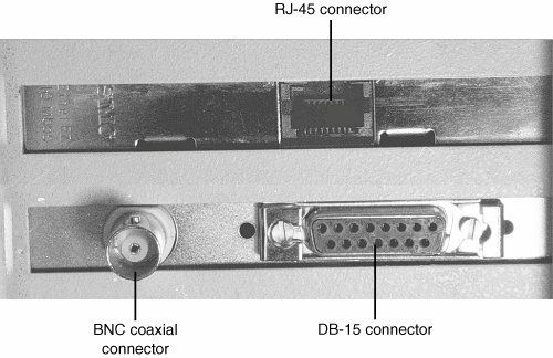
Although a few ISA-based NICs are still on the market, their slow speeds and narrow bus widths severely restrict their performance. Most ISA-based Ethernet cards can't support speeds above 10Mbps and thus don't support Fast Ethernet or Gigabit Ethernet. A few vendors make 10/100 Ethernet cards for the ISA slot, but their performance is substantially lower than PCI cards. If you are shopping for a network card for a laptop or notebook system, look for Cardbus types, which are significantly faster than PC Cards and those using USB. Wired Network Adapter ConnectorsWired Ethernet adapters typically have an RJ-45 connector, which looks like a large telephone jack. Fast Ethernet and Gigabit Ethernet twisted-pair cables use these connectors, but you might still find a few older adapters that support a single BNC connector (for Thinnet coaxial cables), or a D-shaped 15-pin connector called a DB15 (for Thicknet coaxial cables). A few older 10Mbps adapters have a combination of two or all three of these connector types; adapters with two or more connectors are referred to as combo adapters. Token-Ring adapters can have a 9-pin connector called a DB9 (for Type 1 STP cable) or sometimes an RJ-45 jack (for Type 3 UTP cable). Figure 18.5 shows all three of the Ethernet connectors. Figure 18.5. Three Ethernet connectors on two NICs: RJ-45 connector (top center), DB-15 connector (bottom right), and BNC connector (bottom left). Virtually all 10/100 Ethernet NICs made for client-PC use on the market today are designed to support unshielded twisted-pair (UTP) cable exclusively; Gigabit Ethernet cards made for wired (not fiber-optic) networks also use only UTP cable. If you are adding a client PC to an existing network that uses some form of coaxial cable, you have four options:
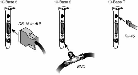
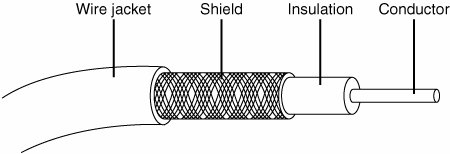
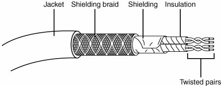
For maximum economy, NICs and network cables must match, although media converters can be used to interconnect networks based on the same standard, but using different cable. Network Cables for Wired EthernetOriginally, all networks used some type of cable to connect the computers on the network to each other. Although various types of wireless networks are now on the market, many office and home networks still use twisted-pair Ethernet cabling. Occasionally you might still find some based on Thick or Thin Ethernet coaxial cable. Thick and Thin Ethernet Coaxial CableThe first versions of Ethernet were based on coaxial cable. The original form of Ethernet, 10BASE-5, used a thick coaxial cable (called Thicknet) that was not directly attached to the NIC. A device called an attachment unit interface (AUI) ran from a DB15 connector on the rear of the NIC to the cable. The cable had a hole drilled into it to allow the "vampire tap" to be connected to the cable. NICs designed for use with thick Ethernet cable are almost impossible to find as new hardware today. 10BASE-2 Ethernet cards use a BNC (Bayonet-Neill-Concilman) connector on the rear of the NIC. Although the thin coaxial cable (called Thinnet or RG-58) used with 10BASE-2 Ethernet has a bayonet connector that can physically attach to the BNC connector on the card, this configuration is incorrect and won't work. Instead, a BNC T-connector attaches to the rear of the card, allowing a thin Ethernet cable to be connected to either both ends of the T (for a computer in the middle of the network) or to one end only (for a computer at the end of the network). A 50-ohm terminator is connected to the other arm of the T to indicate the end of the network and prevent erroneous signals from being sent to other clients on the network. Some early Ethernet cards were designed to handle thick (AUI/DB15), thin (RG-58), and UTP (RJ-45) cables. Combo cards with both BNC and RJ-45 connectors may still be available but can run at only standard Ethernet speeds. Figure 18.6 compares Ethernet DB-15 to AUI, BNC coaxial T-connector, and RJ-45 UTP connectors to each other, and Figure 18.7 illustrates the design of coaxial cable. Figure 18.6. An Ethernet network card with thick Ethernet (DB-15), thin Ethernet (RG-58 with T-connector), and UTP (RJ-45) connectors. Figure 18.7. Coaxial cable. Twisted-Pair CableTwisted-pair cable is just what its name implies: insulated wires within a protective casing with a specified number of twists per foot. Twisting the wires reduces the effect of electromagnetic interference (that can be generated by nearby cables, electric motors, and fluorescent lighting) on the signals being transmitted. Shielded twisted pair (STP) refers to the amount of insulation around the cluster of wires and therefore its immunity to noise. You are probably familiar with unshielded twisted-pair (UTP) cable; it is often used for telephone wiring. Figure 18.8 shows unshielded twisted-pair cable; Figure 18.9 illustrates shielded twisted-pair cable. Figure 18.8. An unshielded twisted-pair (UTP) cable. Figure 18.9. A shielded twisted-pair (STP) cable.
Most Ethernet and Fast Ethernet installations that use twisted-pair cabling use UTP because the physical flexibility and small size of the cable and connectors makes routing it very easy. However, its lack of electrical insulation can make interference from fluorescent lighting, elevators, and alarm systems (among other devices) a major problem. If you use UTP in installations where interference can be a problem, you need to route the cable away from the interference, use an external shield, or substitute STP for UTP near interference sources. Four standard types of unshielded twisted-pair cabling exist and are still used to varying degrees:
Caution If you choose to install Category 5/5e UTP cable, be sure that all the connectors, wall plates, and other hardware components involved are also Category 5rated. If you are trying to connect prebuilt Category 5 cabling together on a Fast Ethernet network, use Category 5grade or better connectors; otherwise, you'll create a substandard section that might fail in your network. Choosing the correct type of Category 5/5e/6/7 cable is also important. Use solid PVC cable for network cables that represent a permanent installation. However, the slightly more expensive stranded cables are a better choice for a notebook computer or temporary wiring of no more than 10-feet lengths (from a computer to a wall socket, for example) because it is more flexible and is therefore capable of withstanding frequent movement. If you plan to use air ducts or suspended ceilings for cable runs, you should use Plenum cable, which doesn't emit harmful fumes in a fire. It is much more expensive, but the safety issue is a worthwhile reason to use it (some localities require you to use Plenum cabling). Building Your Own Twisted-Pair CablesWhen it's time to wire your network, you have two choices. You can opt to purchase prebuilt cables, or you can build your own cables from bulk wire and connectors. You should build your own twisted-pair cables if you
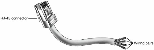
Twisted Pair Wiring StandardsIf you want to create twisted-pair (TP) cables yourself, be sure your cable pairs match the color-coding of any existing cable or the color-coding of any prebuilt cabling you want to add to your new network. Because there are eight wires in TP cables, many incorrect combinations are possible. Several standards exist for UTP cabling. Tip The keys are to be consistent, use the same scheme for all your cables, and ensure that anyone else working on your network understands the scheme used in it. One common standard is the AT&T 258A configuration (also called EIA/TIA 568B). Table 18.4 lists the wire pairing and placement within the standard RJ-45 connector.
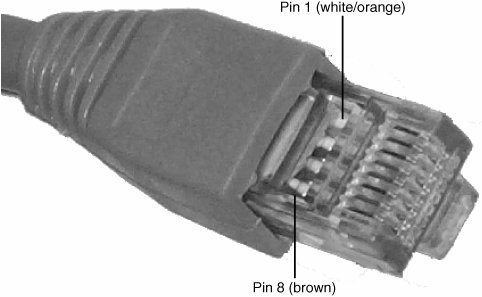
In Figure 18.11 an RJ-45 cable connector is wired to the AT&T 258A/EIA 568B standard. Figure 18.11. An AT&T 258A/EIA 568B standard compliant RJ-45 connector. Note You also might encounter the similar EIA 568A standard. It reverses the position of the orange and green pairs listed previously. Crossover UTP CablesCrossover cables, which change the wiring at one end of the cable, are used to connect two (and only two) computers when no hub or switch is available or to connect a hub or switch without an uplink port to another hub or switch. The pinout for a crossover cable is shown in Table 18.5. This pinout is for one end of the cable only; the other end of the cable should correspond to the standard EIA 568B pinout, as shown previously in Figure 18.11.
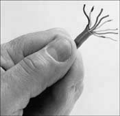
Note It should be noted that other wiring schemes exist, such as IEEE and USOC. All told, at least eight agreed-on standards exist for connecting UTP cables and RJ-45 connectors. The ones listed in this chapter are the most common. Constructing the CableMaking your own UTP cables requires a few tools that aren't commonly found in a typical toolbox. Those items that you might not already have you can typically purchase for a single price from many network-products vendors. You will need the following tools and supplies to build your own Ethernet cables:
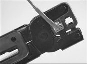
Before you make a "real" cable of any length, you should practice on a short length of cable. RJ-45 connectors and bulk cable are cheap; network failures are not. Follow these steps for creating your own twisted-pair cables:
The cables should be labeled at both ends to make matching the cable with the correct computer easy and to facilitate troubleshooting at the hub. Check with your cable supplier for suitable labeling stock or tags you can attach to each cable. Cable Distance LimitationsThe people who design computer systems love to find ways to circumvent limitations. Manufacturers of Ethernet products have made possible the building of networks in star, branch, and tree designs that overcome the basic limitations already mentioned (for more information, see the "Network Topologies" section later in this chapter). Strictly speaking, you can have thousands of computers on a complex Ethernet network. LANs are local because the network adapters and other hardware components typically can't send LAN messages more than a few hundred feet. Table 18.6 lists the distance limitations of various types of LAN cable. In addition to the limitations shown in the table, keep the following points in mind:
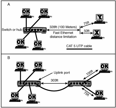
If you have a station wired with Category 5 cable that is more than 328 feet (100 meters) from a hub, you must use a repeater. If you have two or more stations beyond the 328 feet limit of UTP Ethernet, connect them to a hub or switch that is less than 328 feet away from the primary hub or switch and connect the new hub or switch to the primary hub or switch via its uplink port. Because hubs and switches can act as repeaters, this feature enables you to extend the effective length of your network (see Figure 18.16).
Figure 18.16. In case A (top), the workstations on the right are too far away from the hub to connect to a Fast Ethernet network. In case B (bottom), an additional hub or switch is used to allow the workstations to be added to the network. Network TopologiesEach computer on the network is connected to the other computers with cable (or some other medium, such as wireless using radio frequency signals). The physical arrangement of the cables connecting computers on a network is called the network topology. Over the last 15 years the three types of basic topologies used in computer networks have been as follows:
For a long while, these different topologies were often mixed, forming what is called a hybrid network. For example, you can link the hubs of several star networks together with a bus, forming a star-bus network. Rings can be connected in the same way. Table 18.7 summarizes the relationships between network types and topologies.
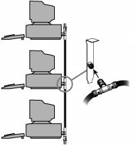
The bus, star, and ring topologies are discussed in the following sections. Wireless networking, which technically doesn't have a physical topology as described here, does still employ two logical (virtual) topologies, which I discuss here as well. Bus TopologyThe earliest type of network topology was the bus topology, which uses a single cable to connect all the computers in the network to each other, as shown in Figure 18.17. This network topology was adopted initially because running a single cable past all the computers in the network is easier and less wiring is used than with other topologies. Because early bus topology networks used bulky coaxial cables, these factors were important advantages. Both 10BASE-5 (thick) and 10BASE-2 (thin) Ethernet networks are based on the bus topology. Figure 18.17. A 10BASE-2 network is an example of a linear bus topology, attaching all network devices to a common cable. However, the advent of cheaper and more compact unshielded twisted-pair cabling, which also supports faster networks, has made the disadvantages of a bus topology apparent. If one computer or cable connection malfunctions, it can cause all the stations beyond it on the bus to lose their network connections. Thick Ethernet (10BASE-5) networks often fail because the vampire tap connecting the AUI device to the coaxial cable comes loose. In addition, the T-adapters and terminating resistors on a 10BASE-2 Thin Ethernet network can also come loose or be removed by the user, causing all or part of the network to fail. Another drawback of Thin Ethernet (10BASE-2) networks is that adding a new computer to the network between existing computers might require replacement of the existing network cable between the computers with shorter segments to connect to the new computer's network card and T-adapter, thus creating downtime for users on that segment of the network. Ring TopologyAnother topology often listed in discussions of this type is a ring, in which each workstation is connected to the next and the last workstation is connected to the first again (essentially a bus topology with the two ends connected). Two major network types use the ring topology:
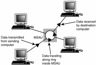
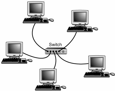
A Token-Ring network resembles a 10BASE-T or 10/100 Ethernet network at first glance because both networks use a central connecting device and a physical star topology. Where is the "Ring" in Token-Ring? The ring exists only within the device that connects the computers, which is called a multistation access unit (MSAU) on a Token-Ring network (see Figure 18.18). Figure 18.18. A Token-Ring network during the sending of data from one computer to another. Signals generated from one computer travel to the MSAU, are sent out to the next computer, and then go back to the MSAU again. The data is then passed to each system in turn until it arrives back at the computer that originated it, where it is removed from the network. Therefore, although the physical wiring topology is a star, the data path is theoretically a ring. This is called a logical ring. A logical ring that Token-Ring networks use is preferable to a physical ring network topology because it affords a greater degree of fault tolerance. As on a bus network, a cable break anywhere in a physical ring network topology, such as FDDI, affects the entire network. FDDI networks use two physical rings to provide a backup in case one ring fails. By contrast, on a Token-Ring network, the MSAU can effectively remove a malfunctioning computer from the logical ring, enabling the rest of the network to function normally. Star TopologyBy far the most popular type of topology in use today has separate cables to connect each computer to a central wiring nexus, often called a switch or hub. Figure 18.19 shows this arrangement, which is called a star topology. Figure 18.19. The star topology, linking the LAN's computers and devices to one or more central hubs, or access units. Because each computer uses a separate cable, the failure of a network connection affects only the single machine involved. The other computers can continue to function normally. Bus cabling schemes use less cable than the star but are harder to diagnose or bypass when problems occur. At this time, Fast Ethernet in a star topology is the most commonly implemented type of LAN; this is the type of network you build with most preconfigured wired networking kits. 10BASE-T Ethernet and 1000BASE-TX Gigabit Ethernet also use the star topology. Wireless Network Logical TopologiesWireless networks have different topologies, just as wired networks do. However, wireless networks use only two logical topologies:
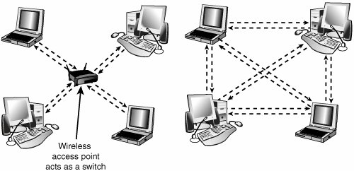
Figure 18.20 shows a comparison of wireless networks using these two topologies. Figure 18.20. A logical star topology (left) as used by IEEE 802.11based wireless Ethernet in infrastructure mode compared to a point-to-point topology as used by Bluetooth and 802.11 in ad hoc mode (right). Hubs and Switches for Ethernet NetworksAs you have seen, modern Ethernet workgroup networkswhether wireless or wired with UTP cableare usually arranged in a star topology. The center of the star uses a multiport connecting device that can be either a hub or a switch. Although hubs and switches can be used to connect the networkand can have several features in commonthe differences between them are also significant and are covered in the following sections. All Ethernet hubs and switches have the following features:
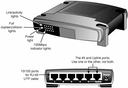
Ethernet hubs and switches are made in two forms: managed and unmanaged. Managed hubs and switches can be directly configured, enabled or disabled, or monitored by a network operator and are commonly used on corporate networks. Workgroup and home-office networks use less expensive unmanaged hubs, which simply connect computers on the network using the systems connected to it to provide a management interface for its configurable features. Note The now-obsolete ARCnet network used its own types of hubs: passive hubs, which were unpowered, and active hubs, which used a power supply. Neither type of hub is compatible with Ethernet. Signal lights on the front of the hub or switch indicate which connections are in use by computers; switches also indicate whether a full-duplex connection is in use. Multispeed hubs and switches also indicate which connection speed is in use on each port. Your hub or switch must have at least one RJ-45 UTP connector for each computer you want to connect to it. How Hubs WorkA computer on an Ethernet network broadcasts (sends) a request for network information or programs from a specific computer through the cable to the hub, which broadcasts the request to all computers connected to it. When the destination computer receives the message, it sends the requested information back to the hub, which broadcasts it again to all computers, although only the requesting computer acts on the information. Thus, a hub acts similarly to a radio transmitter and receiver that sends a signal to all radios, but only the radios set for the correct station can send or receive the information. Switches, due to the features explained in the next section, have largely replaced hubs on retail store shelves. How Switches Differ from HubsSwitches, as shown in Figure 18.21, are similar to hubs in both form factor and function. As with hubs, they connect computers on an Ethernet network to each other. However, instead of broadcasting data to all computers on the network as hubs do, switches use a feature called address storing, which checks the destination for each data packet and sends it directly to the computer for which it's intended. Thus, a switch can be compared to a telephone exchange, making direct connections between the originator of a call and the receiver. Figure 18.21. Front (top) and rear (bottom) of a typical five-port, 10/100 Ethernet switch. Because switches establish a direct connection between the originating and receiving PC, they also provide the full bandwidth of the network to each port. Hubs, by contrast, must subdivide the network's bandwidth by the number of active connections on the network, meaning that bandwidth rises and falls depending on network activity. For example, assume you have a four-station network workgroup using 10/100 NICs and a Fast Ethernet hub. The total bandwidth of the network is 100Mbps. However, if two stations are active, the effective bandwidth available to each station drops to 50Mbps (100Mbps divided by 2). If all four stations are active, the effective bandwidth drops to just 25Mbps (100Mbps divided by 4)! Add more active users, and the effective bandwidth continues to drop. By replacing the hub with a switch, the effective bandwidth for each station remains 100Mbps because the switch doesn't broadcast data to all stations. Most 10/100 NICs and Fast Ethernet or 10/100 switches also support full-duplex (simultaneous transmit and receive), enabling actual bandwidth to be double the nominal 100Mbps rating: 200Mbps. Table 18.8 summarizes the differences between the two devices.
As you can see, using a switch instead of a hub greatly increases the effective speed of a network, even if all other components remain the same. Because of the improved performance of switches, I recommend them instead of hubs for networks of any size. When it comes time to purchase a hub or switch, you'll often find that the price difference is negligible between the two, so the switch makes good economic sense as well. Additional Hub and Switch Features You Might NeedAlthough older hubs and switches run at only a single speed and have only a few RJ-45 connectors, it makes sense to upgrade to newer, more flexible equipment. Most recent hubs and switches have the following useful features, which are worth asking for:
To determine whether a hub or switch is stackable, look for an uplink port. This port looks like an ordinary RJ-45 UTP port, but it is wired differently, enabling you to use a standard-pinout RJ-45 UTP cable to connect it to another hub. Without the uplink port, you'd have to use a specially wired crossover cable. Note The uplink port on your hub or switch is also used to connect the hub or switch to a router or gateway device that provides an Internet connection for your network. In cases where multiple hubs or switches are to be used, they are usually connected directly to the router or gateway instead of chained (or stacked) off each other. Typically, hubs and switches with an uplink port allow you to use the port along with all but one of the normal ports on the hub. For example, one of my associates uses a five-port switch from Linksys that also contains a router (for Internet access) and an uplink port. If his office network expands beyond five computers, he can use the uplink port to add another switch to expand the network and provide the new stations, as well as the original network, with Internet access. Hub and Switch PlacementAlthough large networks have a wiring closet near the server, the workgroup-size LANs found in a small office or home office network obviously don't require anything of the sort. However, the location of the hub or switch is important, even if your LAN is based solely on a Wi-Fi architecture. Ethernet hubs and switches require electrical power, whether they are small units that use a power "brick" or larger units that have an internal power supply and a standard three-prong AC cord. In addition to electrical power, consider placing the hub or switch where its signal lights will be easy to view for diagnostic purposes and where its RJ-45 connectors can be reached easily. This is important both when it's time to add another user or two and when you need to perform initial setup of the switch (requiring a wired connection) or need to troubleshoot a failed wireless connection. In many offices, the hub or switch sits on the corner of the desk, enabling the user to see network problems just by looking at the hub or switch. If the hub or switch also integrates a router for use with a broadband Internet device, such as a DSL or cable modem, you can place it near the cable or DSL modem or at a distance if the layout of your home or office requires it. Because the cable or DSL modem usually connects to your computer by the same Category 5 cable used for UTP Ethernet networking, you can run the cable from the cable or DSL modem to the router/switch's WAN port and connect all the computers to the LAN ports on the router/switch. Except for the 328-ft. (100-meter) limit for all forms of UTP Ethernet (10BASE-T, 100BASE-TX, and 1000BASE-TX), distances between each computer on the network and the hub or switch aren't critical, so put the hub or switch wherever you can supply power and gain easy access. Although wireless networks do offer more freedom in terms of placing the switch/access point, you should keep in mind the distances involved (generally up to 150 feet indoor for 802.11b/g) and any walls or devices using the same 2.4GHz spectrum that might interfere with the signal. Tip Decide where you plan to put your hub or switch before you buy prebuilt UTP wiring or make your own; if you move the hub or switch, some of your wiring will no longer be the correct length. Although excess lengths of UTP cable can be coiled and secured with cable ties, cables that are too short should be replaced. You can buy RJ-45 connectors to create one long cable from two short cables, but you must ensure the connectors are Category 5 if you are running Fast Ethernet; some vendors still sell Category 3 connectors that support only 10Mbps. You're really better off replacing the too-short cable with one of the correct length. More on Wireless Ethernet HardwareAll types of 802.11 wireless networks have two basic components:
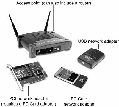
An access point is a bookend-size device that uses one or more RJ-45 ports to attach to a 10BASE-T or 10/100 Ethernet network (if desired) and contains a radio transceiver, encryption, and communications software. It translates conventional Ethernet signals into wireless Ethernet signals that it broadcasts to wireless NICs on the network and then performs the same role in reverse to transfer signals from wireless NICs to the conventional Ethernet network. For coverage of a large area, purchase two or more access points and connect them to an Ethernet switch or hub. This enables users to roam inside a building without losing contact with the network. Some access points can communicate directly with each other via radio waves, enabling you to create a wireless backbone that can cover a wide area (such as a warehouse) without the need to run any network cabling. You can also purchase a wireless Ethernet range extender that can receive and boost weak Wi-Fi signals. Access points are not necessary for direct peer-to-peer networking (also called ad hoc mode), but they are required for a shared Internet connection or a connection with another network. When access points are used, the network is operating in the infrastructure mode. NICs equipped for wireless Ethernet communications have a fixed or detachable radio antenna. Because a major market for wireless Ethernet use is notebook computer users, a few vendors sell only PC Cards in their wireless Ethernet product lines, but most vendors support PCI cards for desktop computers. Most vendors also offer wireless USB adapters for use in both desktop and notebook computers. Because you can mix and match Wi-Ficertified products that use the same frequency band, you can incorporate any mix of desktop and notebook computers into your wireless network. Figure 18.22 illustrates typical wireless network hardware. Figure 18.22. A typical family of Wi-Fi 2.4GHz band (802.11b) wireless products, including a wireless access point, USB, PC Card, and PCI wireless network adapters. The PC Card is used in notebook computers that lack Wi-Fi support and acts as the transceiver for the PCI card used in desktop computers. Photos courtesy of Linksys. In cases where a Wi-Fienabled system receives multiple Wi-Fi signals, client systems lock onto the strongest signal from access points and automatically roam (switch) to another access point when the signal strength is stronger and the error level is lower than the current connection. Of course, if you want the system to lock onto a specific signal, that can be done via the OS or manufacturer-provided software. Additional hardware you might need to add to your network includes
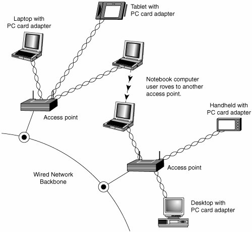
Security and Other FeaturesWhen I was writing the original edition of Upgrading and Repairing PCs, the hackers' favorite way of trying to get into a network without authorization was discovering the telephone number of a modem on the network, dialing in with a computer, and guessing the password, as in the movie War Games. Today, war driving has largely replaced this pastime as a popular hacker sport. War driving is the popular name for driving around neighborhoods with a notebook computer equipped with a wireless network card on the lookout for unsecured networks. They're all too easy to find, and after someone gets onto your network, all the secrets in your computer can be theirs for the taking. Because wireless networks can be accessed by anyone within signal range who has a NIC matching the same IEEE standard of that wireless network, wireless NICs and access points provide for encryption options. Most access points (even cheaper SOHO models) also provide the capability to limit connections to the access point by using a list of authorized MAC numbers (each NIC has a unique MAC), thus limiting access to authorized devices only. Caution In the past, it was thought that the SSID feature provided by the IEEE 802.11 standards was also a security feature. That's not the case. A Wi-Fi network's SSID is nothing more than a network name for the wireless network, much the same as workgroups and domains have network names that identify them. The broadcasting of the SSID can be turned off (when clients look for networks, they won't immediately see the SSID), which does provide a marginal security benefit. However, in general, the SSID should never be considered to be a security item in any way. In fact, many freely available (and quite powerful) tools exist that allow snooping individuals to quickly discover your SSID even if it's not being broadcast, allowing them to connect to your unsecured wireless network. All Wi-Fi products support at least 40-bit encryption through the wired equivalent privacy (WEP) specification, but the minimum standard on recent products is 64-bit WEP encryption. Many vendors offer 128-bit or 256-bit encryption on some of their products. However, the 128-bit and stronger encryption feature is more common among enterprise products than small-office/home-officeoriented products. Unfortunately, the WEP specification has been shown to be notoriously insecure against determined hacking. Enabling WEP will keep a casual snooper at bay, but someone who wants to get into your wireless network won't have much trouble breaking WEP. For that reason, all wireless network products introduced after 2003 incorporate a different security standard known as Wi-Fi Protected Access (WPA). WPA is derived from the developing IEEE 802.11i security standard. WPA-enabled hardware works with existing WEP-compliant devices, and software upgrades are often available for existing devices to make them WPA capable. You should match the encryption level and encryption type used on both the access points and the NICs for best security. Remember that, if some of your network supports WPA but other parts support only WEP, your network must use the lesser of the two security standards (WEP). If you want to use the more robust WPA security, you must ensure that all the devices on your wireless network support WPA. Because WEP is easily broken and the specific WEP implementations vary between manufacturers, I recommend using only devices that support WPA. Some products' access points can be managed via a web browser and provide diagnostic and monitoring tools to help you optimize the positioning of access points. Most products feature support for Dynamic Host Configuration Protocol (DHCP), allowing a user to move from one subnet to another without difficulties. Figure 18.23 illustrates how a typical IEEE 802.11 wireless network uses multiple access points. Figure 18.23. A typical wireless network with multiple access points. As users with wireless NICs move from one office to another, the roaming feature of the NIC automatically switches from one access point to another, permitting seamless network connectivity without wires or logging off the network and reconnecting. Users per Access PointThe number of users per access point varies with the product; Wi-Fi access points are available in capacities supporting anywhere from 15 to as many as 254 users. You should contact the vendor of your preferred Wi-Fi access point device for details. Although wired Ethernet networks are still the least expensive network to build if you can do your own wiring, Wi-Fi networking is now cost-competitive with wired Ethernet networks when the cost of a professional wiring job is figured into the overall expense. Because Wi-Fi is a true standard, you can mix and match access point and wireless NIC hardware to meet your desired price, performance, and feature requirements for your wireless network, just as you can for conventional Ethernet networks provided you match up frequency bands or use dual-band hardware. Notebook Computers with Integrated Wi-Fi AdaptersMajor notebook computer makers, including Dell, IBM, and Toshiba, are now integrating built-in 802.11b/g or 802.11a/b/g wireless adapters and antennas into most of their notebook computers. Although computers with built-in Wi-Fi hardware are a little more expensive than comparable models lacking Wireless Ethernet support, building the adapter and antenna into notebook computers provides for a more durable and less cumbersome way to equip portable systems than the normal PC Card and external antenna arrangement that must be fitted to notebook computers that don't have internal Wi-Fi support. Most notebook computers with Wi-Fi hardware onboard use the mini-PCI interface for the wireless adapter and place the antenna inside the screen housing. This enables computers with built-in Wi-Fi hardware to have one more open PC Card slot than computers that must use an external PC Card adapter and antenna. | ||||||||||||||||||||||||||||||||||||||||||||||||||||||||||||||||||||||||||||||||||||||||||||||||||||||||||||||||||||||||||||||||||||||||||||||||||||||||||||||||||||||||||||||||||||||||||||||||||||||||||||||||||||

EAN: 2147483647
Pages: 283