The Planning Phase
| The sad truth is that no matter where you locate your equipment, each location has issues with temperature, humidity, access, and other factors that are unique for that location and must be planned for. The important task, therefore, is to recognize what issues you face and build solutions for those problems into your design. These are the essential issues you must plan for with any installation:
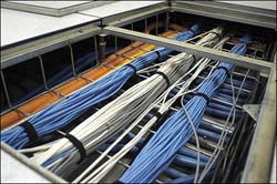
When you have a design in mind and have a plan drawn up, if you are building a new building or an extension to an existing business, you should check with the local government to ensure that all your plans are within the requirements of the local building codes. The approval process requires that you get two levels of approval: one for the design plans and the second for the completed project. You should also check with your insurance company to determine whether the room or building you are planning alters your coverage in any way. Determining Size and CapacityThe size of your server room or data center is a gating factor in the type and distribution of equipment you can employ there. Bigger rooms offer the advantages of more space and potentially lower server density, but they also require correspondingly more facilities, such as HVAC. When they are properly designed, you can also get better airflow with bigger spaces, albeit at a higher cost. A good place to begin laying out the design of a server room is with a design tool such as Visio. When you have the room size and shape laid out on your design surface, you can start to add room features, such as doors and windows, structural columns, and any other features that might affect where you place your system components. Visio contains a number of stencils that provide standard shapes of equipment types, and you can purchase third-party stencils of server room equipment. Figure 17.1 shows some of the stencils dedicated to network and server room design in Visio. Figure 17.1. Visio, which has many dedicated equipment stencils, is a great tool for developing a space plan for a server room. You can also purchase third-party shape libraries of common server room equipment.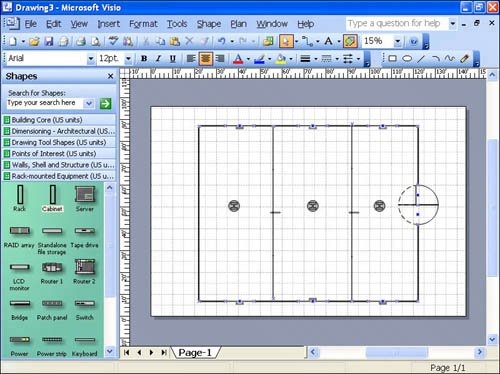 The next step in designing the room is to subdivide the room into squares the size of the server racks that you intend to deploy. Your grid squares can be the size of the panels used in your raised flooring as shown in Figure 17.2, or they can be a standard size, such as 3 feet by 3 feet, which is close to the size of a small server rack. Figure 17.2. Shown here is raised flooring with bundled networking cable. You need to create rows of servers on your design surface, and between the tows should be open aisles that are as wide as each equipment row. It's possible to use as little as 40% open aisle space and 60% equipment row space, but it's much better to have an equal size, so you have some leeway for accommodating oversized equipment if you decide to deploy some at any point.
Bob Snevely, in his book Enterprise Data Center Design and Methodology, ISBN 0130473936, which is part of the Sun Microsystems Blueprints series, developed the concept of rack location units (RLUs). An RLU assigns a weighting factor to the total requirements of the components of a rack system, with respect to the following demands:
The idea behind this approach is that you want to distribute dense server racks across the server room so that you don't overload the capacity of any one section with respect to any of the aforementioned factors. Let's say that you have a section of five server racks aligned side-by-side in a row. In this scenario, you would need to create a table that combined all five of those servers into one set of requirements, such as the following:
With all these measurements in hand, you can then sum them all to create a superset RLU that defines the assemblage. Your five racks might have the following specifications, among others:
If any one particular area can't support these requirements, you should move a dense server out of the group and place it somewhere else. To simplify the process of mixing and matching racks, you might assign a label to the different types of racks and use that label to balance your design. You could assign weighting factors to each requirement, such that your label might be RLU-142331, where each number is the overall assignment of each factor. When you sum five different RLUs, you get a composite number that lets you determine whether you have distributed servers appropriately. Sneveley's assignment uses a simpler scheme of RLA-A, RLA-B, and so forth, but it's possible and probably preferable to extend this idea to make it a little more quantitative. The total RLUs determine what is called the "in-feed capacities" of the system. This total is not the complete story, of course. Your calculations need to account for not only the amounts of each resource but their types as well. Planning for Cable ManagementChapter 16, "Server Racks and Blades," briefly touches on the number of cables that run in and out of dense server racks. As you may recall, a server rack with 24 servers can have from 200 to 250 cables going into the connections at the back of the server. Without some form of organization and identification, it can become impossible to find a broken connection or modify your current connections. The rules for cable management are few:
In a disorganized system, changes that should take seconds can take many minutes, if it's possible to effect the change at all. Without cable management, you can have a rat's nest of wires that impedes airflow and can be a hazard. If you want to know how professional an IT organization is, one of the simplest ways to tell is to look at its cable management scheme on the back of its servers. The simplest cable management systems are those that have a hook or basket arrangement. One site that offers a number of cable management solutions is Cableorganizer.com (www.cableorganizer.com). You can install cable management systems above head height and out of the way. Many server racks come with cable management systems that run at the top of the server rack, as you can see in the APC InfraStruXure rack series shown later in this chapter, in Figure 17.5. If you install a raised floor (see "Considering Raised Flooring," later in this chapter), you are likely to install cable trays as part of your floor support. Cable trays are U-shaped wire baskets onto which the wire is placed. Cable trays are placed so that the wires run parallel to the aisles, thus allowing you to have access to the trays at any point along the run. Determining Power NeedsElectrical consumption is one of the metrics that you need to plan for. As a general rule, you should figure on about 50 watts of power per square foot for a small server to as much as 100 watts per square foot for denser deployments. In addition to specifying the individual rack power requirements, you also need to specify the total room's power needs. For 10 racks, that figure would be 720 amps. Of course, other equipment in a server room can significantly draw on power. Among the larger consumers of power in a server room are HVAC, switches, printers, lighting, and UPS devices. Therefore, you should consider all those factors when allowing for your power requirements. If you have a server rack with 36 1U servers in it, and you figure that each server draws approximately 2 amps, then one rack would consume 72 amps. Current power consumption for servers is averaging over 90% of the server's stated load. Given that you want extra capacity for a rack of this type, you might want to allow for twice the amount of amperage during power burstssay, 150 ampsbecause most racks include other devices, such as arrays, tape backups, rack ventilation, and so forth. Note Large power lines generate magnetic fields that can be a problem for network communications. You need to shield any large power lines so that they don't affect other systems. Many server rooms choose to shield their power wiring inside flexible steel pipe or conduits, often encased in braided copper wire sheaths in order to minimize electromagnetic interference (EMI). Also keep in mind that elevators often have large motors with magnetic mechanisms in them and that you can have problems from that source as well. When possible, you shouldn't have an elevator near a server room. If you have EMI, you might want to invest in electromagnetic shielding material and use it to line your server rooms' walls. As much as possible, you should have redundant power inputs to your equipment. In such a system, if one circuit supplying power fails, the second circuit picks up the load. While redundancy is an overriding theme in this chapter, many data centers do not provide duplicate power inputs to their equipment, relying on their UPS equipment to switch on when there is a power failure and to provide for enough time for admins to switch manually over to the second power circuit or to fix the problem. According to the American Power Conversion (APC) whitepaper "Guidelines for Specification of Data Center Power Density," a typical 5,000-square-foot data center has a power draw of around 50kW at 480 volts, with the following electrical requirements:
Analysis of a server room or data center's power needs starts with determining the amount of power drawn as part of the critical load. You could start by enumerating the average power requirements of each piece of equipment in the room and add an extra cushion for peak loads. The manufacturer of the equipment should list power consumption either on its specification sheet or on a nameplate that is placed on the equipment. Enumeration can be tedious, particularly when you are dealing with server racks containing different manufacturer's equipment. Note You might wonder how kilowatts (kW) relate to kilovolt amps (kVA), as both are used in power measurements. Kilowattsare the real power that can be drawn from a system. Kilovolt amps include the power you can draw plus the residual power in the system that you can't draw out. Therefore, a UPS device is often rated as kW/kVA, which is called the power factor. A computer's ability to draw (that is, its power factor) approaches 1.0 or unity, but modern UPS devices have power ratings in the range of 0.8 to 0.9, depending on the design type. Some designs have a rating as low as 0.65, so this is one factor to take into account. A device with a rating of 0.65 at 200kVA supplies only 1.3kW of power. When you have determined what your current and future electrical requirements are, you need to multiply that figure by a factor from 25% to 50% to leave sufficient overhead to deal with peaks. The amount of overage you need may be designated as part of your building code, so you need to check. Most power comes into a facility as 480V three-phase AC in the United States and 230V phase AC elsewhere. Where a critical load of 1.25X is used, the current required for critical load is as follows:
The cooling factor needs to be equal to at least the critical load at peak, with a certain amount of reserve. That's why a 36% critical load requires 50% cooling. The rated load of the power equipment used may be as much as four times the critical load, while the steady state load is rated at 1.25X. At this point, it should be possible to estimate the size and type of any backup power generators as well as the size and nature of your UPS equipment. In summary, you need to take the following steps to determine your power requirements:
Determining your power needs and how to deploy your electrical connections is definitely something you don't want to do by yourself. This is an area where it makes sense to consult an electrical engineer in order to make sure that each piece of equipment gets the power it needs and is properly protected. You need help figuring out just where to place your outlets, whether you need to deploy flexible power cable outlets (sometimes called power whips), as well as the nature of the type of power supplied to your systems. Some larger systems that draw power need more heavy-duty power supplies, such as three-phase 480V power. It's really important to try to balance the power needs of your equipment across your electrical circuits, and that definitely influences where you put your densest server racks and more powerful systems. Calculating UPS NeedsAs discussed in more detail in Chapter 14, "Power Protection," UPS (uninterruptible power supply) is a backup battery system that provides power when your main power fails. Every server should be backed up by some kind of UPS system, so it is helpful to know a little bit about the kinds of UPS systems on the market as well as how to calculate how much UPS capacity you need. In an age when power brownouts are common during peak demand, UPS systems are also often called on to condition the power supply. By conditioning we mean that the power is monitored and maintained within a certain tolerance so that it is always at a constant voltage and frequency. You will certainly want to check the quality of the power in your building and determine whether it conforms to American National Standards Institute (ANSI) standards for power quality. If it doesn't, you should look for this feature in your UPS devices or invest in special power conditioning equipment. In calculating UPS capacity, you want to balance the amount of backup powered time available against the cost of the system. For absolutely mission-critical servers, the solution isn't a UPS system but a backup power system, with a UPS perhaps serving to allow for successful transition to the backup power. APC has a UPS product selector at www.apc.com/tools/ups_selector/index.cfm. UPS devices come in several different types:
Figure 17.3 illustrates the power circuits for the different kinds of UPS devices, and Table 17.1 shows the different types of UPS systems. Figure 17.3. Power circuits for the different kinds of UPS systems.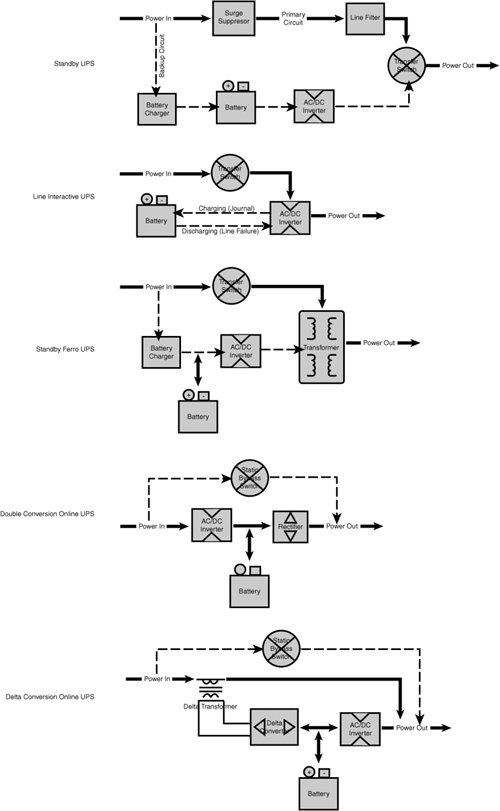
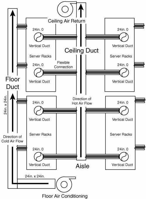
Now that you know what kinds of UPSs are available, you need to specify which kinds of UPSs and how much capacity you need. For standard servers, you can get by with a single backup system, referred to as an N topology, where there are no redundancies. An N topology should be able to supply a full load (100%) to critical systems for the amount of time you deem necessary. To add redundancy you might want to move up to an N+1 topology, where an additional UPS device is added to any number (N) of UPSs. While a server can run at 90% load, a UPS cannot. If a double conversion or delta conversion UPS surges over its stated load, the device shuts down and goes into a utility bypass mode. Power to backed-up systems is lost. UPS devices are very unforgiving in that way. Finally, for mission-critical systems, you might have a 2N topology, where each and every UPS system is backed up by another UPS system. However, for mission-critical systems, what you really want is a backup generator to keep them going. A UPS for a mission-critical system is your very last line of defense and should give you enough time to repair or replace a generator. Considering Raised FlooringThere was a time when old mainframes were put into chilled rooms with raised flooring because these mainframes contained a large number of mechanical devices, vacuum tubes, and other equipment that ran very hot. Raised flooring was just one of the ways of keeping those behemoths cool. While times have changes in many ways, using a raised floor and the correct ventilation are still effective means of greatly increasing airflow in a room, by perhaps 50% or more. Raised floors are usually from 12 inches to 24 inches off the ground. That allows duct work to flow to the air intakes that many cabinets and racks have, which in turn makes for greatly enhanced airflow. A raised floor is generally constructed by placing a metal load-bearing framework or support grid onto the server room floor. The assembly looks a little bit like an erector set. Most raised floors use tiles or panels that are 2 feet by 2 feet, or 4 feet square. The space below the panels is called the plenum, and tiles can be either solid, perforated, or grated. One of the nicest features of raised flooring is the ability to shape your cooling system flow by using the floor panels. Raised flooring requires additional ceiling height in the server room of as much as 2 feet, which can add to building costs. Raised flooring also offers additional benefits such as providing a place to run cabling and to remove power lines from sight. However, many people find that raised flooring results in poor cable management due to difficulty of access, and that can lead to a situation where cables that are not in use are simply left in place. Therefore, some thought should be given to how the raised flooring is used and what kinds of access features it has. While you still find raised flooring in the smaller data centers and in control rooms, there's been a trend in data centers to avoid putting in raised flooring. Larger data centers tend to avoid that additional complexity and instead invest their time and effort in more robust heat dissipation and electrical facilities. When using a raised floor, it is important to remove any under-the-floor obstructions as well as to seal the floor below the subfloor; doing this improves the flow of cool air to the hot-running systems above the floor. Because you are counting on the floor to provide airflow, all open or missing floor tiles should always be replaced, and any cable cutouts should either be sealed or replaced. Cable cutouts are a major source of air leak. You want the cold air to flow up and through your systems, so flooring in aisles should be closed tiles, and that under the equipment should be open. With server racks that are large and heavy, you need to be concerned with the weight-bearing capacity of the raised flooring. The load-bearing capacity of a raised floor today, using cast aluminum tiles, is rated at more than 1,500 pounds, even when you use tiles that are 55% perforated. If you use metal flooring, you should ensure that the floor is nonconductive. Also, you should avoid using as flooring any material that traps dust and dirt or that creates particles. You wouldn't want to use carpet-covered panels, for example, even though carpet would provide the electrical isolation you might want. If you plan on deploying a set of large server racks, you might find that you require a room height of nearly 10 feet in order to accommodate the floor, server, and ceiling fixtures. Another issue associated with raised flooring is that it doesn't permit the use of locked cages in large data centers. Many ISP and collocation facilities rent out capacity in a data center and use cages or wire fencing to separate the different areas of servers in the data center. In such a case, raised flooring doesn't work. Although raised floors continue to be deployed in server rooms, it seems that fewer and fewer data centers are using them as time goes by because they do have a number of drawbacks. Planning for HVAC and AirflowAs server farms stuff more and more blades into bigger and bigger racks, the problem with heat dissipation has raised its ugly head once more, with a vengeance. High-density blade servers can generate 10kW to 20kW per large rack, but the kinds of cooling solutions that use to be delivered through raised floor plenum typically was designed to provide at most 3kW per rack. As warm air rises and cold air falls, putting adequate cooling at the bottom of a room and exhaust at the top of the room should handle the heat load. Cooling equipment, like power equipment, should be redundant. You don't want your servers to burn up because an HVAC unit has failed. Most data centers invest in larger cooling capacity and UPS equipment rather than having redundant cooling. To calculate the amount of air-conditioning required for a server rack, you need to figure that every kW of power used will generate slightly more than 3,400BTU/hr, or 0.28 ton of refrigeration, referred to as a tonref. Most air-conditioners are specified in the United States by the BTU/hour rating. Thus a server rack of 36 1U servers, each consuming about 0.2kW of power, requires the dissipation of 7.2kW, or 24,480BTU, per hour. It probably makes sense to maintain your HVAC equipment on its own power circuit and not on the same circuit as your servers. HVAC equipment tends to be more tolerant of voltage fluctuations than server equipment. If you are trying to determine the amount of refrigeration and the power needed to run that equipment, you might want to go to the American Society of Heating, Refrigerating, and Air-Conditioning Engineers (ASHRAE) website, at www.ashrae.org, where you can find information on how to estimate data center and server room environmental requirements. Most data centers run at temperatures ranging from 67°F to 73°F (19°C to 23°C), and the recommended humidity is between 40% and 55%. A rack that accommodates 36 1U servers is considered to be a medium to larger rack size in a data center today, but server racks that are coming to market will consume as much as 20kW. Typically the average rack-based server system consumes a little less than 3kW. There's no getting around the numbers: To keep the temperature stable, each 1kW of power consumed requires 1kW of cooling to remove excess heat. How you distribute your servers can also affect how well your HVAC system works. If you put all your servers together side-by-side, you can overwhelm your cooling system's ability to cool that area. In general, you should distribute servers throughout your server room. In a fully loaded server room, where you may not have the luxury of ideal spacing, you should distribute all your hottest-running racks as best you can. Even more important from the standpoint of airflow is to design your server rack distribution scheme so that hot and cool aisles alternate with one another. What this means is that because racks tend to exhaust air from the back of the server, a hot aisle is one where the servers on both sides of the aisle have the rear of their racks facing the aisle. A cool aisle would be one where the fronts of both servers face the aisle. Aside from having the benefit of better airflow, this arrangement gives you the benefit of not requiring people to be in hot aisles most of the time. Because servers' controls are typically in the fronts of the units, most of the time personnel work on the servers in the server room will be spent in cool aisles. Figure 17.4 illustrates a hot aisle/cool aisle arrangement where cooling is distributed to improve airflow and heat dissipation. Even with a scheme such as the one shown here, when you have adequate HVAC in place, you still may not have enough airflow to make the system work properly. To improve airflow, you can place air distribution units to move additional air from location to location. These units should be protected from power loss in the same way as your other HVAC components. Figure 17.4. This airflow design uses the cool aisle/hot aisle approach. Note Many server personnel think that having one aisle hot and the next one cool is a design defect. Therefore, they use more cooling vents than they should in hot aisles and more hot returns in cool aisles, thus defeating what is intended to be a design feature. It is important to make clear to personnel in a server room that the hot aisles were designed to be hot and should be left that way. The ultimate solution to these hot-running systems is to implement direct cooling to them. Cool air should flow into the server racks at the bottom and be directed out at the top of the rack. Because unused vertical space in a rack can provide a way for hot air to recycle within a cabinet, it is important to install blanking panels and make sure that your cable management doesn't interfere with cooling. When you design an HVAC system, keep in mind that the further you move away from the air intake into the room, the lower the air pressure. The forced air flowing into a server rack close to your HVAC system is therefore stronger than the air flowing into a server rack a few feet away, which in turn is stronger than the air pressure in a server rack further down the line. You can improve the situation by using one of these solutions:
It's best to measure the airflow directly and, if possible, have some form of active flow control. Keep in mind that airflow changes over the course of a day, as the temperature changes and as a function of other factors as well. Figure 17.5 illustrates APC's (www.apc.com) InfraStruXure design for a 20-server rack system. Notice that cables run along the top of the servers, backs of servers face backs of servers, and a built-in system of air handling vents out the top pipe. APC sells racks and has a rack configuration that lets you specify systems such as this. In addition, you can buy fans to place at the bottom of racks, fans that slide into a rack just as any other component would, fan units that run the whole vertical height of a rack (in the back) with intake at the bottom and exhaust at the top, and completely autonomous rack systems that integrate full cooling, electrics, and other components completely into the rack design. Figure 17.5. APC's InfraStruXure solution with integrated cooling is shown here in a 20-server rack configuration.Image courtesy of APC. You should measure your HVAC system's performance from time to time to determine whether it is keeping up. Among the places you should measure the temperature are at your HVAC system's cooled input, at the exhaust of the return air, at several places in hot and cool aisles, and at various heights. If possible, it is best to set up an automated monitoring system. It's also important to institute a regular maintenance scheme for changing filters, checking coolant, recalibrating thermometers, and doing other servicing. Building in SafetyYou can't always prevent disasters, but you can plan for them. When you plan for a range of disasters that could conceivably occur, there are two basic tasks you need to do. First, you need to train your staff on what to do when a specific situation occurs. Second, you need to have appropriate safety equipment on hand to mitigate the problem. These are some of the problems you might encounter:
It's possible to imagine all sorts of disasters, but the problem encountered most frequently is fire. Fires start due to electrical equipment troubles, mechanical failures, and all sorts of other problems. So it is the one hazard you should especially take special care to protect against. You should consider the following safety features as part of your server room deployment:
Caution In order to use some fire extinguishers safely, you need to think about special considerations and equipment. For example, although halon is not toxic, when it is used, it displaces the air in the area and makes it difficult to breathe. Therefore, you need a breathing system in order to use halon fire extinguishers. Other fire suppressants have the same issue (CO2, for example), but not to the same extent. The FM200 halon system is recommended in a data center.
A server room or data center is not a good place to keep combustible materials. Large piles of paper, chemicals, storage packaging materials, and other combustibles should be removed from the area. Smoking should be forbidden both from a fire prevention standpoint and from a particulate contamination standpoint. Safety also means that all your systems should be inspected and periodically maintained according to manufacturers' specifications. One area where fires often begin is in HVAC systems, when dust has collected in areas where the system is heated, such as reheating coils. Planning for Physical Security and AccessThe best security software available can't defeat an insider who can gain physical access to a system. Even if a person can't log in to the system, physical access makes it possible to damage systems or to remove data in its physical form for later access. You can't eliminate improper use of equipment by authorized personnel, and you also can't eliminate many accidents, but you can lower the risk of non-authorized or inexperienced users getting access to facilities that they are not supposed to have access to. Given that more than 60% of downtime is attributed to operator error, anything you can do to lower the risk is worth considering. The first line of defense in a physical security scheme is to require users to reliably identify themselves. There are a variety of ways to do this, including using fingerprints, hand scans, eye scans, facial scans, and physical keys such as smart cards. These systems identify the user requesting access, but they do not identify why the user is trying to access the room. The second level of physical security is to define the perimeter of the area that needs to be protected. The following areas can be security boundaries:
Because physical security of a server room also includes the facilities necessary to make your systems work, access to UPS and power systems, as well as HVAC systems, may also need to be protected. When designing security systems, many consultants try to establish a set of concentric security perimeters, with increasingly secure methods of validating a person's access as he or she moves to inner perimeters. Thus while a maintenance person might have access to offices and common areas, only personnel with greater clearance, such as vetted maintenance personnel, IT staff, and management, would have access to the data center area. To gain access to the actual server room, the number of personnel would be even more limited, to many fewer people, eliminating most if not all maintenance staff, most of the IT staff, and probably most if not all of the management staff, with the exception of high-level IT managers. In selecting identification and access systems, you should think in terms of functionality. You could broadly categorize devices into the following types:
All the aforementioned devices can authenticate a user but do nothing to protect against a second person getting access by following closely behind an authenticated user, called piggybacking or tailgating. To prevent this type of access, you may need to use entry doors that physically allow only one person to pass through at a time. Another way to monitor this type of entry is through camera surveillance or the use of a guard. |
EAN: 2147483647
Pages: 240