Tape Backup Units
| A tape backup drive is the most simple and efficient device for creating a full backup of a hard disk if the tape is large enough. With a tape backup drive installed in a computer, you insert a tape into the drive, start your backup software, and select the drive and files you want to back up. The backup software copies your selected files onto the tape while you attend to other business. Later, when you need to retrieve some or all of the files from the backup tape, you insert the tape in the drive, start your backup program, and select the files you want to restore. The tape backup drive takes care of the rest of the job. Tape drives come in a variety of industry-standard as well as some proprietary formats. This chapter covers the major industry-standard formats:
Note A servo track is a prewritten track that is used to ensure that data is written in a readable manner. Ultrium and several other types of tape backup technologies use servo tracks. Most current tape drives and all tape libraries support LVD SCSI interfaces, although some also support USB, ATA/IDE, Narrow SCSI, and FireWire interfaces. The following sections provide details. TravanTravan is a family of quarter-inch tape drives and cartridges that 3M (now Imation) developed in 1994. Travan was designed to support backward compatibility with certain QIC and QIC-Wide tape cartridges and to boost capacity and reliability. Note QIC was the Quarter-Inch Cartridge Drive Standards, Inc., trade association, which developed standards for quarter-inch tape drives and media starting in the early 1980s. QIC-Wide was a Sony-developed technology that was based on QIC MC standards but used a wider (8mm) tape. Although the QIC trade association became inactive in 1997, the QIC website is still online, at www.qic.org. The information provided there can be useful if you need to determine drive and media compatibility for QIC tape backups in your archives or need to retrieve files from a .qic backup file. Travan drives, unlike larger tape backups, fit into a 3.5-inch form factor. Travan drives maintain backward compatibility with various QIC standards and provide backup capabilities up to 20GB uncompressed and 40GB at 2:1 compression. Table 9.1 provides a guide to the Travan family tree. Note that the only current versions of Travan are Travan 20 (NS-20, TR-5) and Travan 40 (TR-7).
Nonstandard versions of Travan technology included the 5GB Tecmar/Iomega DittoMax, 5GB Hewlett-Packard/Colorado, 6.6GB AIWA Bolt, 7GB Tecmar/Iomega DittoMax, 10GB Tecmar DittoMax, and 14GB Hewlett-Packard/Colorado. These drives are basically orphans and should be used only to recover archival data stored on media that cannot be read on a standard Travan drive. Note Backward compatibility can vary with drive; consult the manufacturer to verify backward compatibility issues before purchasing any drive. Current Travan Drives and MediaTravan NS drives (Travan NS-8, Travan 20, and Travan 40) use a dual-head design that permits verification during the data writing process instead of requiring the user to rewind the tape and reread it for verification, as with older Travan, QIC, and QIC-Wide drives. Travan NS drives also use hardware-based data compression for faster backups instead of software-based data compression, as with older Travan products. Travan 20 and 40 drives are currently available from Quantum, thanks to Quantum's 2005 acquisition of Certance (formerly Seagate Removable Storage Solutions LLC). Travan 40GB drives are available in internal ATA/IDE and external USB 2.0 form factors. Travan 20 drives are available in internal ATA/IDE and SCSI-2 and external USB 2.0 form factors. Certance/Quantum model numbers include the following:
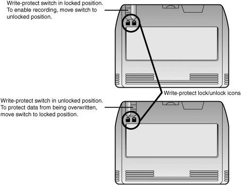
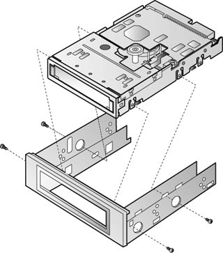
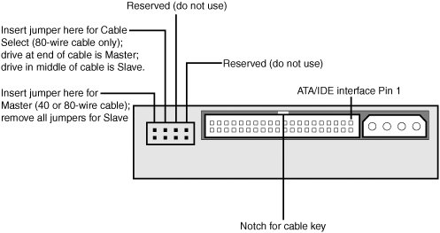
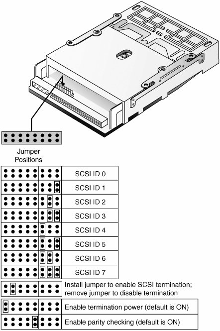
Media is available from Quantum and from many other vendors, including Dell, IBM, Imation, Sony, and Seagate. Figure 9.1 illustrates a typical Travan 20 or Travan 40 data cartridge. Before backing up to this type of media, you need to make sure the cartridge's write-protect switch is open (unlocked) for recording. When you've completed a backup, you should close the write-protect switch to prevent accidental overwriting on a cartridge that contains archival data. Figure 9.1. Setting a Travan 20 or 40 cartridge's write-protect switch. Installing a Travan 20/40 Physical DriveTravan 20 and 40 ATAPI (ATA/IDE) and SCSI-2 drives can be installed in a 3.5-inch or 5.25-inch drive bay. If a 5.25-inch drive bay is used, you use a mounting bracket kit like the one shown in Figure 9.2. The mounting bracket kit provides the large faceplate needed to completely cover the 5.25-inch drive bay opening and extends the sides of the drive so that the drive can be mounted in the larger drive bay. If the case uses drive rails, you attach them to the sides of the mounting bracket kit. Figure 9.2. Installing a Travan 20 or 40 drive into a mounting bracket kit to permit installation in a 5.25-inch drive bay. Travan 20 and 40 USB drives do not require special installation and can be connected to any USB 2.0 port. These drives can be used with USB 1.1 ports, but performance will be severely limited. Configuration for Travan ATAPI DrivesTravan 20 and Travan 40 drives cannot be used on the same ATA/IDE cable as an ATA/IDE hard disk and should always be connected to a separate cable. However, the second cable can also host an ATAPI CD-ROM, DVD-ROM, or other removable-media ATAPI drive. By using a separate cable for the tape backup and hard disk drive, the tape backup can run at maximum speed and will not interfere with the hard disk during backup or restoration operations. Although Travan 40 drives have four sets of jumpers on the rear of the drive (see Figure 9.3), only the rightmost two are used. You remove the jumper block to configure the drive as a slave when the drive is installed on the same cable as another ATAPI drive. You insert the jumper block into the rightmost set of jumpers to configure the drive as master. If an 80-wire Ultra ATA cable is used, you can insert the jumper into the Cable Select jumper one position to the left from the Master jumper. Figure 9.3. Jumper selections for a Travan 40 ATAPI drive. Travan 20 drives use the traditional three-position jumper (Master, Slave, Cable Select) used by most other ATA/IDE and ATAPI drives. The jumpers are mounted on the bottom of the drive rather than at the rear. Configuring Travan 20 SCSI-2 DrivesTravan 20 SCSI-2 drives are designed to work on Narrow SCSI (50-pin) interfaces rather than the 68-pin LVD SCSI interfaces used by most SCSI-interface tape backups for servers. The drive uses a standard 50-pin SCSI-2 ribbon cable. The configuration jumper pins are located on the bottom of the drive. They permit the drive to be configured for any SCSI ID between 0 and 7 and are also used to enable or disable termination, provide termination power, and enable parity checking (see Figure 9.4). Figure 9.4. SCSI configuration for a Travan 20 SCSI-2 tape backup drive. Note that the drive is upside-down in this view. Termination power and parity checking are enabled by default. If another device on the SCSI daisy chain, such as a hard disk, is already configured to provide termination power, you need to disable the tape backup's termination power setting. If double bus termination power is present, backup problems can result. Parity checking should always be left enabled to ensure reliable backups; you should disable it only for diagnostic purposes. If the drive is located at the end of the SCSI daisy-chain (that is, at the end of the cable), you insert the termination jumper. If the drive is located elsewhere in the daisy-chain, you remove the termination jumper. Travan Software Drivers and Utility ProgramsThe Travan 20 and Travan 40 drives currently sold at retail include Yosemite TapeWare XE Server/Workstation backup software. This backup program supports the following server operating systems for ATAPI drives: Windows NT 4.0, Windows 2000 Server, Windows Server 2003, and Linux for ATAPI drives; and Windows 2000 Server and Windows Server 2003 for USB drives. For third-party backup software support, you should go to the software vendor's website or use the Quantum compatibility guide that is available at www.quantum.com/ServiceandSupport/CompatibilityGuides/Index.aspx. If you plan to use Travan 40 ATAPI drives with the built-in backup programs in Windows NT 4 or in Windows 2000 Server/Windows Server 2003, you can download drivers from www.quantum.com/ServiceandSupport/SoftwareandDocumentationDownloads/Travan40ATAPI/Index.aspx. These versions of Windows have native support for Travan 20. TapeRX diagnostics for Travan 20 and Travan 40 drives are available for Windows, Linux, NetWare, and Solaris, from www.quantum.com/ServiceandSupport/SoftwareandDocumentationDownloads/Travan40USB2.0/Index.aspx. DDS-3, DDS-4, and DAT72 Tape DrivesOf the many high-performance] tape drives on the market, a great choice for use with entry-level to midrange servers is the DAT/DDS tape drive family because of its combination of performance, capacity, reliability, and reasonable price. Current members of the DDS family include the following:
Note Some DDS-4 drives are also read compatible with DDS-2 media, which means they can be used in place of older drives for retrieving existing backups. Some DDS-4 drives are also read/write compatible with DDS-2 media, which means they can reuse DDS-2 media. It's important to check media compatibility with the drive manufacturer for details. DDS and DAT 72 drives use helical scan recording. The read/write heads used in helical scan recording are mounted on a drum and write data at a slight angle to the tape, using a mechanism highly reminiscent of that in a VCR. The entire surface of the tape is used to store data, enabling more data to be placed in a given length of tape than with the linear recording techniques that the QIC and Travan family of drives use. Table 9.2 lists current DDS-3, DDS-4, and DAT 72 drives, interfaces, and form factors, by manufacturer. Vendors such as IBM and Dell are not listed; they do not manufacture DDS and DAT drives but instead re-label drives from other vendors. Sony, the originator of the DDS standard, no longer makes DDS drives.
In 2006 and 2007, the next generation of DAT/DDS, DAT 160 (80GB native/160GB 2:1 compression) should be released. For a complete road map of DAT/DDS technology, visit the DAT Manufacturers Group website, at www.datmgm.com. Quantum and Hewlett-Packard-Specific DDS/DAT 72 FeaturesQuantum's DDS-3, DDS-4, and DAT 72 drives feature a combination of technologies called TapeShield that are designed to protect drives and data:
These improvements enable DAT 72 drives to run 10 times longer in dusty conditions than similar drives that don't have these features. DDS-3, DDS-4, and DAT 72 drives from Quantum also feature SmartShield, which uses multiple reads to improve data recovery when reading from out-of-spec or weak recorded tapes. Hewlett-Packard's DAT 72 drives include self-cleaning features and One Button Disaster Recovery, an easy-to-use disaster-recovery feature designed to restore a system to its most recent backed-up condition with the press of a button. This feature is supported on several Hewlett-Packard ProLiant servers. See http://h18006.www1.hp.com/products/storageworks/drs/index.html for compatibility information and technical notes. DDS and DAT 72 MediaDDS and DAT 72 media is labeled with one of the logos shown in Figure 9.5. Current drive manufacturers recommend (of course!) their own brand of media. If you prefer a third-party brand, you need to make sure it supports the appropriate DDS or DAT level. Figure 9.5. DDS and DAT 72 logos. When used on media, the DDS logo (top) is accompanied by a number that lists the DDS version (middle). Even though DAT/DDS drives are more expensive than Travan drives with similar capacities, the drive's design is such that the cost of media is lower. For example, a DDS-4 data cartridge is about US$10 in single quantities, compared to about US$50 for a typical Travan 40 data cartridge in single quantifies. A DAT 72 cartridge is about US$23 in single quantities. Over time, a DDS-4 or DAT 72 drive is far less expensive to operate than a Travan 40 drive because of the sharply lower media cost. Configuring and Installing a Quantum DDS/DAT 72 Tape BackupQuantum DDS-3, DDS-4, and DAT 72 SCSI drives are designed to work with many different server operating systems, not just Windows. Consequently, installation and configuration of these drives is much more complex than with a Travan drive. Before installing any drive, you need to install the software drivers provided with the drive. If additional software is needed, you should download it from the support page for the drive. You can download drivers for Windows, Linux, and other operating systems; TapeRX diagnostics; and firmware updates. To download these files, you select the drive type from the Quantum Software and Documentation Downloads page, at www.quantum.com/ServiceandSupport/SoftwareandDocumentationDownloads/index.aspx. A Quantum DDS or DAT 72 internal SCSI drive has several sets of jumpers or DIP switches:
You configure external drives in the following ways:
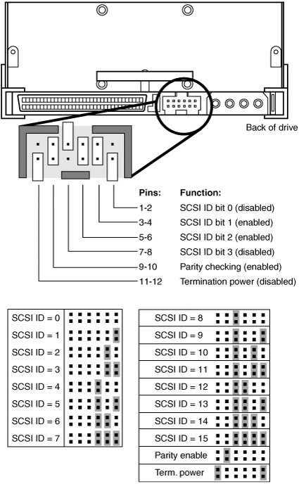
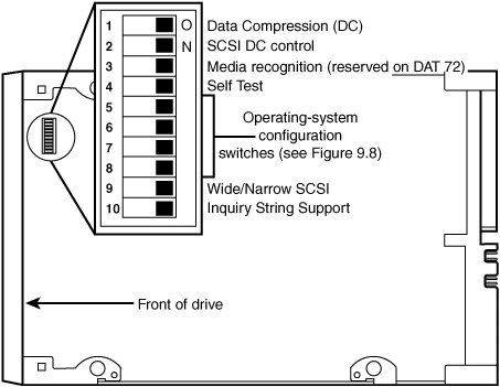
Figures 9.6 and 9.7 show examples of these jumpers and switches. Figure 9.6. The default SCSI Device ID, parity checking, and termination power jumper settings for Quantum internal DDS-4 and DAT 72 drives. Figure 9.7. Default settings for advanced tape drive configuration DIP switches on Quantum internal and external DDS-4 and DAT 72 drives. Note Depending on the drive, documentation for a Quantum DDS or DAT 72 drive might be labeled Seagate, Certance, or Quantum. Seagate was the original manufacturer of most of these drives, before it spun off its tape drive division as Certance. Quantum then purchased Certance in 2005. Generally, DIP switches 1 through 4 and 9 should be left in their default ON position. However, depending on the server operating system you use, you might need to adjust the position of DIP switches 5 through 8 and 10. The default ON setting shown in Figure 9.7 configures these drives to support Windows NT 4.0, Windows 2000 Server, Windows 2003 Server, Windows 98, Windows Me, and Windows XP. Table 9.3 lists the appropriate configurations for other operating systems.
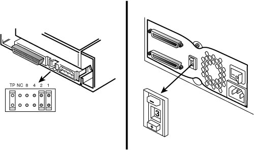
Internal DDS-3 drives use a 10-position DIP switch on the underside of the drive for SCSI ID and other configuration settings. The SCSI ID can also be configured with DIP switches on the rear of the drive. For details, see http://downloads.quantum.com/Certance/manuals/userguides/user_guide_stdx24000n_en.pdf. You use external terminators with Quantum internal SCSI tape backups if the drive is at the end of the SCSI daisy-chain. Quantum internal drives fit into half-height 5.25-inch drive bays. All external SCSI tape backups from any vendor require termination if the drive is at the end of the SCSI daisy-chain. Configuring and Installing a Hewlett-Packard DDS or DAT 72 Tape Backup DriveHewlett-Packard provides a CD containing its StorageWorks Library and Tape Tools with its drives. If the CD contains drivers for your operating system, you should install the appropriate drivers. If a driver for your operating system is not supplied with the drive, you can download updates from the Hewlett-Packard website. To determine software compatibility with a particular Hewlett-Packard tape backup drive, you can go to www.hp.com/go/connect, click Tape Backup, and then click Software Compatibility. Next, you click the entry for each combination of drive and operating system for compatibility details and links to driver updates. Unlike Quantum's SCSI DDS and DAT 72 drives, which depend on a combination of software drivers and DIP switches to configure a drive for a particular operating system, Hewlett-Packard tape drives use software drivers. To configure the SCSI Device ID on an internal drive, you use the jumper blocks on the rear of the drive. Hewlett-Packard SCSI tape drives are generally configured using Device ID 3; if you need to change the default ID, refer to Table 7.6 in Chapter 7, "The SCSI Bus." The jumpers used to configure the device ID are numbered 1 through 4, from right to left. Other jumpers should not be moved from their default locations. You configure external drives using push buttons to select SCSI IDs. Hewlett-Packard DDS-3 drives support SCSI IDs 0 through 7; Hewlett-Packard DDS-4 and DAT 72 drives use a Wide SCSI interface and support SCSI IDs 0 through 15. Figure 9.8 illustrates the location of the SCSI ID jumper blocks and external switch on a Hewlett-Packard DDS-3, DDS-4, or DAT 72 drive. Figure 9.8. Configuring the SCSI ID on an Hewlett-Packard internal (left) and external (right) tape drive. You use external terminators with Hewlett-Packard SCSI tape backups if the drive is at the end of the SCSI daisy-chain. Hewlett-Packard internal drives fit into half-height 5.25-inch drive bays. To install a Hewlett-Packard USB 2.0 drive, you connect the drive to a USB 2.0 port built into the server or an add-on card. For best performance, you should not connect the drive to a USB 2.0 hub. DLT and SDLTDigital linear tape (DLT) technology was originally developed by Digital Equipment Corporation (DEC) in 1991. DEC sold its DLT business to Quantum in 1994, and since then, DLT and its higher-capacity sibling, Super DLT (SDLT), have become some of the leading high-end tape backup technologies. Both DLT and SDLT drives are manufactured and sold by many vendors, including ADIC, Hewlett-Packard, IBM, Overland Storage, Quantum, and Tandberg Data. DLT segments the tape into parallel horizontal tracks and records data by streaming the tape across a single stationary head at 100 inches to 150 inches per second during read/write operations. This is in dramatic contrast to traditional helical-scan technology used by DDS and DAT 72 drives, in which the data is recorded in diagonal stripes, with a rotating drumhead, while a much slower tape motor draws the media past the recording head. The result is a very durable drive and a robust medium. DLT drive heads have a minimum life expectancy of 15,000 hours under worst-case temperature and humidity conditions. DLTtape III has a life expectancy of 500,000 passes, and DLTtape IIIXT and DLTtape IV double the life expectancy to 1 million passes. SDLT uses several technologies to increase capacity and reliability over those of the already-impressive DLT standards. These include laser-guided magnetic recording (LGMR), a pivoting optical servo on the backside of the media, thin-film magneto-resistive cluster heads for tape reading and writing, high-efficiency PRML channels for greater recording density, improved media coating, and a positive engagement tape-leading buckling mechanism. SDLT drives can read SDLT and DLT media up to six generations back. This enables you to replace older, smaller drives with newer, larger drives without losing access to older backups. Note SDLT and DLT media use different head cleaning cartridges because of the differences in recording head and media technologies between DLT and SDLT. Current DLT and SDLT Drives and MediaAlthough DLT drives have previously been available in capacities as low as 10GB native/20GB at 2:1 compression (DLT-2000), the smallest-capacity DLT drive currently on the market is the DLT VS80, which has a capacity of 40GB/80GB (2:1 compression). Table 9.4 lists the specifications for current DLT and SDLT drives. All current DLT and SDLT drives are designed to connect to Wide SCSI (68-pin) interfaces.
DLT media is available in three families: DLTtape III, DLTtape IIIXT, and DLTtape IV. Current installations of DLT drives are most likely to support DLTtape IV. This media can also be read by SDLT drives. SDLT media is available in two families: Super DLTtape I (SDLTtape I) and Super DLTtape II (SDLTtape II). Table 9.5 lists the specifications for DLT and SDLT media.
Configuring and Installing DLT and SDLT DrivesCompared to DDS and DAT72 /tape drives, the configuration of current DLT and SDLT drives is relatively simple. The software drivers used by DLT and SDLT drives are used to optimize these drives' operations with different operating systems rather than the configuration jumpers used by DDS and DAT72 tape drives. The only hardware setting used by current DLT and SDLT tape drives is the SCSI device ID. For internal drives, you use jumper blocks on the rear of the drive to configure the SCSI device ID. For external drives, you use push buttons to set the device ID. Figure 9.9 illustrates typical DLT drives, the Quantum DLT VS80 in its external and internal versions, and the SCSI device ID settings used on these drives. For other drives, see the documentation. Figure 9.9. Rear views of the Quantum DLT VS80 external (top) and internal (bottom) tape drives.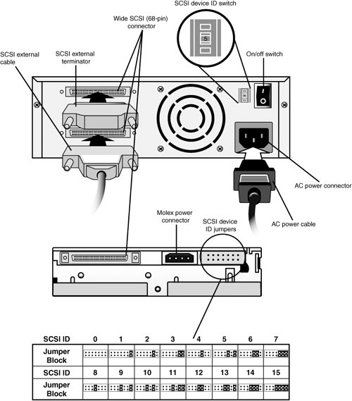 As with any SCSI drive, if a tape drive is the last drive in the daisy-chain, it must be terminated. With external drives, you connect an external terminator to the second connector on the drive (refer to Figure 9.9). To terminate an internal drive, you connect the terminator/to the data cable connector at the next position past the drive. LTO UltriumLTO Ultrium is the highest-performing and highest-capacity open standard tape backup system currently available for servers. Ultrium was developed by the Linear Tape-Open (LTO) Technology organization, co-founded by Hewlett-Packard, Seagate, and IBM in 1997. Originally, LTO developed two standards: Ultrium (optimized for high capacity) and Accelis (optimized for high speed). Accelis was never adopted, in large measure because Ultrium provided comparable speeds at higher capacities. Thus, Ultrium and LTO are sometimes used interchangeably. The first Ultrium drives (LTO-1) were released in 2000. Currently, LTO-1, LTO-2, and LTO-3 drives are available from many vendors, including Hewlett-Packard, IBM, Quantum, and Tandberg Data. Note To learn more about Ultrium and LTO, visit the LTO Technology organization website, at www.lto.org LTO Ultrium technology divides a 384-track half-inch tape into four data bands, separated by servo bands. Each read/write head contains eight elements. Two servo bands are used simultaneously to provide accurate head positioning and to overcome any flaws in the media. Tape is written bidirectionally at very high speeds. Each data band is written in the opposite direction from the previous band to help avoid cross-talk between data bands. Each Ultrium cartridge contains a NVRAM chip that provides calibration and other information. The drive reads this information and uses it to help operate the cartridge in an optimal manner. This information can also be read by an RF receiver before the cartridge is inserted into a tape drive. As with other current tape backup technologies, Ultrium uses the read-while-write method of data verification. If data cannot be verified, it is rewritten on another portion of the tape during backup. LTO Ultrium Drives and MediaUltrium products are currently available in three generations: LTO-1, LTO-2, and LTO-3. Each generation doubles the native and 2:1 compressed capacity compared to the previous generation, and each generation also significantly increases the compressed transfer rate. Table 9.6 lists current Ultrium drives from major vendors.
Note Full-height LTO drives offer faster performance than half-height versions. Table 9.7 lists the specifications for each LTO Ultrium standard. As this table indicates, LTO-3 drives are read/write compatible with LTO-2 media and can read LTO-1 media. LTO-2 drives are read/write compatible with LTO-1 media. As LTO continues to be developed, forthcoming drives are expected to continue to feature read/write compatibility with the previous generation and read compatibility two generations back. Backward compatibility makes it easier to move up to higher-capacity drives without the necessity to convert existing backup data to a new drive format.
Configuring and Installing LTO Ultrium DrivesAs with DLT and SDLT drives, configuring LTO Ultrium SCSI drives is relatively simple. With external drives, you use push buttons to set the device ID. With internal drives, you use jumper blocks on the rear of the drive to configure the SCSI device ID (see Figure 9.9 for examples of both types of drives). See the drive's documentation for specific jumper configurations. If a drive is the last drive in the daisy-chain, it must be terminated. With external drives, you connect an external terminator to the second connector on the drive. To terminate an internal drive, you connect the terminator to the data cable connector at the next position past the drive. Before connecting a drive to your system, you should install the drivers included with the drive. You can visit the vendor's support site to download updated drivers. Tape AutoloadersIf tape capacity had kept pace with hard disk capacity, it would be easy to make backups: You could just install a single blank tape in the tape backup and start the process. Then you could label it when you're finished and put it aside for storage. However, in many cases today, a single backup requires multiple tapes:
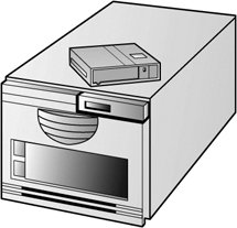
To avoid the need to manually load tapes for a multiple-tape backup, you can consider a tape autoloader. An autoloader is an external device that contains a single tape backup drive and holds anywhere from 8 to 16 tape cartridges. When the first cartridge is full, the autoloader removes it and inserts another. The process is repeated until the backup task is finished. Tape autoloaders are available in DDS/DAT, DLT, SDLT, and LTO-Ultrium formats. Most vendors that sell individual tape drives also sell autoloaders, and autoloaders are also manufactured by companies that incorporate third-party tape drives. Figure 9.10 illustrates a typical autoloader for DLT cartridges. Figure 9.10. A typical 8-slot autoloader for DLT cartridges. Autoloader Drives and MediaTable 9.8 lists the specifications for the most common autoloaders based on the drives covered earlier in this chapter.
The media used by an autoloader is the same as that used by a single tape drive, using the same technology. Autoloaders have trays or cassettes that hold the media when not in use. To simplify calculation of native and compressed capacities, you should use the same size and type of media for each cartridge, even if the drive can read and write to more than one size of media. Installing AutoloadersMany autoloaders are designed and configured for rack installation. A 2U-sized rack is normally used. A team of two people should work together to install the unit into a rack: one to hold the unit, and the other to fasten the unit to a rack. Some autoloaders are designed to work in a full-height 5.25-inch drive bay, and others can be placed on a desktop. Most autoloaders use Ultra160 SCSI interfaces, but some are available in 2Gbps Fibre Channel interfaces as well. For best performance, autoloaders as well as single tape backup drives should be connected to a separate SCSI channel from SCSI drives or RAID arrays. If the vendor recommends it, you should connect the autoloader to a slot-based SCSI host adapter rather than to a SCSI RAID or integrated SCSI host adapter. If necessary, you should install the recommended SCSI host adapter into the server before continuing. You need to be sure to terminate the autoloader if it is the last (or only) device on the SCSI bus. Generally, this requires that you attach the appropriate type of terminator to the unused SCSI connector on the rear of the autoloader. When you fill the autoloader's magazine with data cartridges, you need to make sure each cartridge is not write-protected. Some autoloaders require you to insert the cartridges one at a time. Others use multicartridge inserts. If the unit is a dual-capacity 8/16 cartridge unit, you must use a magazine blank and a single eight-cartridge magazine or else two magazines of eight cartridges each. The front panel is used to perform most initial setup and management tasks. Depending on the autoloader, typical options might include the following:
Even if you plan to use remote network management for an autoloader, you must first configure devices that support remote management with the appropriate IP address and other network configuration settings. Some autoloaders, particularly those made for DAT 72 and DDS-4 media, might require you to configure the drive with DIP switches and a back panel option switch if you plan to use a Linux or other non-Windows operating system with the autoloader. Typically, the default setting supports Windows operating systems. If the autoloader includes a web-based management interface, you need to connect an RJ-45 cable from your network to the RJ-45 (Ethernet) port on the rear of the autoloader. After you use the front panel to configure the autoloader, you can log in to the autoloader's IP address and perform most of the management tasks you can also perform through the device's front panel controls. Some of the tasks you will find particularly useful to perform remotely include cartridge inventory, cleaning the drive (if a cleaning cartridge is installed), moving a cartridge, viewing drive usage statistics, running diagnostic tests, and configuring a single IP address or range of IP addresses authorized to manage the drive. Note that autoloaders can also be configured to work in an Auto Clean mode if a cleaning cartridge is installed. Autoloader TroubleshootingAutoloaders are a good bit more complex than single tape backup units. To troubleshoot a unit, you use the front-panel display or remote management. If the device stores log files, you should examine them, which typically requires you to log in to the unit remotely. If the vendor provides diagnostic software, you should run it to determine problems. Note that the diagnostic software provided with the unit might not be compatible with some operating systems. You can visit the vendor's website for the latest versions. You need to verify that the autoloader works with your tape backup application. For some backup software, whether built in to the operating system or provided by a third party, you might need to install patches or updates to enable it to work with an autoloader. You can check the autoloader vendor's website for compatibility information and links to update files. You need to be sure to check SCSI-specific settings, such as device IDs (each device on a particular SCSI bus must have a unique SCSI ID), cabling, and termination. You also need to check the signal lights on the front of the unit, which are used to report various problems. The patterns of flashing lights or, on some units, the color of the LED, are used to indicate various problems. You should see your unit's documentation for details. If the drive is not using the latest firmware and you are having problems, you should update the firmware. Tape Libraries and Enterprise UnitsAs the previous section discusses, tape autoloaders enable you to automate tape backup and archiving to handle the backup requirements of large hard disks. However, if you are responsible for an enterprise-level server, an autoloader might not provide enough capacity or sufficient management options to be suitable. In such cases, you should consider a tape library. A tape library resembles an autoloader, but with the following differences:
Tape libraries are normally based on the largest and fastest tape backups available in a particular technology. These are the most common choices:
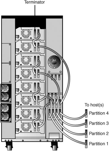
Some tape libraries support only one type of drive, but others support mixing LTO Ultrium and SDLT drives in the same unit. This is useful because LTO-3 Ultrium and SDLT 600 media are now available in a special write-once, read-many (WORM) format. Thus, you could partition a tape library could to write data for permanent archiving to the drive using WORM tape media and data for backup and later reuse and replacement to the library's other drive, using standard rewritable tape. Installing Tape LibrariesTape libraries usually require some assembly. You might need to install the entry/exit port (used to move cartridges), support legs, and a conversion kit to convert a tabletop unit into a rack-mounted unit. Some libraries also require you to install the tape drives and to add additional power supplies for redundancy or to provide necessary power for a larger number of tape drives. Tape libraries, unlike tape autoloaders, usually include one or more onboard SCSI host adapters in a mini-PCI form factor. The SCSI host adapter is used to run the library's robot tape loading/unloading/movement mechanism. If the tape library will be partitioned into two or more logical libraries, additional SCSI host adapters are needed in the library (see Figure 9.11). Figure 9.11. A tape library configured as four logical libraries. Depending on the size of the tape library, one host adapter might be used to run one or more drives. Each tape drive in a tape library, as well as the library itself, requires a SCSI device ID. For example, a tape library with two tape drives requires three unique SCSI device IDs. Special short patch cables are used for daisy-chaining SCSI drives to each other. You use the front panel to configure the SCSI device IDs, other SCSI settings (mode, bus parity, and so forth), Fibre Channel options, library partitioning, reserved slot(s) for cleaning cartridges, TCP/IP network settings, front panel and media security locks, and magazine access (for loading or removing cartridges). You also use the front panel for viewing and changing system settings such as cartridge access mode, automatic cleaning, cartridge mapping (displays cartridge names), emulation (necessary to enable some backup programs to operate with certain libraries), and library maintenance (rebooting, updating firmware, and so forth). If a tape library is connected to a Fibre Channel switch, one cable from the switch is connected to the library, and a separate cable from the switch is connected to each drive built in to the tape library. To permit remote management, you connect an RJ-45 Ethernet port in the tape library to an RJ-45 cable from your network. To manage the tape library via a web browser, you enter the IP address assigned to the unit and provide a password to log in to the unit. You can normally perform most configuration options through the web browser. To create a library partition, you must specify which SCSI or Fibre Channel host adapter card will control access and specify which tape cartridge slots and drives are assigned to that partition. A tape library requires at least one and sometimes more AC power cords. You need to be sure to provide an AC outlet with adequate power to run the tape library. Tape Library TroubleshootingLearning to troubleshoot a tape library requires that you familiarize yourself with the methods your library server uses for reporting problems. The front-panel LCD display is often used to display problem messages and error codes, for example. If you use remote access, you should check the documentation to determine whether some problems are only reported through the front-panel LCD display. Before you can control the robot remotely, you might need to configure it for remote access. Cartridges are identified by unique bar codes. If the system is unable to locate a particular cartridge, you should check the bar code labels on each cartridge. Any labels that are worn or dirty should be replaced. If the labels are clean, you need to make sure the laser and lens used to read the bar code is not dirty or blocked by debris. You can use the bar code statistics readout to determine failure rates. You can use other reports to find additional problems. On the first sign of a problem, you should try resetting the library. If problems recur, you should contact the company for help. | |||||||||||||||||||||||||||||||||||||||||||||||||||||||||||||||||||||||||||||||||||||||||||||||||||||||||||||||||||||||||||||||||||||||||||||||||||||||||||||||||||||||||||||||||||||||||||||||||||||||||||||||||||||||||||||||||||||||||||||||||||||||||||||||||||||||||||||||||||||||||||||||||||||||||||||||||||||||||||||||||||||||||||||||||||||||||||||||||||||||||||||||||||||||||||||||||||||||||||||||||||||||||||||||||||||||||||||||||||||||||||||||||||||||
EAN: 2147483647
Pages: 240