Video Display Interfaces
| A video interface provides the connection between your system and the display, transmitting the signals that appear as images on the display. Throughout the history of the PC, there has been a succession of standards for video interfaces and displays representing a steady increase in screen resolution and color depth. Early laptop computers used the 4-color color graphics adapter (CGA) and 16-color enhanced graphics adapter (EGA) displays that used digital technology. However, after IBM released its analog video graphics array (VGA) display standard in 1987, laptop builders switched to VGA, and portable displays ever since have been based on VGA, just as desktop displays continue to be based on VGA. Modern laptop video graphics processors and displays support higher resolutions and color depths, and they have other additional capabilities (such as 3D functions) not found in the original VGA specification. However, because of careful design ensuring backward compatibility, most of the latest high-resolution video interfaces and displays can also run most older color graphics software written for CGA, EGA, and most of the other obsolete graphics standards. This enables you to use older software on your current system, even though the video interface and display standards have changed dramatically. Video Graphics Array (VGA)IBM introduced the video graphics array (VGA) interface and display standard on April 2, 1987, along with a family of systems it called PS/2. The first laptop to use VGA was Compaq's SLT/286, which was introduced in 1988. VGA went on to become the most popular video interface in history, and it's still the basis of most modern PC video adapters and displays on both laptop and desktop computers. Unlike earlier digital video standards, VGA is an analog system. When it came out in 1987, it began a shift from digital to analog that has lasted since then. Only recently has there been a shift back to digital, which will probably continue over the next few years. Why go from digital to analog and then back to digital? The simple answer is that analog was the least expensive way at the time to design a system that supported a reasonable resolution with a reasonable number of colors. Now that technology has advanced and LCD displays are fast replacing CRTs, going back to an all-digital format makes sense. The PC video standards that preceded VGA, including the original MDA, CGA, and EGA standards, were digital. They generated different colors by sending digital color signals down three wires, which allowed for the display of up to 8 colors (23). Another signal doubled the number of color combinations from 8 to 16 by allowing each color to display at two intensity levels. This type of digital display was easy to manufacture and offered simplicity, with consistent color combinations from system to system. The main drawback of the original digital display standards, such as CGA and EGA, was the limited number of possible colors. With VGA, IBM went to an analog design. Analog uses a separate signal for each CRT color gun, but each signal can be sent at varying levels of intensity64 levels, in the case of the VGA. This provides 262,144 possible colors (643), of which 256 could be simultaneously displayed in the original design. For realistic computer graphics, color depth is often more important than high resolution because the human eye perceives a picture that has more colors as being more realistic. IBM moved to analog graphics to enhance the color capabilities of its systems. VGA was designed to be addressed through the VGA BIOS interface, a software interface that forced programs to talk to the driver rather than directly to the hardware. This allowed programs to call a consistent set of commands and functions that would work on different hardware, as long as a compatible VGA BIOS interface was present. The original VGA cards had the BIOS on the video card directly, in the form of a ROM chip containing from 16KB to 32KB worth of code. Modern video cards and laptop graphics processors still have this 32KB onboard BIOS (often incorporated directly into the processor itself), although it supports only the same functionality of the original VGA standard. To use higher functionality, additional drivers are loaded into RAM during the boot process, and the ROM BIOS on the card is largely ignored after that. Typically, the only time the ROM-based drivers are used is during boot and when you run Windows in Safe Mode. An original VGA card displays up to 256 colors onscreen, from a palette of 262,144 (256KB) colors; when used in the 640x480 graphics or 720x400 text mode, 16 colors at a time can be displayed. VGA displays originally came not only in color but also in monochrome VGA models, which use color summing. With color summing, 64 gray shades are displayed instead of colors. The summing routine is initiated if the BIOS detects a monochrome display when the system boots. This routine uses an algorithm that takes the desired color and rewrites the formula to involve all three color guns, producing varying intensities of gray, even though the application is attempting to display color. Monochrome displays are obsolete today. Even the least-expensive laptop displays today can work with modes well beyond the VGA standard. VGA, at its 16-color, 640x480 graphics resolution, has come to be the baseline for PC graphical display configurations. VGA is accepted as the least common denominator for all Windows systems and must be supported by the video adapters in all systems running Windows. The installation programs of all Windows versions use these VGA settings as their default video configuration. In addition to VGA, virtually all adapters support a range of higher screen resolutions and color depths, depending on the capabilities of the hardware. If Windows must be started in Safe Mode because of a startup problem, the system defaults to VGA in the 640x480, 16-color mode. Windows 2000 and Windows XP also offer a VGA Mode startup that uses this mode (Windows XP uses 800x600 resolution) but doesn't slow down the rest of the computer the way Safe Mode (which replaces 32-bit drivers with BIOS services) does. IBM introduced higher-resolution versions of VGA called XGA and XGA-2 in the early 1990s, but most of the development of VGA-related standards since then has come from the third-party video card industry, industry trade groups, and standardization committees. Here are the most important of these standards:
The efforts of these groups are the primary influence on video display standards for desktop and laptop PCs and other types of computers. Industry Standard SVGAAfter IBM introduced the VGA standard in April 1987, it seemed to take forever before anything newer and better came out. By 1989, competing system, video card, and display manufacturers had wanted to introduce something better than VGA, but they also wanted to cooperate in order to make the new interface an industry standard as well as make it compatible with existing software and hardware designed for VGA. In February 1989, an international nonprofit group called Video Electronics Standards Association (VESA) was formed to create industrywide interface standards for the PC and other computing environments. VESA was designed to create and promote open standards for the display and display interface industry, which would ensure interoperability and yet also allow for innovation. VESA is led by a board of directors that represents a voting membership of more than 100 corporate members worldwide. The members are PC hardware, software, display, and component manufacturers, as well as cable and telephone companies, service providers, and more. VESA essentially took the role of defining PC video interface standards away from IBM, giving it instead to the VESA members. In August 1989, VESA introduced its first standard, an 800x600 16-color BIOS interface standard called Super VGA (SVGA) mode 6Ah, which allowed companies to independently develop video hardware having a common software interface. This allowed for higher resolution functionality while maintaining interchangeability and backward compatibility with existing VGA. Since then, VESA has extended the SVGA standard to include many other modes and resolutions, and it developed or contributed to many successive standards in PC video. Note that although SVGA technically defines a set of VESA standards that includes modes from 800x600 and beyond, typically we use the term SVGA to describe only the 800x600 mode. Other higher-resolution modes have been given different names (XGA, SXGA, and so on), even though they are technically part of the VESA SVGA specifications. XGA and BeyondNot one to give up without a struggle, for a while IBM continued to develop and release new video standards, despite VESA doing the same. On October 30, 1990, IBM introduced the extended graphics array (XGA). XGA was an evolution of VGA and provided enhanced resolution, color content, and hardware functionality. XGA was also optimized for Windows and other graphical user interfaces. The most exciting feature XGA added over VGA was support for two new graphics modes:
Notably missing from IBM's original XGA interface was the VESA-defined 800x600 16-color mode, which had debuted just over a year earlier. That was important because not many monitors at the time could handle 1024x768, but many could handle 800x600. With IBM's card you had to jump from 640x480 directly to 1024x768, which required a very expensive monitor back then. That oversight was finally corrected when IBM released XGA-2 on September 21, 1992. XGA-2 added more performance and additional color depth, as well as support for the intermediate 800x600 VESA modes:
Since then, VESA and other industry groups have defined all the newer video interface and display standards. IBM became a member of VESA and many of the other groups as well. Although IBM introduced these higher resolutions and color depths in 1991 and 1992, most laptop computers didn't support these standards until the mid-1990s. VESA BIOS Extension (VBE)In October 1991, VESA recognized that programming applications to support the many SVGA cards on the market was difficult, and it proposed a standard for a uniform programmer's interface for SVGA cards: the VESA BIOS Extension (VBE). VBE support might be provided through a memory-resident driver (used by older cards) or through additional code added to the VGA BIOS chip itself (the more common solution). The benefit of the VESA BIOS extension is that a programmer needs to worry about only one routine or driver to support SVGA modes. Various cards from various manufacturers are accessible through the common VESA interface. Today, VBE support is a concern primarily for real-mode DOS applications, usually older games, and for non-Microsoft operating systems that need to access higher resolutions and color depths. VBE supports resolutions up to 1280x1024 and color depths up to 24 bits (16.8 million colors), depending on the mode selected and the memory on the video card. VESA compliance is of virtually no consequence to Windows versions 95 and up. These operating systems use custom video drivers for their graphics cards. Analog VGA ConnectionsVirtually all analog video interfaces since VGA have used the VGA connector and pinout definition. This is why you can plug a brand-new high-resolution analog CRT or flat-panel display into the oldest VGA cards or laptops with an external VGA port, or the oldest displays into the newest cards, and they will all work at the lowest common denominator of resolution, color depth, and performance. The standard 15-pin female VGA connector (on the video card or system) is shown in Figure 11.4; the pinouts are shown in Table 11.3. Figure 11.4. The standard 15-pin analog VGA connector.
The mating VGA cable connector that plugs into this connector normally has pin 9 missing. This was designed such that the mating hole in the connector on the video card could be plugged, but it is usually open (and merely unused) instead. The connector is keyed by virtue of the D-shape shell and pin alignment, so it is difficult to plug in backward even without the key pin. Pin 5 is used only for testing purposes, and pin 15 is rarely used; they are often pinless as well. To identify the type of monitor connected to the system, some manufacturers use the presence or absence of the monitor ID pins in various combinations. Almost all laptops built since the introduction of VGA into laptop design feature the 15-pin connector for external VGA monitors described here. Although laptops have built-in displays, there are several reasons to support external displays:
S-Video/TV-Out ConnectionsS-Video (Separate Video) is an analog industry standard video-transmission scheme that uses a standardized 4-pin mini-DIN (Deutsches Institut für Normung e.V., or German Institute for Standardization) connector to send television-type video information on separate luminance (or brightness, designated as Y) and chrominance (or color, designated as C) pairs. S-Video is sometimes called Y/C video, in reference to the names of the separate luminance and chrominance signals. S-Video was designed to be superior to a composite video signal, which has the Y and C information combined. Composite video requires that the signals be separated by a comb filter inside the receiving device, which can reduce the sharpness of the image. By separating the Y/C signals, S-Video avoids the use of a comb filter, thus resulting in a cleaner, sharper image. Figure 11.5 and Table 11.4 show the standard 4-pin S-Video mini-DIN connector and pinout. By connecting an S-Video cable to the video-out or TV-Out port on your laptop, you can send video output to a television, video projector, DVD player, VCR, video camera, and more. Figure 11.5. The standard 4-pin S-video mini-DIN connector.
Some Dell laptops use a modified S-Video connector with additional pins added for additional functions. You can order the necessary adapter cable from Dell that breaks out the extra signals into other connectors. Figure 11.6 and Table 11.5 show the TV-Out (S-Video+) connector used in Dell systems. Figure 11.6. The Dell 7-pin mini-DIN TV-Out connector.
A standard 4-pin S-Video cable will plug into the modified S-Video connector, and in that case the extra functions will be ignored. The additional pins on the Dell connector are used for composite video (useful for older and low-end TVs and VCRs that lack the S-Video connector) as well as Sony/Philips Digital Interface (S/PDIF) audio connections, enabling laptop computers with this feature to connect to home theater speaker systems with S/PDIF connections. If you need to connect a laptop with a standard S-Video output jack to a VCR or TV that doesn't support S-Video but has a composite connector (single RCA jack), you can use an S-Video-to-RCA (composite) converter (see Figure 11.7). Figure 11.7. An S-video cable (left) and RCA composite cable (right) with the S-Video-to-RCA composite adapter (center). Depending on the laptop, TV-Out might be automatically enabled when you connect the S-Video port to a TV or VCR that's turned on, or you might need to use the keystroke combination used by your laptop to switch to the TV display. See "Laptop External Video Activation" in this chapter for details. To adjust the quality of the picture, check the Advanced display properties page for a TV display properties page. Figure 11.8 shows the TV Adjustments screen dialog box used by a laptop that uses S3's Twister graphics. Figure 11.8. The TV Adjustment dialog box on this system enables you to adjust flicker, adjust screen centering, adjust brightness and contrast, and display a series of test patterns. Digital Video ConnectionsAlthough the PC started out using parallel digital video interfacing, the VGA, SVGA, and many other standards that followed were analog, so as to offer a simpler connection with fewer pins that was also less expensive. This works well for CRTs, which are inherently analog devices anyway, but not well for LCD, plasma, TFT, and other types of flat-panel displays that are inherently digital. Running a flat-panel display from an analog interface is problematic because when you think about it, all video data in a PC starts out digitally and then is converted to analog for the display. With a digital display such as an LCD, for example, the signal must then be converted back to digital before it can be displayed, resulting in a double conversion that causes screen artifacts, blurred text, color shifting, and other kinds of problems. Although built-in flat-panel displays don't have these problems, they can be a big concern if you connect a desktop flat-panel display to the VGA port on a typical laptop computer. The digital interfaces now becoming more popular can eliminate the double conversion, allowing the video information to remain as digital data from the PC all the way to the screen. Therefore, a recent swing back to using digital video interfaces has occurred, especially for inherently digital displays such as flat-panel displays. Three main digital video connector standards have been used in PCs over the years:
All these interfaces use the same underlying technology and are somewhat compatible. They all use the same signaling method, called Transition Minimized Differential Signaling (TMDS), which was developed by Silicon Image (www.siliconimage.com) and is also trademarked under the name PanelLink. TMDS takes 24-bit parallel digital data from the video controller and transmits it serially over balanced lines at high speed to a receiver. A single-link TMDS connection uses four separate differential data pairs, with three for color data (one each for red, green, and blue data) and the fourth pair for clock and control data. Each twisted pair uses differential signaling with a very low 0.5V swing over balanced lines for reliable, low-power, high-speed data transmission. A low-speed VESA Display Data Channel (DDC) pair is also used to transmit identification and configuration information, such as supported resolution and color-depth information, between the graphics controller and display. Note DVI is the first modern digital display standard to have widespread support among laptop vendors. The earlier P&D and DFP displays were used primarily by video cards built for desktop computers. TMDS is designed to support cables up to 10 meters (32.8 feet) in length, although the limits may be shorter or longer depending on cable quality. Several companies make products that can redrive the signals, allowing for greater lengths. Figure 11.9 shows a block diagram of a single-link TMDS connection. Figure 11.9. A single-link TMDS connection.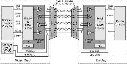 Using TMDS, each channel transmits 8 bits of data (encoded as a 10-bit character) for each color (red/green/blue) serially at up to 165MHz. This allows a pixel rate of 165 megapixels per second (Mpps), which enables a single-link TMDS connection to easily handle computer video resolutions as high as UXGA (1600x1200) as well as 1080p HDTV (1920x1080 with progressive scan). With 8 bits for each color channel, 24-bit color depth is supported, which equates to 16.7 million colors. If more bandwidth is necessary, the DVI standard in particular is designed to support a second TMDS link in the same cable and connector. This link uses three additional TMDS signal pairs (one for each color) and shares the same clock and DDC signals as the primary link. This is called dual-link DVI, and it increases the bandwidth to 330MHz, or 330Mpps, which will handle computer resolutions as high as QXGA (2048x1536). At present, very few flat-panel displays use resolutions high enough to require dual-link DVI. TMDS links include support for Display Data Channel (DDC), a low-speed, bidirectional standard for communication between PCs and monitors, created by the VESA. DDC defines the physical connection and signaling method, whereas the communications and data protocol is defined under the VESA Extended Display Identification Data (EDID) standard. DDC and EDID allow the graphics controller to identify the capabilities of the display so the controller can automatically configure itself to match the display's capabilities. Digital Visual Interface (DVI)The Digital Visual Interface (DVI) was introduced on April 2, 1999 by the Digital Display Working Group (DDWG). The DDWG was formed in 1998 by Intel, Silicon Image, Compaq, Fujitsu, Hewlett-Packard, IBM, and NEC to address the need for a universal digital interface standard between a host system and a display. DVI is based on TMDS and is essentially an updated version of the VESA P&D interface standard that supports higher bandwidths, without the USB and FireWire connections. Unlike P&D and DFP, DVI gained immediate widespread industry support, with 150 DVI products being shown at the Intel Developer Forum in August 1999, only four months after DVI was released. Since then, DVI has become the de facto standard interface for digital video connections. Many, if not most, newer desktop PCs include a DVI connection for digital display support. However, recent and current laptop computers with DVI support implement DVI through a connector on their docking stations or port replicators rather than with a built-in DVI connector. Note To determine whether a particular laptop computer supports DVI output, first determine whether its docking station or port replicator features a DVI port. Next, determine which laptop models support the DVI port. Some vendors, such as IBM, make docking stations and port replicators that have a DVI port, but the DVI port is supported by certain computer models only. Before you purchase a docking station or port replicator to attain DVI compatibility with a particular laptop model, make sure the laptop supports DVI output. As with P&D, DVI allows for both digital and analog connections using the same basic connector. The main difference between P&D and DVI is that DVI eliminates the USB and FireWire connections and adds a second set of TMDS channels for optional use in a dual-link configuration. A single-link DVI connection supports computer resolutions up to UXGA (1600x1200) and WUXGA (1920x1200), as well as video resolutions of HDTV (1920x1280) in either interlaced or progressive scan mode. A dual-link DVI interface adds QXGA (2048x1536) and QSXGA (2560x2048) support, using the same cable with both links active. Even higher resolution displays can be supported with dual DVI ports, each with a dual-link connection. Typical laptop implementations of DVI support single-link resolutions. DVI uses Molex MicroCross connectors in two slightly different designs. The DVI standard was primarily designed to support digital devices; however, for backward compatibility, it can also support analog devices as well. The DVI-D (digital) connector supports only digital devices, whereas the DVI-I (integrated) connector supports both digital and analog devices via the addition of extra pins. Figure 11.10 and Table 11.6 show the DVI-I (integrated) connector and pinout. Figure 11.10. The DVI-I connector.
The DVI-D connector is the same as the DVI-I connector, except that it lacks the analog connections. By virtue of the unique MicroCross connector design, a digital-only device can connect only to receptacles with digital support, and an analog-only device can plug in only to receptacles with analog support. This design feature ensures that an analog-only device cannot be connected to a digital-only receptacle, and vice versa. Figure 11.11 shows the DVI-D connector. The pinout is the same as the DVI-I connector, except for the missing analog signals. The DVI-D connector is widely used on laptop port replicators and docking stations that provide DVI support. Figure 11.11. The DVI-D connector. You can add DVI support to a laptop computer, provided it natively supports DVI, by connecting it to a compatible docking station or port replicator with a DVI port. These are available for selected models of IBM, Dell, and Toshiba laptops, among others. Video Adapter ComponentsAlthough virtually all laptop computers feature external VGA output, the components used for onboard video differ greatly from those used by desktop computers. Desktop video display controllers have traditionally included the following basic components:
The major differences between laptop and desktop graphics include the following:
Tip To determine if you can upgrade to more powerful graphics with your laptop, find out if the laptop uses integrated graphics, a soldered-in-place discrete graphics processor, or a removable graphics card module. If the laptop is part of a product family that offers different graphics processors, it probably uses a removable graphics card module. If so, you might be able to replace it with a better graphics card module. Check with the laptop vendor's parts department or with other users to determine which modules are compatible with your laptop, and order the module. If you upgrade to a better graphics processor module, keep in mind that you will need to install the graphics drivers manually if you ever reinstall the original software and operating system from a restore CD. The following subsections examine discrete graphics processors and motherboard-integrated graphics solutions used by laptops in greater detail. The Video BIOSLaptop computers with discrete graphics processors incorporate a video BIOS, a type of firmware that is similar in construction but completely separate from the main system BIOS. (Other devices in your system, such as SCSI adapters, might also include their own BIOS.) If you turn on your monitor first and look quickly, you might see an identification banner for your laptop's video BIOS at the beginning of the system startup process. If the laptop has chipset-integrated graphics, the chipset emulates the function of the video BIOS. The video BIOS section of a graphics processor includes read-only memory (ROM), which contains basic instructions that provide an interface between the video hardware and the software running on your system. The software that makes calls to the video BIOS can be a standalone application, an operating system, or the main system BIOS. The programming in the video BIOS enables your system to display information on the monitor during the system POST and boot sequences, before any other software drivers have been loaded from disk. The video BIOS also can be upgraded, just like a system BIOS. The BIOS uses a rewritable chip called electrically erasable programmable read-only memory (EEPROM) that you can upgrade with a utility the laptop manufacturer provides. A BIOS you can upgrade using software is referred to as a flash BIOS, and laptops with discrete graphics processors that offer BIOS upgrades use this method. Video BIOS upgrades (sometimes referred to as firmware upgrades) are sometimes necessary when the manufacturer encounters a significant bug in the original programming. Occasionally, a BIOS upgrade is necessary because of a major revision to the video card chipset's video drivers. As a general rule, the video BIOS is a component that falls into the "if it ain't broke, don't fix it" category. Try not to let yourself be tempted to upgrade just because you've discovered that a new BIOS revision is available. Check the documentation for the upgrade, and unless you are experiencing a problem the upgrade addresses, leave the video BIOS alone. The Graphics ProcessorLaptops might use a discrete graphics processor to process and display video, or might use the video features of the motherboard chipset. The graphics processor or motherboard chipset a particular laptop computer uses essentially defines the graphics subsystem's functions and performance levels. Two different laptops that use the same discrete graphics processor or chipset-integrated graphics will have similar, if not identical, video performance and features. Early laptops used a simple frame-buffer design, whereas more recent laptops use graphics accelerators, 3D graphics processors, or integrated chipsets that emulate graphics accelerators or 3D graphics processors. These technologies are compared in Table 11.7.
Today's laptops use either discrete graphics processors or motherboard chipsets that integrate graphics features. The following subsections examine these different approaches to laptop graphics in more detail. Discrete Graphics ProcessorsDiscrete graphics processors are used by many mid-range and most high-end laptops to provide high-speed 2D and 3D acceleration. Because discrete graphics processors are separate from the motherboard chipset and typically use memory separate from the laptop computer's main memory, they usually provide higher performance and more features than typical motherboard-integrated graphics solutions. Typical Features of Recent Mobile Graphics ProcessorsRecent discrete graphics processors from major vendors such as ATI (www.ati.com) and NVIDIA (www.nvidia.com) include features such as the following:
These features are similar to those available on mid-range and high-end desktop graphics processors and boards and are designed to enable laptop computer users to enjoy no-compromise graphics. Memory OverviewSeveral types of memory have been used with discrete graphics processors over the years. However, most recent discrete laptop graphics processors use DDR or DDR-II SDRAM, which are the fastest types of RAM available. Older models might use one of the older RAM types listed in Table 11.8.
SGRAM, DDR, and DDR-II SDRAMwhich are derived from popular motherboard memory technologieshave replaced VRAM, WRAM, and MDRAM as high-speed video RAM solutions. Their high speeds and low production costs have enabled even low-end discrete graphics processors to support 32MB or more of high-speed RAM. SDRAMSynchronous DRAM (SDRAM) is the same type of RAM used on many systems based on processors such as the Pentium III, older Pentium 4s, Athlon, older Athlon XPs, and Duron. This memory is designed to work with bus speeds up to 200MHz and provides performance just slightly slower than SGRAM. SDRAM is used primarily by current low-end laptop graphics processors such as the original ATI Mobility Radeon. SGRAMSynchronous graphics RAM (SGRAM) was designed to be a high-end solution for very fast video adapter designs. SGRAM is similar to SDRAM in its capability to be synchronized to high-speed buses up to 200MHz, but it differs from SDRAM by including circuitry to perform block writes to increase the speed of graphics fill or 3D Z-buffer operations. Although SGRAM is faster than SDRAM, most discrete graphics processor makers have dropped SGRAM in favor of even faster DDR SDRAM in their newest products. DDR SDRAMDouble data rate SDRAM (DDR SDRAM) is the most common video RAM technology on recent video cards. It is designed to transfer data at speeds twice that of conventional SDRAM by transferring data on both the rising and falling parts of the processing clock cycle. Today's mid-range laptop graphics processors such as NVIDIA's GeForce 6800 Go and ATI's Mobility Radeon X300/600 and 700 series use DDR SDRAM for video memory. DDR-II SDRAMThe second generation of DDR SDRAM fetches 4 bits of data per cycle, instead of 2 bits, as with DDR SDRAM. This doubles the performance at the same clock speed. The first graphics processor to support DDR-II was NVIDIA's GeForce FX, which became the top of NVIDIA's line of GPUs in late 2002. Today DDR-II SDRAM is superseded by DDR-III (GDDR3) SDRAM for all mid-range and high-end desktop graphics processors. DDR-III SDRAMDDR-III SDRAM, or GDDR3, is the third generation of DDR SDRAM memory. Because it was specifically developed for graphics use, it is not compatible with the upcoming JEDEC DDR-III specification. The range of operating frequencies and programmable latencies allows GDDR3 memory to offer better performance at reduced cost. To improve bandwidth, GDDR3 offers on-chip termination, increasing bandwidth significantly. GDDR3 memory has now become the standard for mid-range and high-end desktop graphics processors offering better performance at lower cost than DDR-II SDRAM. Video Memory LocationsDepending on the discrete graphics processor used, video memory might be located in one of three places in a typical laptop:
From the standpoint of performance, dedicated memory chips on the motherboard or memory attached to the graphics processor is preferable to a UMA-based system. When a graphics processor is forced to share memory with the system, performance usually suffers. Fortunately, very few discrete graphics processors for laptops use UMA. How Memory Size Affects Display QualityThe amount of memory available for graphics (whether discrete or motherboard chipset-integrated) affects display quality in three ways:
The amount of memory a graphics processor needs to display a particular resolution and color depth is based on a mathematical equation. A location must be present in the adapter's memory array to display every pixel on the screen, and the resolution determines the number of total pixels. For example, a screen resolution of 1024x768 requires a total of 786,432 pixels. If you were to display that resolution with only two colors, you would need only 1 bit of memory space to represent each pixel. If the bit has a value of 0, the dot is black, and if its value is 1, the dot is white. If you use 24 bits of memory space to control each pixel, you can display more than 16.7 million colors because 16,777,216 combinations are possible with a four-digit binary number (224=16,777,216). If you multiply the number of pixels necessary for the screen resolution by the number of bits required to represent each pixel, you have the amount of memory the adapter needs to display that resolution. Here is how the calculation works:
As you can see, displaying 24-bit color (16,777,216 colors) at 1024x768 resolution requires exactly 2.25MB of RAM on the video adapter. However, because laptop graphics processors support memory amounts such as 1MB, 2MB, or 4MB, you would need to use a laptop whose video subsystem has at least 4MB of RAM available to run your system using that resolution and color depth. To use the higher-resolution modes and greater numbers of colors common today, you would need much more memory on your video adapter than the 256KB found on the original IBM VGA. Table 11.9 shows the memory requirements for some of the most common screen resolutions and color depths used for 2D graphics operations, such as photo editing, presentation graphics, desktop publishing, and web page design. Note that the memory requirements are the same for both discrete graphics processors and motherboard chipset-integrated graphics.
From Table 11.9, you can see that a video adapter with 4MB can display 65,536 colors in 1600x1200 resolution mode, but for a true-color (16.8 million colors) display, you would need 8MB of RAM. Note Although very few laptops support 1600x1200 resolutions with their internal displays, many recent models can support external monitors at this resolution. Whether the display is built in to the laptop or is an external model receiving signals through the laptop's VGA port, the amount of memory required is the same for any given resolution and color depth combination. Although 4MB or more of display memory was once rare, this amount or more is very common on today's laptop computers, meaning that high-resolution 2D graphics are possible with most laptops in use today. However, 3D video cards require more memory for a given resolution and color depth because the video memory must be used for three buffers: the front buffer, back buffer, and Z-buffer. The amount of video memory required for a particular operation varies according to the settings used for the color depth and Z-buffer. Triple-buffering allocates more memory for 3D textures than double-buffering but can slow down performance of some games. The buffering mode used by a given 3D video card usually can be adjusted through its properties page. Table 11.10 lists the memory requirements for 3D cards in selected modes.
Note Although 3D adapters typically operate in a 32-bit mode, this does not necessarily mean they can produce more than the 16,777,216 colors of a 24-bit true-color display. Many video processors and video memory buses are optimized to move data in 32-bit words, and they actually display 24-bit color while operating in a 32-bit mode, instead of the 4,294,967,296 colors you would expect from a true 32-bit color depth. Although modern laptops with motherboard chipset-integrated graphics can play 3D games, their 3D performance and support of advanced 3D graphics are relatively poor compared to recent discrete graphics processors. If you spend a lot of time working with graphics and want to enjoy 3D games, you should consider laptops that use high-performance discrete graphics processors with at least 64MB of RAM, such as the ATI Mobility Radeon X300/600/700 or NVIDIA GeForce Go 6 series. Although 2D operations can be performed with as little as 4MB of RAM, 32-bit color depths for realistic 3D operation with large Z-buffers use most of the RAM available on a laptop with 16MB of video memory at 1024x768 resolution; higher resolutions use more than 16MB of RAM at higher color depths. Consequently, laptops with 64MB or more of dedicated video memory are preferred if you want to play 3D games at high resolutions. Motherboard Chipset-Integrated GraphicsJust as low-cost desktop computers typically use chipsets that integrate graphics into the memory controller hub or North Bridge chip, most low-cost and mid-range laptops also use integrated graphics. Integrated graphics reduce the cost of the laptop because the vendor doesn't need to pay for a discrete graphics processor, separate video memory, or the engineering necessary to adapt discrete graphics to a particular laptop motherboard. However, integrated graphics typically offer lower performance, especially for 3D operation, than discrete graphics processors, and older chipsets often lack support for multiple monitors. Systems with integrated graphics also share system memory, which reduces the amount of memory available for the operating system and applications by as much as 32MB or more. Note Depending on the chipset used, some laptops with integrated graphics use a fixed amount of memory for graphics, but those that use Dynamic Video Memory Technology (DVMT) adjust the amount of video memory as required for the application or task being performed, up to the maximum size of memory allowed for video (usually 32MB). For example, 3D gaming or photo editing uses more memory than text editing, and a system with DVMT adjusts the amount of memory used for video accordingly. Major Mobile Chipsets with Integrated GraphicsTable 11.11 provides details about the major mobile integrated graphics chipsets available from Intel and VIA (the two biggest integrated graphics chipset vendors for laptops) for Pentium III-M, AMD Athlon 4, and newer mobile processors. If you are researching the purchase of a new laptop, you can use this table to determine which chipsets might be the most suitable for your needs. If you already have a laptop computer, you can compare its chipset to others.
Tip To determine what chipset your laptop uses, download and install the latest version of SiSoftware Sandra from www.sisoftware.co.uk. Click the Mainboard information icon to get the details you need. Adjusting the Amount of Memory Available for GraphicsIf your system uses integrated graphics, you can adjust the amount of memory available for graphics in two ways:
Many systems that use integrated graphics offer two or more settings for graphics memory size in the system BIOS. To increase (or decrease) the amount of memory available for video use, follow this procedure:
If your laptop uses a system with dynamic memory allocation, a method used by Intel's mobile chipsets, the amount of memory used for graphics varies with the amount of main memory installed as well as with the operating system installed. If your system has less than 256MB of RAM installed, upgrade the memory to 256MB or more to maximize the amount of memory available for graphics. The Video DriverThe software driver is an essential, and often problematic, element of a video display subsystem. The driver enables your software to communicate with the graphics processor in your laptop, whether it is discrete or integrated. You can have a laptop with the fastest mobile processor, discrete graphics processor, and the most efficient memory on the market, but still have poor video performance because of a badly written driver. Although the discrete graphics processor or the motherboard chipset vendor creates the video drivers for laptops, they are usually heavily modified to meet the requirements of the laptop vendor. Consequently, to make sure that all the unique video features of your laptop are properly supported, you should normally get driver updates from the laptop vendor. If your laptop vendor no longer supports your laptop's chipset, you can try generic drivers from the graphics or motherboard chipset maker, but they might not work as well as drivers that have been customized for your system. The video driver also provides the interface you can use to configure your laptop's built-in or external display. On a Windows 9x/Me/2000/XP system, the Display applet found in the Windows Control Panel identifies the monitor and graphics processor installed on your system and enables you to select the color depth and screen resolution you prefer. The driver controls the options available for these settings, so you can't choose parameters the hardware doesn't support. For example, the controls would not allow you to select a 1024x768 resolution with 24-bit color if the adapter has only 1MB of memory. When you click the Advanced button on the Settings page, you see the Properties dialog box for your particular video display adapter. The contents of this dialog box can vary, depending on the driver and the capabilities of the hardware. Typically, on the General page of this dialog box, you can select the size of the fonts (large or small) to use with the resolution you've chosen. Windows 98/Me/2000 (but not Windows XP) also add a control to activate a convenient feature. The Show Settings Icon on Task Bar check box activates a tray icon that enables you to quickly and easily change resolutions and color depths without having to open the Control Panel. This feature is often called QuickRes. The Adapter page displays detailed information about your adapter and the drivers installed on the system, and it enables you to set the refresh rate for your display; with Windows XP, you can use the List All Modes button to view and choose the resolution, color depth, and refresh rate with a single click. The Monitor page enables you to display and change the monitor's properties and switch monitor drivers if necessary. In Windows XP, you can also select the refresh rate on this screen. Laptop External Video ActivationFrom the earliest portable computers to the present day, virtually all laptops have featured an external monitor port. As a consequence, almost all systems also enable you to use the built-in display, the external display, or both displays at the same time, mirroring the contents of the internal display on the external monitor. Most laptop computers require a function key or software command to activate/deactivate the laptop video output signal for external monitors or TV-Out. The activation/deactivation keystroke usually acts as a switch, cycling between the internal display, external display, or both displays simultaneously. In most cases, the simultaneous display setting does not work properly if the native resolution of the external display (such as a projector) does not match the native resolution of the laptop LCD display. This means that the internal display of some laptops needs to be turned off to achieve optimal image quality on the projector, which can be a major inconvenience. In such a case, I've had to add a signal splitter and an extra monitor so I can see what is being projected behind me when I teach a class. Here are some of the most commonly used keys to toggle the internal, external, and dual-display settings:
To change the setting for your display, hold down the Fn (function) key and press the appropriate other key, pausing a few seconds between each keypress. This cycles the display output between internal, external, and simultaneous modes. Caution Although simultaneous display works when the external display is a monitor or projector with the same native resolution as the internal LCD display, it usually doesn't work when a TV is used as the external display through the S-Video (TV-Out) jack. Although the ability to display the contents of the internal display on a monitor can be useful for teaching, presentations, or demonstrations, true multiple-display functionality on laptops has been quite scarce until recently. Multiple Monitor SupportWindows 98 introduced a video display feature that Macintosh systems have had for years: the capability to use multiple monitors on one system to display different parts of the desktop. Windows 98 and Windows Me support up to 9 monitors (and video adapters), each of which can provide a different view of the desktop. Windows 2000 and Windows XP support up to 10 monitors and video adapters. Although multiple-display support has become widespread on desktop computers, either through the installation of secondary display adapters or the recent popularity of dual-head display adapters at mid-range and higher price points, multiple-display support was scarce on laptops until the development of Windows XP. Windows XP has revolutionized multiple display support for laptops by adding a feature called DualView, an enhancement to Windows 2000's multiple-monitor support. DualView supports notebook computers connected to external displays. With systems supporting DualView, the first video port is automatically assigned to the primary monitor. On a notebook computer, the primary display is the built-in LCD display. To set up dual monitors on a laptop or notebook system that supports DualView, start by connecting an external display to the VGA connector on your system. Then use the following instructions to set up the dual monitors in Windows XP:
You can set different resolutions and color depths for each display. Note that using the Extended Desktop requires enough video memory for each display. This is not a problem on most newer systems, but older systems with lower amounts of video memory may have problems with high color depths on both displays. In addition, certain operations, such as playing DVDs and running 3D graphics, require extra video memory, so you may have to adjust display settings. If you have problems, try reducing the color depth on both the internal and external displays. On most laptop and notebook systems with DVD drives and player applications, DVD movies will show only on the primary display. To change the primary display, go to the Settings tab of Display Properties, right-click the display you want, and select Primary. Note Although Windows XP introduced DualView, not every laptop shipped with Windows XP supports DualView. DualView is supported only if the discrete graphics processor or integrated graphics support multiple monitors. 3D Graphics and LaptopsAlthough business software has yet to fully embrace 3D imaging, full-motion graphics are used in sports, first-person shooters, team combat, driving, and many other types of PC gaming. Three-dimensional gaming has become very popular with all types of computer users, and recent laptops now feature 3D graphics capabilities such as lighting, perspective texture, and shading effects that rival those of mid-range desktop graphics cards. The Basics of 3D GraphicsTo construct an animated 3D sequence, a computer can mathematically animate the sequences between keyframes. A keyframe identifies specific points. A bouncing ball, for example, can have three keyframes: up, down, and up. Using these frames as a reference point, the computer can create all the interim images between the top and bottom. This creates the effect of a smoothly bouncing ball. After it has created the basic sequence, the system can then refine the appearance of the images by filling them in with color. The most primitive and least effective fill method is called flat shading, in which a shape is simply filled with a solid color. Gouraud shading, a slightly more effective technique, involves the assignment of colors to specific points on a shape. The points are then joined using a smooth gradient between the colors. A more processor-intensive (and much more effective) type of fill is texture mapping. The 3D application includes patternsor texturesin the form of small bitmaps that it tiles onto the shapes in the image, just as you can tile a small bitmap to form the wallpaper for your Windows desktop. The primary difference is that the 3D application can modify the appearance of each tile by applying perspective and shading to achieve 3D effects. When lighting effects that simulate fog, glare, directional shadows, and others are added, the 3D animation comes very close indeed to matching reality. 3D Graphics Processors for LaptopsUntil the late 1990s, 3D applications had to rely on support from software routines to convert these abstractions into live images. This placed a heavy burden on the system processor in the PC, which has a significant impact on the performance not only of the visual display but also of any other applications the computer might be running. Although graphics cards with 3D acceleration have been available for desktop computers since the late 1990s, it took much longer for both discrete graphics processor and motherboard chipset vendors to develop 3D acceleration for the laptop market. The first discrete graphics processor for laptops to support 3D acceleration was the NVIDIA GeForce 2 Go. GeForce 2 Go was introduced in late 2000, with the first laptops to use it released in early 2001. Other pioneering discrete graphics processors for laptops, ATI's Mobility Radeon and Trident Microsystems' CyberBLADE XP, were introduced in early 2001. All three companies have developed follow-on products that several major brands of laptops use, primarily in their mid-range and high-end models. At about the same time, 3D features began to show up in integrated graphics chipsets as well, although even the best integrated graphics for laptops are slower than discrete graphics processors. Most laptops built in 2002 and later now support some level of 3D acceleration and lighting effects. In fact, today's discrete graphics processors for laptops now support the same advanced 3D graphics and lighting effects that are standard in Microsoft DirectX 9.0, just as the desktop graphics processors do. Consequently, most laptops now enable users to enjoy full-motion 3D graphics in sports, first-person shooters, team combat, driving, and many other types of PC gaming. Table 11.12 compares the 3D support available in recent discrete graphics processors made for laptops. The most powerful and most recent processors in each brand are listed first, with less powerful processors listed afterward.
Virtually all these processors support multiple displays, although only on laptops that provide the necessary connections through docking stations or port replicators. User-Upgradeable Laptop Graphics ModulesUntil recently, upgrading the graphics processor in your laptop was officially "impossible." However, if your laptop uses a discrete graphics processor on a removable module, some clever users have been able to determine which graphics modules available from a laptop vendor's service department would work as plug-compatible replacements. These users purchased the modules as replacement parts and performed the upgrades themselves. However, there are several risks to such "do it yourself" graphics upgrades:
3D Graphics Application Programming InterfacesApplication programming interfaces (APIs) provide hardware and software vendors a means to create drivers and programs that can work quickly and reliably across a wide variety of platforms. When APIs exist, drivers can be written to interface with these APIs rather than directly with the operating system and its underlying hardware. Currently, the leading game APIs include SGI's OpenGL and Microsoft's Direct 3D. OpenGL and Direct 3D (part of DirectX) are available for virtually all leading graphics cards and laptop graphics chipsets. Although the graphics processor vendor must provide OpenGL support, Microsoft provides support for Direct3D as part of a much larger API called DirectX. The latest version of DirectX is DirectX 9.0c, which enhances 3D video support, enhances DirectPlay (used for Internet gaming), and provides other advanced gaming features. For more information about DirectX or to download the latest version, see Microsoft's DirectX website at www.microsoft.com/windows/directx. Note DirectX 9.0c is for Windows 98 and later versions (98SE, Me, 2000, and XP) only. However, Microsoft still provides DirectX 8.0a for Windows 95 users. DirectX Support and 3D GraphicsWhen different 3D graphics processors are compared, the level of DirectX support provided by each processor is often used as a quick way to compare each processor's features. Therefore, it's useful to know about the major 3D features provided by DirectX 7.0, DirectX 8.0, DirectX 8.1, and DirectX 9.0, which are the versions of DirectX supported by recent discrete and integrated graphics processors for laptops. DirectX 7.0 features all basic 3D features (multitexturing, bump mapping, texture compression, stencil buffers) and added hardware transform and lighting and texture compression. DirectX 8.0 and 8.1 add programmable vertex and pixel shaders and antialiasing (8.1 uses a slightly more advanced version of vertex and pixel shaders than 8.0) for much greater realism. Caution The majority of integrated chipsets support DirectX 8.0- or 9.0-level 3D effects, albeit sometimes through slower software rendering rather than faster hardware rendering. DirectX 9.0 adds floating-point color and improved vertex and pixel shaders that can handle longer, more complex programming, thus further improving realism. To learn more about these advanced 3D features, as well as the basic 3D features supported by almost all recent laptops, read the following subsections. Major Features of 3D GraphicsThe basic function of 3D software is to convert image abstractions into the fully realized images that are then displayed on the monitor. The image abstractions typically consist of the following elements:
Using these elements, the abstract image descriptions must then be rendered, meaning they are converted to visible form. Rendering depends on two standardized functions that convert the abstractions into the completed image that is displayed onscreen:
A modern laptop that includes a chipset capable of 3D video acceleration has special built-in hardware that can perform the rasterization process much more quickly than if it were done by software (using the system processor) alone. Most chipsets with 3D acceleration perform the following rasterization functions right on the graphics processor:
Common 3D TechniquesVirtually all 3D graphics processors use the following techniques:
Because these techniques are so common, data sheets for advanced graphics processors frequently don't mention them, although these features are present. Advanced 3D TechniquesThe following subsections detail some of the latest techniques that leading 3D graphics processors use. Not every chip uses every technique. Stencil BufferingStencil buffering is a technique useful for games such as flight simulators in which a static graphic elementsuch as a cockpit windshield frame, which is known as a HUD (heads-up display) and used by real-life fighter pilotsis placed in front of dynamically changing graphics (such as scenery, other aircraft, sky detail, and so on). In this example, the area of the screen occupied by the cockpit windshield frame is not rerendered. Only the area seen through the "glass" is rerendered, saving time and improving frame rates for animation. Z-BufferingA closely related technique is Z-buffering, which originally was devised for computer-aided drafting (CAD) applications. The Z-buffer portion of video memory holds depth information about the pixels in a scene. As the scene is rendered, the Z-values (depth information) for new pixels are compared to the values stored in the Z-buffer to determine which pixels are in "front" of others and should be rendered. Pixels that are "behind" other pixels are not rendered. This method increases speed and can be used along with stencil buffering to create volumetric shadows and other complex 3D objects. Environment-Based Bump Mapping and Displacement MappingEnvironment-based bump mapping introduces special lighting and texturing effects to simulate the rough texture of rippling water, bricks, and other complex surfaces. It combines three separate texture maps (for colors, for height and depth, and for environmentincluding lighting, fog, and cloud effects). This creates enhanced realism for scenery in games and could also be used to enhance terrain and planetary mapping, architecture, and landscape-design applications. This represents a significant step beyond alpha blending. However, a feature called displacement mapping produces even more accurate results. Special grayscale maps called displacement maps have long been used for producing accurate maps of the globe. Microsoft DirectX 9.0 supports the use of grayscale hardware displacement maps as a source for accurate 3D rendering. Texture Mapping Filtering EnhancementsTo improve the quality of texture maps, several filtering techniques have been developed, including MIP mapping, bilinear filtering, trilinear filtering, and anisotropic filtering. These techniques and several others are explained here:
Note Bilinear and trilinear filtering work well for surfaces viewed straight on, but they might not work so well for oblique angles (such as a wall receding into the distance).
TV/Video Output and CaptureLaptop computers can be used with TVs, video players, and video recorders to provide the following benefits:
Before a laptop computer can be used with external video or TV sources or recorders, it needs to have suitable built-in hardware or external peripherals connected to it. However, before you attempt to use a laptop computer with TV or video hardware, it's important to understand the differences between computer and TV signals. In the United States, the National Television Standards Committee (NTSC) established color TV standards in 1953. Some other countries, such as Japan, followed this standard. Many countries in Europe, though, developed more sophisticated standards, including Phase Alternating Line (PAL) and Sequential Couleur A Mémoire (SECAM). Table 11.13 shows the differences among these standards.
Until recently, it was necessary to buy VGA-to-NTSC converters for any laptop you wanted to use with a TV set or VCR. However, most recent laptops now feature a TV-Out (S-Video) port that can be used for this purpose; some low-cost models use the less-desirable composite video port instead. The TV-Out port provides adequate quality for use with a TV set, but if you want to record high-quality video with your laptop, you should use an external VGA-to-NTSC adapter with a feature called genlocking. Genlocking enables the synchronization of signals from multiple video sources or video with PC graphics. This provides the signal stability necessary to obtain adequate results when recording to tape. Adding TV-Out SupportIf your laptop doesn't have a TV-Out (S-Video) port, you can add an external adapter. This adapter does not replace your existing video card but rather connects to it using an external cable. In addition to VGA input and output ports, a video-output device typically has a video-output interface for S-Video and composite video. A few high-end models support HDTV. Most VGA-to-TV converters support the standard NTSC television format and might also support the European PAL format; a few also support the French SECAM format. The display resolution these devices are designed to accept is sometimes limited to straight VGA at 640x480 pixels, although some TV-Out ports and external converters can also handle up to 1280x1024 output resolutions and convert them to NTSC. A few advanced models also support DV (1600x1200) to TV conversion. The converter also might contain an antiflicker circuit to help stabilize the picture because VGA-to-TV products, as well as TV-to-VGA solutions, often suffer from a case of the jitters. Some models can be powered from the laptop's USB port, but most use an AC adapter. Figure 11.13 shows a typical external VGA-to-NTSC solution. It includes a remote control, which makes it easier to adjust the quality of the TV picture and activate special features such as zoom. Figure 11.13. AVerMedia's AVerkey300 Gold PC-to-TV converter features a remote control, Plug and Play operation, and dual-display support for PCs and Macs. It requires an AC power source. (Photo courtesy AVerMedia.) Adding TV Tuner and Video Capture SupportAlthough an increasing number of laptop computers support TV-Out, the TV-Out port doesn't support TV input. If you want to watch TV on your laptop or capture still images or video, you need to add additional hardware. Today, video sources come in two forms:
Analog video can be captured from traditional sources, such as broadcast or cable TV, VCRs, and camcorders using VHS or similar tape standards. This process is much more demanding of storage space and system performance than still images are. Here's why. The typical computer screen was designed to display mainly static images. The computer's capability to store and retrieve these images requires managing huge files. Consider this: A single, full-screen color image in an uncompressed format can require as much as 2MB of disk space; a 1-second video would therefore require 45MB. Likewise, any video transmission you want to capture for use on your PC must be converted from an analog NTSC signal to a digital signal your computer can use. Considering that full-motion video can consume massive quantities of disk space, it becomes apparent that data compression is all but essential. Compression and decompression apply to both video and audio. Not only does a compressed file take up less space, but it also performs better simply because less data must be processed. When you are ready to replay the video/audio, the application decompresses the file during playback. In any case, if you are going to work with video, be sure that your hard drive is large enough and fast enough to handle the huge files that can result. Tip Although today's laptop computers have hard drives as large as 80GB, working with video can quickly use up much of your laptop's disk space. Consider adding an external hard disk with an IEEE 1394 or USB 2.0 port and a capacity of at least 80GB or more to your laptop for video storage, or making frequent backups of captured video with the CD-RW drive typically found in most recent laptop computers. Compression/decompression programs and devices are called codecs. Two types of codecs exist: hardware-dependent codecs and software (or hardware-independent) codecs. Hardware codecs typically perform better; however, they require additional hardware that is not usually available for laptops. Software codecs do not require hardware for compression or playback, but they typically do not deliver the same quality or compression ratio. Two of the major codec algorithms are JPEG and MPEG. These codec algorithms are described in the following list:
If you will be capturing or compressing video on your computer, you'll need software based on standards such as Microsoft's DirectShow (the successor to Video for Windows and ActiveMovie), Real Network's Real Producer series, or Apple's QuickTime Pro. Players for files produced with these technologies can be downloaded free from the vendors' websites. To play or record video with your laptop, you need some extra hardware and software:
You can capture individual screen images or full-motion video for reuse in several ways:
TV tuners that plug into the USB port are available from a wide variety of sources, including Hauppauge (www.hauppauge.com), StarTech, AVerTech, Pinnacle Systems (www.pinnaclesys.com), and others. Some devices support only USB 1.1, whereas others also support the faster data-transfer rates of USB 2.0 (Hi-Speed USB). In most cases, users rate the results with USB 1.1compatible devices as acceptable, but noticeably less sharp than a normal TV signal would be. This is due primarily to the low data rate (12Mbps) supported by the USB 1.1 port. Devices that support the 480Mbps transfer rate of USB 2.0 provide better quality, but you need to add a USB 2.0 (Hi-Speed USB) CardBus card to your laptop if it doesn't have a Hi-Speed USB port already installed or built in to the unit. Most TV tuners also provide still or full-motion capture, but you can also use dedicated video-capture devices or use web cams that include video inputs. These units capture still or moving images from NTSC video sources, such as camcorders and VCRs. Although image quality is limited by the input signal, the results are still good enough for presentations and desktop publishing applications. These devices work with displays configured to use 8-, 16-, and 24-bit color depths and usually accept video input from VHS, Super VHS, and Hi-8 devices. As you might expect, however, Super VHS and Hi-8 video sources give better results, as do configurations using more than 256 colors. Tip For best color and screen quality when watching TV or capturing video, set your display for 24-bit or 32-bit color. For the best video capture results, use DV camcorders equipped with IEEE 1394 (i.LINK/FireWire) connectors; they can output high-quality digital video directly to your computer without the need to perform an analog-to-digital conversion. Although many laptop computers feature built-in IEEE 1394 ports, you need to install an IEEE 1394 CardBus card into those that lack these ports if you want to capture output from a DV camcorder. Your second-best option is to use a USB 2.0equipped personal video recorder (PVR) or video capture device. These devices are optimized to provide high-quality digital conversions from analog video such as TV shows and existing analog videotape. A PVR also enables you to digitally record a TV show and watch it on a delayed basis and enjoy high-speed digital fast-forward and rewind. If you want to use both USB 2.0 and IEEE 1394a devices with your laptop computer and don't have either port type already, Adaptec (www.adaptec.com) offers a CardBus card that provides both port types in a single Type II PC Card form factor. If you want to capture analog video or still images from a TV or VCR, the quality of the captured video or still images is affected by the speed of the port used (USB 2.0 ports are faster than USB 1.1 ports), especially for analog video, as well as the connection used between the video source and the laptop. If possible, use the S-Video connector on your TV or VCR for the connection; this is the same type of connector used by almost all laptops with built-in TV-Out and is also supported by most add-on TV tuner or video capture devices. S-Video separates color (chroma) and brightness (luma) into separate signals. Composite video (which uses a single RCA jack) provides a lower-quality picture than S-Video does. Troubleshooting Laptop Video ProblemsTroubleshooting laptop video problems is more difficult than troubleshooting problems with desktop video because one of the most popular techniques, replacing the video card, is not possible on many laptops. Even on laptops that offer a removable video module, the video module is difficult to remove and expensive to replace. Generally, such replacements are done only when the video chip inside the adapter has failed or the user wants to upgrade to a better graphics processor. However, there are still many ways to determine the cause of laptop video problems and solve (or work around) some of them. Troubleshooting Graphics AccelerationIf your laptop's graphics subsystem includes a graphics accelerator (as virtually all of them have for some time), the Display adapter's Advanced properties page has a Performance tab that contains a Hardware Acceleration slider you can use to control the degree of graphic display assistance provided by your adapter hardware. In Windows XP, the Performance page is referred to as the Troubleshoot page. Setting the Hardware Acceleration slider to the Full position activates all the adapter's hardware acceleration features. If you're not certain of which setting is the best for your situation, use this procedure: Move the slider one notch to the left to address mouse display problems by disabling the hardware's cursor support in the display driver. This is the equivalent of adding the SWCursor=1 directive to the [Display] section of the System.ini file in Windows 9x/Me. If you are having problems with 2D graphics in Windows XP only, but 3D applications work correctly, move the slider to the second notch from the right to disable cursor drawing and acceleration. Moving the slider another notch (to the third notch from the right in Windows XP or the second notch from the right in earlier versions) prevents the adapter from performing certain bit-block transfers; it disables 3D functions of DirectX in Windows XP. With some drivers, this setting also disables memory-mapped I/O. This is the equivalent of adding the Mmio=0 directive to the [Display] section of System.ini and the SafeMode=1 directive to the [Windows] section of Win.ini (and the SWCursor directive mentioned previously) in Windows 9x/Me. Moving the slider to the None setting (the far left) adds the SafeMode=2 directive to the [Windows] section of the Win.ini file in Windows 9x/Me. This disables all hardware acceleration support on all versions of Windows and forces the operating system to use only the device-independent bitmap (DIB) engine to display images, rather than bit-block transfers. Use this setting when you experience frequent screen lockups or receive invalid page fault error messages. Note If you need to disable any of the video hardware features listed earlier, this often indicates a buggy video or mouse driver. If you download and install updated video and mouse drivers, you should be able to revert to full acceleration. You should also download an updated version of DirectX for your version of Windows. Troubleshooting Display ColorsIf you're trying to reproduce onscreen color graphics with a color printer and the colors don't match between your display and your printer, look for a tab called Color Management in the Advanced section of the Display properties page (click Settings, Advanced to display these tabs). You can select a color profile for your monitor to enable more accurate color matching for use with graphics programs and printers. If onscreen color is too dark, too light, or colors are off, use the Color tab to adjust color balance, brightness, contrast, and gamma (see Figure 11.14). Figure 11.14. The Color tab for the ATI Mobility Radeon processor can be used to adjust overall desktop brightness; color curves for red, blue, and green; and game screen brightness with the game gamma button. If the flat-panel display panel or external monitor can't display 16-bit, 24-bit, or 32-bit color, the display drivers might be corrupted. Delete the video display adapter listing in Device Manager and restart the computer so it will reload the drivers. Download and install updated drivers if necessary. Troubleshooting 3D Acceleration Quality IssuesIf you are having problems with 3D game display performance or display quality, you have two options you can try if installing new drivers doesn't improve the situation:
If your laptop supports 3D graphics, its graphics driver will usually have two tabs in the Advanced dialog box that you can use to adjust 3D graphics performance and screen quality:
Typically, dialog boxes like the one shown in Figure 11.15 enable you to adjust the settings in the direction of performance (less detailed 3D graphics with greater screen display speed) or quality (greater 3D graphics detail with lower screen display speed) and to fine-tune specific settings for anisotropic filtering, antialiasing, textures, MIP mapping, and Z-buffer depth. Figure 11.15. Use the Direct3D dialog box (left) to adjust visual quality and performance settings for DirectX games. Use the OpenGL dialog box (right) to adjust visual quality and performance settings for OpenGL games. Tip Because laptop computers are often slower than desktop computers in both 3D graphics performance and processor speed, try the Performance settings first for best results, unless you have a laptop with a processor faster than 2GHz. Troubleshooting Internal DisplaysProblem: No picture. Solution: Press the key combination used to switch the display between the internal and external monitors. If you have cycled through the key combinations to switch the display and still don't see a picture on the internal display, check the contrast and brightness controls. Dual-scan and passive-matrix panels often have a sliding control on the side of the flat-panel display. Active-matrix models might use key combinations to adjust these settings, or they might not have adjustments. If you still don't see a picture after making these adjustments, plug your system into an external monitor and try the troubleshooting steps listed in the next section. If no picture appears on the external monitor either, your laptop's graphics processor might have failed. Problem: Picture is surrounded by a wide black border (refer to Figure 11.2). Solution: Adjust the Display properties to use the native resolution of the display. Problem: Black line or box across part or all of the display. Solution: Transistors in the flat-panel display have failed. Replace the display panel as soon as possible. Use an external display until you can replace the display. Troubleshooting External DisplaysProblem: No picture. Solution: If the LED on the front of the monitor is yellow or flashing green, the monitor is in power-saving mode. Press the key combination to switch the display to the external monitor. If both the internal display and external display are blank, move the mouse or press Alt+Tab on the keyboard and wait up to 1 minute to wake up the system if the system is turned on. If the LED on the front of the monitor is green, the monitor is in normal mode (receiving a signal), but the brightness and contrast are set incorrectly on the monitor. Adjust them. If no lights are lit on the monitor, check the power and power switch. Check the surge protector or power director to ensure that power is going to the monitor. Replace the power cord with a known-working spare if necessary. Retest. Replace the monitor with a known-working spare to ensure that the monitor is the problem. Check data cables at the monitor and laptop video port. If the monitor is plugged into a port replicator or docking station, shut down the monitor and computer, remove the port replicator or docking station, and plug the monitor directly into the laptop's VGA port. If the display works when it is plugged directly into the laptop, the port replicator or docking station is defective. Problem: Jittery picture quality. Solution: For flat-panel display monitors, use display-adjustment software or onscreen menus to reduce or eliminate pixel jitter and pixel swim. For all monitors, check cables for tightness at the video card and the monitor (if removable). Here are some other actions to take:
For CRT monitors, check refresh-rate settings; reduce them until acceptable picture quality is achieved. Here are some other actions to take:
Troubleshooting Drivers and Video ProcessorsProblem: The display works at startup (DOS) but not in Windows. Solution: If you have an acceptable picture quality in MS-DOS mode (system boot) but no picture in Windows, most likely you have an incorrect or corrupted video driver installed in Windows. Boot Windows 9x/Me in Safe Mode (which uses a VGA driver), boot Windows 2000/XP in Enable VGA mode, or install the VGA driver and restart Windows. If Safe Mode or VGA Mode works, get the correct driver for the graphics processor and reinstall. Problem: Can't select the desired color depth and resolution combination. Solution: Verify that the graphics processor is properly identified in Windows and that the video memory is working properly. Use diagnostic software provided by the graphics processor maker to test the video memory. If the hardware is working properly, check for new drivers. If the system uses integrated graphics with a fixed video memory size, make sure the maximum size for the frame buffer has been selected in the system BIOS setup program. If the video memory size varies by installed memory, install more memory (up to a total of 256MB or more) to provide more memory for use by the display. Problem: Can't select desired refresh rate. Solution: Verify that the card and monitor are properly identified in Windows. Obtain updated drivers for the card and monitor. DisplayMate DisplayMate is a unique diagnostic and testing program designed to thoroughly test your laptop's graphics processor and display. It is somewhat unique in that most conventional PC hardware diagnostics programs do not emphasize video testing the way this program does. I find it useful not only in testing whether a graphics processor is functioning properly but also in examining video displays. You easily can test the image quality of a display, which allows you to make focus, centering, brightness and contrast, color level, and other adjustments much more accurately than before. If you are purchasing a new monitor or laptop computer, you can use the program to evaluate the sharpness and linearity of the display and to provide a consistent way of checking each monitor you are considering. If you use projection systems for presentationsas I do in my PC hardware seminarsyou will find it invaluable for setting up and adjusting the projector. DisplayMate also can test a laptop's video circuits thoroughly. It sets the video circuits into each possible video mode so you can test all the adapter's capabilities. It even helps you determine the performance level of your card, both with respect to resolution and colors as well as speed. You can then use the program to benchmark the performance of the display, which enables you to compare one type of video adapter system to another. Visit www.displaymate.com for more information. | |||||||||||||||||||||||||||||||||||||||||||||||||||||||||||||||||||||||||||||||||||||||||||||||||||||||||||||||||||||||||||||||||||||||||||||||||||||||||||||||||||||||||||||||||||||||||||||||||||||||||||||||||||||||||||||||||||||||||||||||||||||||||||||||||||||||||||||||||||||||||||||||||||||||||||||||||||||||||||||||||||||||||||||||||||||||||||||||||||||||||||||||||||||||||||||||||||||||||||||||||||||||||||||||||||||||||||||||||||||||||||||||||||||||||||||||||||||||||||||||||||||||||||||||||||||||||||||||||||||||||||||||||||||||||||||||||||||||||||||||||||||||||||||||||||||||||||||||||||||||||||||||||||||||||||||||||||||||||||||||||||||||||||||||||||||||||||||||||||||||||||||||||||||||||||||||||||||||||||||||||||||||||||||||||||||||||||||||||||||||||||||||||||||||||||||||||||||||||||||||||||||||||||||||||||||||||||||||||||||||||||||
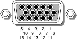
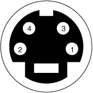
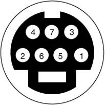
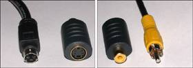
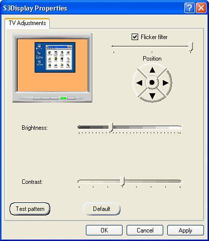
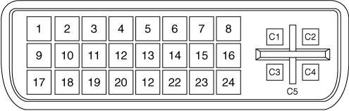
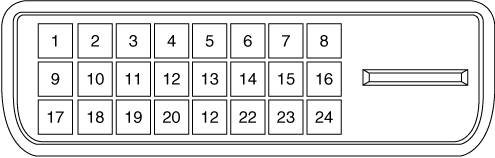
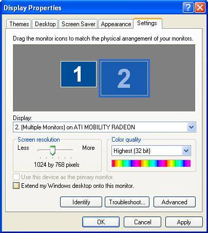

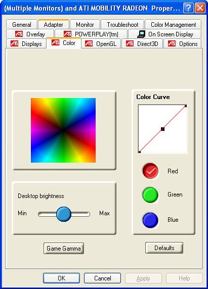
EAN: 2147483647
Pages: 180