1.5 Introduction to Interface Terminology
| | ||
| | ||
| | ||
1.5 Introduction to Interface Terminology
It is important to understand certain fundamental principles which will arise regularly in the discussion of interfacing and communications.
1.5.1 Data Rate versus Baud Rate
The data rate of an interface is the rate at which information is carried (sometimes referred to as the information rate), whereas the baud rate of an interface is the modulation rate or number of data 'symbols' per second. Although in many cases the two are equivalent, modulation schemes exist which allow for more than one bit to be carried per baud, such as by using multi-level encoding, by using a form of phase-shift keying or other such channel code (see section 3.6).
Data rate is normally quoted as so many kilo- or megabits per second (Kb/s, Mb/s) and this must normally include any capacity for control and additional data. The term baud rate is used more widely in computer and telecommunications systems than it is in audio and video interfacing, but it is useful to understand the distinction.
1.5.2 Synchronous, Asynchronous and Isochronous Communications
The receiving device must be able to determine in which time slot it is to register each bit of data which arrives and there are two approaches to achieving this end. In synchronous communications a clock signal normally accompanies the data, either on a separate wire or modulated with the data (see Chapter 3) and this is used to synchronize the receiver's clock to that of the transmitter. Each bit of data may be latched at the receiver on one of the edges of a separate clock, or the clock may be extracted from the modulated data using a suitable phase-locked loop (PLL), as described in section 3.5.
In asynchronous communications the clocks of the transmitter and receiver are not locked directly, but must have an almost identical frequency. The tolerance is often around 1%. In such a protocol each byte of data is prefixed with a start bit and followed by one or more stop bits (see Figure 1.6) and the phase of the receiver's clock is adjusted at the trailing edge of the start bit. The following data bits are then clocked in according to the receiver's clock, which should remain sufficiently in phase with the transmitted data over the duration of one byte to ensure correct reception . The receiver's clock is then resynchronized at the start of the next data byte. Such an approach is often used in computer systems for exchange of data with remote locations over a modem, for example, where the gaps between received bytes may be variable and data flow may not be regular.
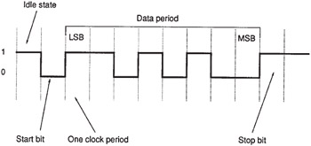
Figure 1.6: In asynchronous data transfer each data byte is normally preceded by a start bit and followed by a stop bit to synchronize the receiver.
In isochronous systems one master clock is used to synchronize all receiving devices, and data transmission and reception is clocked with relation to this source.
1.5.3 Uni- and Bi-Directional Interfaces
In a uni-directional interface data may only be transmitted in one direction, and no return path is allowed from the receiver back to the transmitter. In a bi-directional interface a return path is provided and this allows for two-way communications. The return path is often used in a simple serial situation to send back handshaking information to the transmitter, telling it whether or not the data was received satisfactorily. Unfortunately such an approach is not particularly useful in digital audio and video interfacing because the data in these situations is transferred in real time, making retransmission in the case of an error an unrealistic concept.
A simplex interface is one which operates in one direction only; a half-duplex interface is one which operates in both directions, but only one at a time; and a full-duplex interface is one capable of simultaneous transmission and reception.
1.5.4 Clock Signals
A clock signal may be needed, as described above, to synchronize the receiver. In digital audio and video interfacing a variety of methods are used to ensure synchronism between transmitter and receiver which are discussed in detail in the sections concerned . In general two important clock frequencies exist, that is the 'word clock' which indicates the sampling frequency or rate of sample words over the interface, and the 'bit clock' which indicates the rate of individual data bits. Some interfaces, such as the AES/EBU audio interface, combine the bit clock with the data using a modulation scheme or channel code known as bi-phase mark and indicate the starts of sample words using a violation of the modulation scheme which is easily detected by the receiver. This approach avoids the need for additional lines to carry clock signals and the data is said to be 'self-clocking'. In contrast, an interface such as Mitsubishi's audio interface carries the bit clock and word clock signals on individual wires.
An alternative approach is that used in the so-called 'MADI' audio interface (see Chapter 4) in which the transmitter and receiver are both locked to a common reference clock signal and the data is transmitted asynchronously, using a buffer at both ends of the interface to allow for flexibility in timing. This is a form of isochronous approach. The different methods are summarized in Figure 1.7.
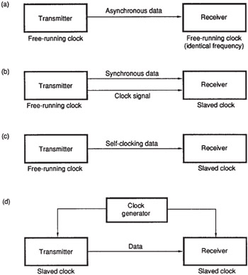
Figure 1.7: A number of approaches may be used to ensure synchronization in data transfer. (a) Asynchronous transfer relies on transmitter and receiver having identical frequencies, requiring only the receiver's clock phase to be adjusted by the start bit of each byte. (b) In synchronous transfer the data signal is accompanied by a separate clock. (c) A form of synchronous transfer involves modulating the data in such a way that a clock signal is part of the channel code. (d) In the isochronous approach both devices are locked to a common clock.
1.5.5 Multiplexing
A multiplexed interface is one which carries more than one data signal over a single channel. This is normally achieved using time-division multiplexing (TDM), whereby different time slots in the data stream carry different kinds of information (see Figure 1.8). Here the channel capacity is divided up between the data streams using it, and a multiplexer takes control of the insertion of data into the correct time slots. A demultiplexer at the receiving end extracts the data from each time slot and produces a number of separate data streams.
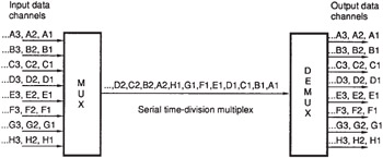
Figure 1.8: In a serial time-division multiplex a number of input channels share a single high-speed link. Each time slot carries a data packet for each channel.
The AES/EBU audio interface is a simple example of a multiplexed interface, since left and right channel data are multiplexed over the same communications channel, with samples of data for each channel taking alternate time slots on the interface. The MADI interface is a more complicated example in which 56 channels of audio data are multiplexed onto one communications channel a result of which is that the data rate of the communications channel must be extremely high in order to ensure that data for each audio channel can still be carried in real time.
Thus a multiplexed interface must have a data rate high enough to handle the total data rate of all the data streams which are to be multiplexed onto it, otherwise delays will arise as data queues to use the link. In a computer network it is often acceptable to have short delays where the network is shared between many users, since one can wait for a file to load from a remote server, but for real-time applications such as audio and video it is clearly unacceptable to have a shared network which cannot always carry each channel without breaks or queuing.
1.5.6 Buffering
Buffering is sometimes used at transmitting and receiving ends of an interface to store a number of samples of data temporarily. The buffer is normally a RAM (Random Access Memory) store configured in the FIFO (First In, First Out) mode whose input may be addressed separately to its output (see Figure 1.9). Using such a buffer it is possible to iron out irregularities in data flow, since erratic data arriving at the input may be stored in the buffer and read out at a more regular rate after a short delay. The approach will be successful provided that the average rate of flow into the buffer equals the average rate of flow out of it, and the buffer is big enough to accommodate the irregularities which may arise at its input, otherwise the buffer will either overflow or become empty after a time. A disadvantage of the approach is the delay which arises between input and output, which may be undesirable.
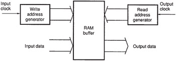
Figure 1.9: A memory buffer may be used as a temporary store to handle irregularities in data flow. Data samples are written to successive memory locations and read out a short time later under control of the read clock.
| | ||
| | ||
| | ||
EAN: 2147483647
Pages: 120