6.6 Considerations in Video Environments
| | ||
| | ||
| | ||
6.6 Considerations in Video Environments
Audio and video/film have traditionally required synchronization for the purposes of achieving lip sync. Film and video are both discrete in that they have frames , and when audio was analog synchronizing to sufficient accuracy for lip sync caused no difficulty. Now that audio is also digital, it too is made up of discrete information and more accurate synchronizing with video becomes necessary. In environments where digital audio is used with video signals it is important for the audio sampling rate to be locked to the same master clock as the video reference. The same applies to timecode signals which may be used with digital audio and video equipment. A number of proposals exist for incorporating timecode within the standard two-channel interface, each of which has different merits, and these will be discussed below.
6.6.1 Relationships between Video Frame Rates and Audio Sampling Rates
People using the PAL or SECAM television systems are fortunate in that there is a simple integer relationship between the sampling frequency of 48 kHz used in digital audio systems for TV and the video frame rate of 25 Hz (there are 1920 samples per frame). There is also a simple relationship between the other standard sampling frequencies of 44.1 and 32 kHz and the PAL/SECAM frame rate, as was shown in Table 4.2. Users of NTSC TV systems (such as the USA and Japan) are less fortunate because the TV frame rate is 30/1.001 ( roughly 29.97) frames per second, resulting in a non-integer relationship with standard audio sampling frequencies. The sampling frequency of 44.056 kHz was introduced in early digital audio recording systems that used NTSC VTRs, as this resulted in an integer relationship with the frame rate. For a variety of historical reasons it is still quite common to encounter so-called 'pull-down' sampling frequencies in video environments using the NTSC frame rate, these being 1/1.001 times the standard sampling frequencies, which mainly serves to complicate matters.
The standard two-channel interface's channel status block structure repeats at 192 sample intervals, and in 48 kHz systems there are exactly ten audio interface frames per PAL/SECAM video frame, simplifying the synchronization of information contained in channel status with junctures in the TV signal and making possible the carrying of EBU timecode signals in channel status as described below.
As described by Shelton 9 and others 10 , 11 it is desirable to source a master audio reference signal centrally within a studio operation, just as a video reference is centrally sourced. These two references are normally locked to the same highly stable rubidium reference, which in turn may be locked to a standard reference frequency broadcast by a national transmitter. As shown in Figure 6.11, the overall master clock contained in a central apparatus room will be used to lock the video SPG (distributed as 'black and burst' video), the audio reference signal generator (distributed as a standard AES11 reference signal) and the colour subcarrier synthesizer. The video reference is used in turn to lock timecode generators. Appropriate master clock frequencies and division ratios may be devised for the application in question.
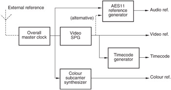
Figure 6.11: In video environments all audio, video and timecode sync references should be locked to a common clock.
The sync point between audio and video reference signals defined in AES11 is the half amplitude point of the leading edge of line sync of line 1 of the video frame in systems where there is an integer number of AES frames per video frame. This is synchronized to the start of the X or Z audio preamble. The situation is complicated with NTSC video since there is not an integer number of audio samples per frame. The desired alignment of audio preamble and video line sync only occurs once every five frames and an indicator is supposed to be included in the video reference to show which frame acts as the sync point.
An alternative approach to video sync is found on some audio equipment, especially digital tape recorders . Here the audio device accepts a video sync reference and derives its sample clock by appropriate multiplication and division of this reference internally. DIP switches may be provided on the audio device to select the appropriate frame rate so that the correct ratio results.
6.6.2 Referencing of VTRs with Digital Audio Tracks
Video tape recorders (VTRs), both analog and digital, are often equipped with digital audio tracks. Digital VTRs are really data recorders with audio and video interfaces. The great majority of the data is video samples and the head rotation is locked to the video field timing. Part of each track is reserved for audio data, which uses the same heads and much of the same circuitry as the video on a time-division basis. As a result the audio sampling rate has to be locked to video timing so that the correct number of audio and video samples can be assembled in order to record a track.
At the moment the only audio sampling rate supported by digital VTRs is 48 kHz. This causes no difficulty in 625/50 systems as there are exactly 960 sample periods in a field and a phase-locked loop can easily multiply the vertical rate to produce a video synchronous 48 kHz clock. Alternatively, line rate can be multiplied by 384/125. However, the 0.1% offset of 525 line systems makes the actual field rate 59.94 Hz. The fields are slightly longer than at 60 Hz and in 60 fields there will be exactly 48 048 sample periods. Unfortunately this number does not divide by 60 without a remainder. The smallest number of fields which contain a whole number of samples is five. This makes the generation of the audio sampling clock more difficult, but it can be obtained by multiplying line rate by 1144/375.
When a DVTR is recording using analog audio inputs, the heads rotate locked to input video, which also determines the audio sampling rate for the ADCs in the machine and there is no difficulty. On replay, the synchronism between video and audio is locked in the recording and the audio sampling rate on the output will be locked to station reference. Any receiving device will need to slave to the replay audio sampling rate. On recording with a digital audio input, it is necessary that the digital audio source is slaved to the input video of the DVTR. This can be achieved either by taking a video-derived audio sampling rate reference from the DVTR to the source, or by using a source which can derive its own sampling rate from a video input. The same video timing is then routed to both the source and the DVTR.
If these steps are not followed, there could be an audio sampling rate mismatch between the source and destination and inevitably periodic corruption will occur. With modern crystal-controlled devices it is surprising how long an unlocked system can run between corruptions. It is easy mistakenly to think a system is locked simply because it works for a short whilst when in fact it is not and will shows signs of distress if monitored for longer.
In some VTRs with digital audio tracks it has been possible for there to arise a phase relationship between the digital audio outputs of a VTR and the video output which is different each time the VTR is turned on, causing difficulties in the digital transfer of audio and video data to another VTR. When the phase relationship is such that the incoming digital audio signal to a VTR lies right on the boundary between two sample slots of its own reference there is often the possibility of sample slips or repeats when timing jitter causes vacillation of sync between two sample periods. This highlights the importance of fixing the audio/video phase relationship.
Manufacturers of video recorders, though, claim that the solution is not as simple as it seems, since in editing systems the VTR may switch between different video sync references depending on the operational mode. Should the audio phase always follow the video reference selection of the VTR? In this case audio reframing would be required at regular points in the signal chain. A likely interim solution will be that at least the phase of the house audio reference signal with relation to the house video sync will be specified, providing a known reference sync point for any reframing which might be required in combined audio/video systems.
6.6.3 Timecode in the Standard Two-Channel Interface
In section 4.8 the possibility of including 'sample address' codes in the channel status data of the interface was introduced. Such a code is capable of representing a count of the number of samples elapsed since midnight in a binary form, and when there is a simple relationship between the audio sampling frequency and the video frame rate as there is with PAL TV signals, it is relatively straightforward to convert sample address codes into the equivalent value in hours, minutes, seconds and frames used in SMPTE/EBU timecode.
At a sampling frequency of 48 kHz the sample address is updated once every 4 ms, which is ten times per video frame. At NTSC frame rates the transcoding is less easy, especially since NTSC video requires 'drop-frame' SMPTE timecode to accommodate the non-integer number of frames per second. A further potential difficulty is that the rate of update and method of transcoding for sample address codes is dependent upon the audio sampling frequency, but since this is normally fixed within one studio centre the issue is not particularly important.
Discussions ran for a number of years on an appropriate method for encoding SMPTE/EBU timecodes in a suitable form within the channel status or user bits of the audio interface. At the time of writing there is no published standard for this purpose, although a number of European broadcasters have adopted the non-standard procedure described below. There is also potential for incorporating timecode messages into the HDLC packet scheme determined for the user bit channel in AES18 (see section 4.7.1). The advantage of this option is that the data transfer rate in AES18 is independent of the audio sampling frequency, within limits, so the timecode could possibly be asynchronous with the audio, video, or both, if necessary. Such a scheme makes it difficult to derive a phase reference between the video frame edge and the timecode frame edge, but additional bits are proposed in this option to indicate the phase offset between the two at regular points in the video frame.
An important proposal was made and adopted by a number of European broadcasters 12 , which replaced the local sample address code in bytes 1417 of channel status with four bytes of conventional SMPTE/EBU timecode. These bytes contained the BCD (Binary Coded Decimal) time values for hours, minutes, seconds and frames, as replayed from the device in question, in the following manner:
-
Byte 14 = frames (a four-bit BCD value for both tens and units of frames)
-
Byte 15 = seconds (ditto for seconds)
-
Byte 16 = minutes (ditto for minutes)
-
Byte 17 = hours (ditto for hours)
The time-of-day sample address bytes (1821) are replaced by time-of-day timecode in the same way. At 48 kHz with EBU timecode the time-code value is thus repeated ten times per frame.
| | ||
| | ||
| | ||
EAN: 2147483647
Pages: 120
- Basic MPLS Configuration
- Basic MPLS VPN Overview and Configuration
- Implementing VPNs with Layer 2 Tunneling Protocol Version 3
- Implementing AToM for Like to Like Circuits
- Case Study 2: Implementing Multi-VRF CE, VRF Selection Using Source IP Address, VRF Selection Using Policy-Based Routing, NAT and HSRP Support in MPLS VPN, and Multicast VPN Support over Multi-VRF CE