5.4 AES47: Audio Over ATM
| | ||
| | ||
| | ||
5.4 AES47: Audio Over ATM
Asynchronous transfer mode (ATM) is a protocol for data transmission over high speed data networks that operates in a switched fashion and can extend over wide or metropolitan areas. It typically operates over SONET (synchronous optical network) or SDH (synchronous digital hierarchy) networks, depending on the region of the world. Switched networks involve the setting up of specific connections between a transmitter and one or more receivers, rather like a dialled telephone network (indeed this is the infrastructure of the digital telephone network). Data packets on ATM networks consist of a fixed 48 bits, typically preceded by a five-byte header that identifies the virtual channel of the packet.
AES47 7 defines a method by which linear PCM data, either conforming to AES3 format or not, can be transferred over ATM. There are various arguments for doing this, not least being the increasing use of such networks for data communications within the broadcasting industry and the need to route audio signals over longer distances than possible using standard digital interfaces. There is also a need for low latency, guaranteed bandwidth and switched circuits, all of which are features of ATM. Essentially an ATM connection is established in a similar way to making a telephone call. A SETUP message is sent at the start of a new ˜call' that describes the nature of the data to be transmitted and defines its vital statistics. The AES47 standard describes a specific professional audio implementation of this procedure that includes information about the audio signal and the structure of audio frames in the SETUP at the beginning of the call.
For some reason bytes are termed octets in ATM terminology, so this section will follow that convention. Audio data is divided into subframes and each subframe contains a sample of audio as well as optional ancillary data and protocol overhead data, as shown in Figure 5.7. The setup message at the start of the call determines the audio mode and whether or not this additional data is present. The subframe should occupy a whole number of octets and the length of the audio sample should be such that the subframe is 8, 16, 24, 32 or 48 bits long. The ancillary data field, if it is present, is normally used for carrying the VUC bits from the AES3 subframe, along with a B bit to replace the P (parity) bit of the AES3 subframe (which has little relevance in this new application). The B bit in the '1' state indicates the start of an AES3 channel status block, taking the place of the Z preamble that is no longer present. This data is transmitted in the order BCUV.
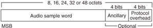
Figure 5.7: General audio subframe format of AES47.
The protocol overhead bits, if present, consist of a sequencing bit followed by three data protection bits (used for error checking). These sequencing bits are assembled from all the subframes in an ATM cell , rather as channel status bits are assembled from successive AES3 subframes to form a sequencing word. The first four bits of this form the sequencing number, the point of which is to act as an incremented count of ATM cells since the start of the call. Bits 57 act as protection bits for the sequencing word, bit 8 is even parity for the first eight bits, and bits 912 (if present) can form a second sequencing number that can be used to align samples from multiple virtual circuits carrying nominally time-aligned signals (see Figure 5.8).
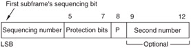
Figure 5.8: Components of the sequencing word in AES47.
Samples are packed into the ATM cell either ordered in time, in multichannel groups or by channel, as shown in Figure 5.9. Only certain combinations of channels and data formats are allowed and all the channels within the stream have to have the same resolution and sampling frequency, as shown in Table 5.2.
| AAL code (hex) [*] | Subframe length (bytes) | Audio resolution | Ancillary bits | Protocol bits | Grouping | No. of audio channels |
|---|---|---|---|---|---|---|
| 56 02 | 4 | 24 | 4 | 4 | Temporal | 2 |
| 56 01 | 4 | 24 | 4 | 4 | N/A | 1 |
| 06 02 | 3 | 24 |
|
| Temporal | 2 |
| 06 01 | 3 | 24 |
|
| N/A | 1 |
| 56 85 | 4 | 24 | 4 | 4 | Multichannel | 60 |
| [*] This should be signalled within the second and third octets of the user -defined AAL part of the SETUP message that is an optional part of the ATM protocol for setting up calls between sources and destinations. | ||||||
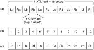
Figure 5.9: Packing of audio subframes into ATM cells. (a) Example of temporal ordering with two channels, left and right. ˜a', ˜b', ˜c', etc., are successive samples in time for each channel. Co-temporal samples are grouped together. (b) Example of multichannel packing whereby concurrent samples from a number of channels are arranged sequentially. (c) Example of ordering by channel, with a number of samples from the same channel being grouped together. (If the number of channels is the same as the number of samples per cell, all three methods turn out to be identical.)
Four octets in the user-defined AAL part of the SETUP message that begins a new ATM call define aspects of the audio communication that will take place. The first byte contains so-called ˜qualifying information', only bit 4 of which is currently specified indicating that the sampling frequency is locked to some global reference. The second byte indicates the subframe format and sample length, whilst the third byte specifies the packing format. The fourth byte contains information about the audio sampling frequency (32, 44.1 or 48 kHz), its scaling factor (from 0.25 up to 8 times) and multiplication factor (e.g. 1/1.001 or 1.001/1 for ˜pull-down' or ˜pull-up'modes). It also has limited information for varispeed rates.
There is provision within the standard for the sender to include a local clock that ticks once per second. It is expected that cells will be blocked such that a block consists of either eight cells or eight sets of samples. The User Indication (UI) bit in the cell header should be set to 1 in the first and last cells of the first block following a clock tick. This can be used to derive a pulse train related to the sampling frequency.
| | ||
| | ||
| | ||
EAN: 2147483647
Pages: 120
- Chapter I e-Search: A Conceptual Framework of Online Consumer Behavior
- Chapter III Two Models of Online Patronage: Why Do Consumers Shop on the Internet?
- Chapter VI Web Site Quality and Usability in E-Commerce
- Chapter VII Objective and Perceived Complexity and Their Impacts on Internet Communication
- Chapter XI User Satisfaction with Web Portals: An Empirical Study