4.5 Auxiliary Data in the Standard Two-Channel Interface
| | ||
| | ||
| | ||
4.5 Auxiliary Data in the Standard Two-Channel Interface
As stated earlier, the four bits of auxiliary data in each subframe may be used for additional LSBs of audio resolution, if more than 20 bits of audio data are needed per sample. Alternatively the auxiliary data may be used to carry information associated with the audio channel. In many items of equipment manufactured to date they remain unused.
It was proposed to the CCIR in 1987 that the aux bits would prove useful for a good voice quality channel which could be used for coordination (talkback) purposes in broadcasting 21 . Typically in a radio broadcast studio the programme source (say a studio) sends a stereo programme to a destination (say a continuity suite) along with a good voice quality link for coordination purposes (see Figure 4.8). A feed of cue programme (normally mono), together with a coordination channel and perhaps additional data, is returned from the destination. It was proposed that in digital studio environments all of these signals could be carried over a single standard two-channel interface in each direction by sampling the coordination voice channel at exactly one-third of the main audio's sampling frequency and coding it linearly at 12 bits per sample, resulting in a data rate exactly one-fifth that of the main audio channel. (Main audio channel @ 48kHz, 20 bits; Data rate = 960 000 bits per second; Coordination channel @ 16kHz, 12 bits; Data rate = 192 000 bits per second.) At such a data rate, a main sampling rate of 48 kHz would allow for a coordination channel bandwidth of about 7 kHz.
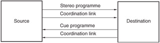
Figure 4.8: In broadcasting a coordination link often accompanies the main programme, and cue programme is fed back to the source, also with coordination.
Capacity exists in the two-channel interface for two 12-bit coordination samples, one in channel 1's subframe ('A' coordination) and one in channel 2's ('B' coordination). They are inserted four bits at a time, as shown in Figure 4.9, with the four LSBs of the 'A' signal going into the first aux word in the block (designated by the Z preamble), followed by the four LSBs of the 'B' signal in the next subframe, and so on for three frames , whereon all 12 bits will have been transmitted for each signal. The process then starts over again. The Z preamble thus acts as a sync point for the coordination channels, and the sampling frequencies of the coordination channels are locked to that of the main audio.
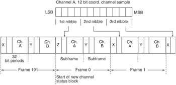
Figure 4.9: The coordination signal is of lower bit rate to the main audio and thus may be inserted in the auxiliary nibble of the interface subframe, taking three subframes per coordination sample.
This arrangement proves very satisfactory because the correct talkback always accompanies a programme signal, the cue programme may be in stereo, and only two hard links are necessary. The user bit channel of the interface can be used to carry any additional control data. In the 1990 revision of CCIR Rec. 647 this modification was taken on board, and forms part of that standard. It was also adopted by the EBU in the 1992 revision of Tech. 3250-E, and appears as an annex to AES3-1992 (for information purposes only). In order to indicate that the aux bits are being used for this purpose, byte 2 of the channel status word (see section 4.8) is used. The first three bits of this byte are set to '010' when a channel's aux bits carry a coordination signal of this type.
| | ||
| | ||
| | ||
EAN: 2147483647
Pages: 120