2.14 Introduction to Video Compression
| | ||
| | ||
| | ||
2.14 Introduction to Video Compression
Video signals exist in four dimensions: these are the attributes of the sample, the horizontal and vertical spatial axes and the time axis. Compression can be applied in any or all of those four dimensions. MPEG-2 assumes eight-bit colour difference signals as the input, requiring rounding if the source is ten bit. The sampling rate of the colour signals is less than that of the luminance. This is done by a down-sampling of the colour samples horizontally and generally vertically as well. Essentially an MPEG-2 system has three parallel simultaneous channels, one for luminance and two for colour difference, which after coding are multiplexed into a single bitstream.
Figure 2.38(a) shows that spatial redundancy is redundancy within a single image, for example repeated pixel values in a large area of blue sky. Temporal redundancy (b) exists between successive images.
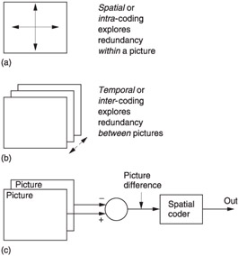
Figure 2.38: (a) Spatial or intra-coding works on individual images. (b) Temporal or inter-coding works on successive images. (c) In MPEG inter-coding is used to create difference images. These are the compressed spatially.
Where temporal compression is used, the current picture is not sent in its entirety; instead the difference between the current picture and the previous picture is sent. The decoder already has the previous picture, and so it can add the difference to make the current picture. A difference picture is created by subtracting every pixel in one picture from the corresponding pixel in another pixel.
A difference picture is an image of a kind, although not a viewable one, and so should contain some kind of spatial redundancy. Figure 2.38(c) shows that MPEG-2 takes advantage of both forms of redundancy. Picture differences are spatially compressed prior to transmission. At the decoder the spatial compression is decoded to recreate the difference picture, then this difference picture is added to the previous picture to complete the decoding process.
Whenever objects move they will be in a different place in successive pictures. This will result in large amounts of difference data. MPEG-2 over-comes the problem using motion compensation. The encoder contains a motion estimator that measures the direction and distance of motion between pictures and outputs these as vectors that are sent to the decoder. When the decoder receives the vectors it uses them to shift data in a previous picture to resemble the current picture more closely. Effectively the vectors are describing the optic flow axis of some moving screen area, along which axis the image is highly redundant. Vectors are bipolar codes that determine the amount of horizontal and vertical shift required.
In real images, moving objects do not necessarily maintain their appearance as they move. For example, objects may turn , move into shade or light, or move behind other objects. Consequently motion compensation can never be ideal and it is still necessary to send a picture difference to make up for any shortcomings in the motion compensation.
Figure 2.39 shows how this works. In addition to the motion-encoding system, the coder also contains a motion decoder. When the encoder outputs motion vectors, it also uses them locally in the same way that a real decoder will, and is able to produce a predicted picture based solely on the previous picture shifted by motion vectors. This is then subtracted from the actual current picture to produce a prediction error or residual which is an image of a kind that can be spatially compressed.
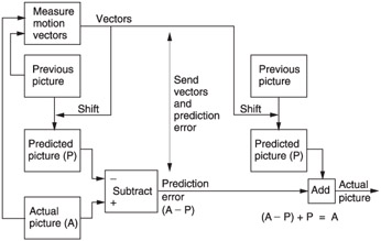
Figure 2.39: A motion-compensated compression system. The coder calculates motion vectors which are transmitted as well as being used locally to create a predicted picture. The difference between the predicted picture and the actual picture is transmitted as a prediction error.
The decoder takes the previous picture, shifts it with the vectors to recreate the predicted picture and then decodes and adds the prediction error to produce the actual picture. Picture data sent as vectors plus prediction error are said to be P coded.
The simple prediction system of Figure 2.39 is of limited use as in the case of a transmission error, every subsequent picture would be affected. Channel switching in a television set would also be impossible . In practical systems a modification is required. The approach used in MPEG is that periodically some absolute picture data is transmitted in place of difference data.
This absolute picture data, known as I or intra pictures, is interleaved with pictures which are created using difference data, known as P or predicted pictures. The I pictures require a large amount of data, whereas the P pictures require fewer data. As a result the instantaneous data rate varies dramatically and buffering has to be used to allow a constant transmission rate.
The I picture and all the P pictures prior to the next I picture are called a group of pictures (GOP). For a high compression factor, a large number of P pictures should be present between I pictures, making a long GOP. However, a long GOP delays recovery from a transmission error. The compressed bitstream can only be edited at I pictures.
Bi-directional coding is shown in Figure 2.40. Where moving objects reveal a background this is completely unknown in previous pictures and forward prediction fails. However, more of the background is visible in later pictures. In the centre of the diagram, a moving object has revealed some background. The previous picture can contribute nothing, whereas the next picture contains all that is required.
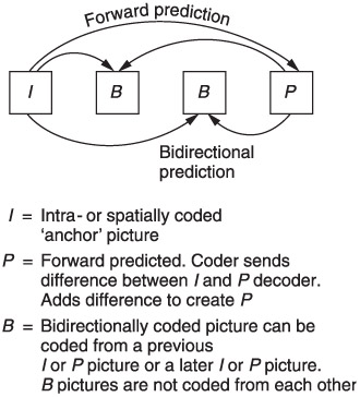
Figure 2.40: In bi-directional coding, a number of B pictures can be inserted between periodic forward predicted pictures. See text.
Bi-directional coding uses a combination of motion compensation and the addition of a prediction error. This can be done by forward prediction from a previous picture or backward prediction from a subsequent picture. It is also possible to use an average of both forward and backward prediction. On noisy material this may result in some reduction in bit rate. The technique is also a useful way of portraying a dissolve.
Typically two B pictures are inserted between P pictures or between I and P pictures. As can be seen, B pictures are never predicted from one another, only from I or P pictures. A typical GOP for broadcasting purposes might have the structure IBBPBBPBBPBB . Note that the last B pictures in the GOP require the I picture in the next GOP for decoding and so the GOPs are not truly independent. Independence can be obtained by creating a closed GOP which may contain B pictures but which ends with a P picture.
Bi-directional coding is very powerful. Figure 2.41 is a constant quality curve showing how the bit rate changes with the type of coding. On the left, only I or spatial coding is used, whereas on the right an IBBP structure is used having two bi-directionally coded pictures in between a spatially coded picture ( I ) and a forward predicted picture ( P ). Note how for the same quality the system that only uses spatial coding needs two and a half times the bit rate that the bi-directionally coded system needs.
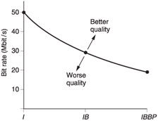
Figure 2.41: Bi-directional coding is very powerful as it allows the same quality with only 40% of the bit rate of intra-coding. However, the encoding and decoding delays must increase. Coding over a longer time span is more efficient but editing is more difficult.
Clearly information in the future has yet to be transmitted and so is not normally available to the decoder. MPEG-2 gets around the problem by sending pictures in the wrong order. Picture reordering requires delay in the encoder and a delay in the decoder to put the order right again. Thus the overall codec delay must rise when bi-directional coding is used. This is quite consistent with Figure 2.36 in which it was shown that as the compression factor rises the latency must also rise.
Figure 2.42 shows that although the original picture sequence is IBBPBBPBBIBB , this is transmitted as IPBBPBBIBB so that the future picture is already in the decoder before bi-directional decoding begins. Note that the I picture of the next GOP is actually sent before the last B pictures of the current GOP.
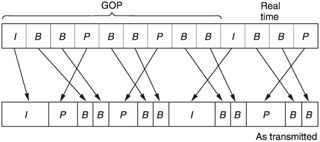
Figure 2.42: Comparison of pictures before and after compression showing sequence change and varying amount of data needed by each picture type. I, P, B pictures use unequal amounts of data.
Figure 2.42 also shows that the amount of data required by each picture is dramatically different. I pictures have only spatial redundancy and so need a lot of data to describe them. P pictures need fewer data because they are created by shifts of I picture using vectors and then adding a prediction error picture. B pictures need the least data of all because they can be created from I or P .
With pictures requiring a variable length of time to transmit, arriving in the wrong order, the decoder needs some help. This takes the form of picture-type flags and time stamps.
| | ||
| | ||
| | ||
EAN: 2147483647
Pages: 120