8.4 Testing Digital Video Interfaces
| | ||
| | ||
| | ||
8.4 Testing Digital Video Interfaces
Once video and audio are converted to the digital domain, they become data, or numbers, and if those numbers can be delivered to the other end of a digital interface unchanged then the interface has not caused any loss of quality. This is one of the strengths of digital technology. In the absence of data reduction techniques, the quality is determined in the conversion process and can then be maintained in transmission and recording. In contrast analog signals are subject to generation loss in every recording and to noise and distortion in every transmission. This analog heritage has led to a philosophy where the analog waveform is monitored at every stage so that some adjustment can be made to minimize the quality loss. The waveform monitor and vectorscope tradition is so strong that despite the transition to the radically different digital technology many people think no new monitoring methods are needed.
Unfortunately, traditional analog testing techniques reveal nothing about a digital interface or recorder. Consider the system of Figure 8.6, which could be composite or component. An ADC converts the input waveform to data that are transmitted by the interface. A DAC converts the received data to analog video once more. If a waveform monitor and vectorscope are connected to the DAC, what information is revealed about the interface? If it is assumed that the interface is not suffering bit errors, the monitoring tells us how good the ADC and DAC are, but reveals nothing about the performance of the interface. The interface could be working with 20 dB of noise immunity, or it could be within a whisker of failure. Should the system be marginal such that one bit fails per minute, this will be invisible on an analog monitoring system in the presence of programme material and may just be detectable on colour bars. If the problem is due to a phase-locked loop drifting in an SDI receiver or damp penetration in a cable, it is going to get worse and in the absence of a warning the result will be a sudden failure.
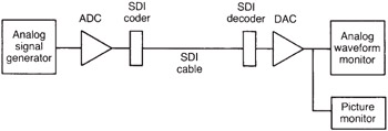
Figure 8.6: Testing waveforms in the analog domain as shown here reveals nothing about the performance margin of the digital interface.
Three distinct testing areas are required in digital video systems. First, on installation, it should be possible to verify that the link is working with an adequate safety margin and that the length of the link is not excessive for the cable type selected. Second, it is necessary to test the data integrity of the link to ensure that the BER (bit error rate) is acceptable and remains acceptable when the system is stressed or margined beyond the conditions it will experience in service. Third, digital systems can suffer from a problem having no parallel in the analog domain. This is the protocol error where the data transmission is flawless but the two units concerned cannot understand each other.
Although the SDI signal is digital in that it carries discrete data, it is an analog waveform as far as the cable and receiver equalizer are concerned. Waveform distortions will occur in the cable and noise and jitter will be added. The magnitude of these distortions indicates the likely reliability of the channel. Figure 8.7 shows that a correctly functioning digital receiver is specifically designed to reject the analog waveform distortions by making discrete decisions. By definition, in doing so it denies us knowledge of the signal quality. Thus what is needed is a complementary approach. Instead of rejecting the distortions to obtain discrete data, what is needed is a system that rejects the data in order to measure the magnitude of the distortions.
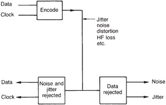
Figure 8.7: The reception process is deliberately designed to reject analog waveform distortions whereas only by measuring these can signal integrity be assessed. Thus the measurement process is diametrically opposed to normal reception and needs special techniques.
One approach is to assess the eye pattern generated by the received waveform. After equalization the eye opening should be clearly visible, and the size of the opening should be consistent with the length and type of cable used. If it is not, the noise and/or jitter margin may be inadequate. However, testing the eye pattern on the SDI requires a fast oscilloscope. Some test equipment samples the SDI waveform at high speed and buffers it so it can be seen on a conventional display. Many SDI receivers have a dedicated, buffered, test point for eye pattern monitoring.
Inspection of the eye pattern is acceptable for establishing that the basic installation is sound and has proper signal levels, termination impedance and equalization, but is not very good at detecting infrequent impulsive noise. Contact noise from electrical power installations such as air conditioners is unlikely to exist for long enough to find an eye pattern display. The technique of signature analysis is better suited to impulsive noise problems.
| | ||
| | ||
| | ||
EAN: 2147483647
Pages: 120