7.6 Synchronizing
| | ||
| | ||
| | ||
7.6 Synchronizing
The component interface carries a multiplex of luminance and colour difference samples and it is necessary to synchronize the demultiplexing process at the receiver so that the components are not inadvertently transposed. As conventional analog syncs are discarded, horizontal and vertical synchronizing must also be provided. In the case of serial transmission it is also necessary to identify the position of word boundaries so that correct deserialization can take place. These functions are performed by special bit patterns known as timing reference and identification signals (TRS-ID) sent with each line. TRS-ID differs only slightly between formats. Figure 7.11 shows the location of TRS-ID. Immediately before the digital active line location is the SAV (start of active video) TRS-ID pattern, and immediately after is the EAV (end of active video) TRS-ID pattern. These unique patterns occur on every line and continue throughout the vertical interval.
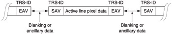
Figure 7.11: The active line data is bracketed by TRS-ID codes called SAV and EAV.
Each TRS-ID pattern consists of four symbols: the same length as the component multiplex repeating structure. In this way the presence of a TRS-ID does not alter the phase of the multiplex. Three of the symbols form a sync pattern for deserializing and demultiplexing (TRS) and one is an identification symbol (ID) that replaces the analog sync signals. The first symbol contains all ones and the next two contain all zeros. This bit sequence cannot occur in active video, even due to concatenation of successive pixel values, so its detection is reliable. As the transition from a string of ones to a string of zeros occurs at a symbol boundary, it is sufficient to enable unambiguous deserialization, location of the ID symbol and demultiplexing of the components. Whatever the word length of the system, all bits should be either ones or zeros during TRS.
The fourth symbol in the ID contains three data bits, H, F and V. These bits are protected by four redundancy bits which form a seven-bit Hamming codeword.
Figure 7.12(a) shows how the Hamming code is generated. Single bit errors can be corrected and double bit errors can be detected according to the decoding table in (b).
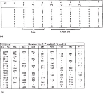
Figure 7.12: The data bits in the TRS are protected with a Hamming code which is calculated according to the table in (a). Received errors are corrected according to the table in (b) where a dot shows an error detected but not correctable.
Figure 7.13(a) shows the structure of the TRS-ID. The data bits have the following meanings:
-
H is used to distinguish between SAV, where it is set to 0, and EAV where it is set to 1.
-
F defines the state of interlace and is 0 during the first field and 1 during the second field. F is only allowed to change at EAV. In interlaced systems, one field begins at the centre of a line, but there is no sync pattern at that location so the field bit changes at the end of the line in which the change took place.
-
V is 1 during vertical blanking and 0 during the active part of the field. It can only change at EAV.
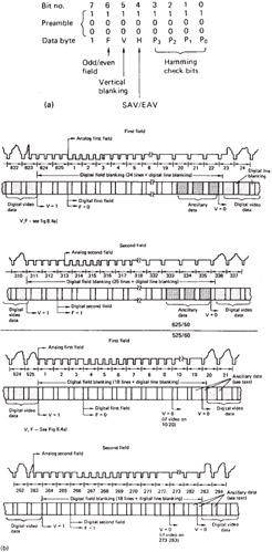
Figure 7.13: (a) The four-byte synchronizing pattern which precedes and follows every active line sample block has this structure. (b) The relationships between analog video timing and the information in the digital timing reference signals for 625/50 (above) and 525/60 (below).
Figure 7.13(b) (top) shows the relationship between the sync pattern bits and 625 line analog timing, whilst below is the relationship for 525 lines.
Figure 7.14 shows a decode table for SD TRS which is useful when interpreting logic analyser displays.
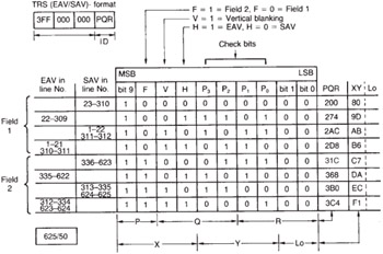
Figure 7.14: Decode table for component TRS.
The same TRS-ID structure is used in SMPTE 274M and 296M HD. It differs in that the HD formats can support progressive scan in which the F bit is always set to zero.
| | ||
| | ||
| | ||
EAN: 2147483647
Pages: 120