Hardware-Monitoring Facilities
|
| < Day Day Up > |
|
Hardware-monitoring tools and facilities gradually are becoming mandatory attributes of the architecture of any contemporary computer system. Such tools usually are built into contemporary chipsets.
Unfortunately, unlike Via chipsets and others, the most popular Intel chipsets are not equipped with built-in hardware-monitoring tools.
However, despite the lack of such tools in the Intel chipset architecture, some motherboards implement these capabilities. They use advanced special-purpose chips such as LM78 and LM79 from National Semiconductor or W83781D and W83782D from Winbond Electronics. A diagram that shows the use of the Winbond W83782D chip is in Fig. 6.2.
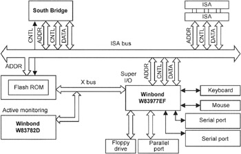
Figure 6.2: Including hardware-monitoring and input/output chips in the computer architecture
Note that some motherboard manufacturers that release products based on advanced chipsets with hardware-monitoring facilities are not satisfied with the standard functional capabilities provided by such chipsets. Because of this, they often use the special-purpose chips previously mentioned, or their analogues. For example, Asus, one of the leading motherboard manufacturers, often uses its own monitoring chips. The PC Health Monitoring function implemented on the basis of the Application-Specific Integrated Circuit (ASIC) AS99127F chip serves as a good example of this approach (Fig. 6.2). Asus and other manufacturers use the same approach when implementing networking functions and several additional controllers, such as IEEE1394.
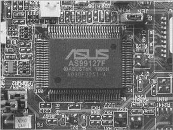
Figure 6.3: Hardware-monitoring chip on the Asus motherboard
The use of specialized hardware-monitoring chips is justified because they often provide better parameters than the built-in hardware-monitoring facilities of the chipset components. These parameters include the number of monitored parameters and measurement accuracy. The latter is crucial in overclocked modes, especially when approaching maximum voltages. In these modes, even one-hundredth of a volt becomes important. Inadequate measurement precision can distort the result, cause incorrect actions, and, consequently, increase the probability of failure.
Fig. 6.4 shows the structure of a hardware-monitoring chip from Winbond: the W83782D Winbond H/W Monitoring IC. Fig. 6.5 shows the LM78/LM79 chip from National Semiconductor. These illustrations also show possible connections of probes and sensors, as well as variants of supplying voltages of different values and polarity to the chip inputs. These chips often are used for hardware monitoring in the architecture of contemporary motherboards.
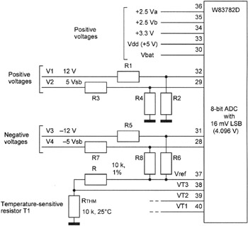
Figure 6.4: Internal structure of the W83782D chip and diagram of probe connections
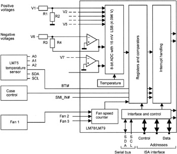
Figure 6.5: Internal structure of the LM78/LM79 chip and diagram of probe connections
The 8-bit Analog-to-Digital Converter (ADC) serves as the basis for the internal structure of these and similar devices. It ensures the input and conversion of 256 input-signal values with positive polarities. The operating range of the ADC is 0 V to 4.096 V, with an increment of 16 millivolts (mV): 4.096/256 = 0.016. To widen the range of input voltages, external or internal resistor dividers must be used. The nominal values of their elements depend on the voltage levels being controlled. This allows the processing of voltages within a range of 5 V to 12 V.
To ensure correct operation of the measurement methods, it is necessary to coordinate their input resistance with the output resistances of the probes. This gives the best signal-to-noise ratio. Coordination can be achieved using sequential resistors or special electronic circuits such as repeaters (with a common collector (CC), common source (CS), etc.).
The nominal resistance of the coordinating resistors influences the voltage measurement results. This probably causes the problems some motherboards experience with hardware monitoring, such as the indication of excessive values of the voltages under control. The hardware-monitoring facilities installed on the motherboard may indicate a CPU core supply of 1.7 V, even though the installed value didn't exceed 1.65 V. This likely is caused by an inadequate design of additional coordinating cascades, but, it could be due to the high noise level, related to unsatisfactory wiring of such motherboards.
Besides controlling positive voltages, it is also possible to input and control negative voltages, such as -5 V or -12 V. For this purpose, the previously mentioned chips use operational amplifiers in the inverting connection (as shown in Fig. 6.5). The coordination of the input levels with the required ADC range is achieved using appropriate resistors that define the input resistance of cascades and values of the feedback for operational amplifiers. The recommended values of external resistors, depending on the voltages to be measured, are in Table 6.1.
| Voltage to be measured (V) | R1 or R3 (kilohm) | R2 or R4 (kilohm) | Output voltage of the chip (V) |
|---|---|---|---|
| +2.5 | 0 | - | +2.5 |
| +3.3 | 0 | - | +3.3 |
| +5 | 6.8 | 10 | +2.98 |
| +12 | 30 | 10 | +3 |
| -12 | 240 | 60 | +3 |
| -5 | 100 | 60 | +3 |
The previously mentioned chips also provide the possibility of measuring the temperatures of the elements being controlled. Generally, thermal resistors are used as sensors. The resistance of thermal resistors depends on the temperature. Usually, these sensors are connected as shown in Fig. 6.4. The internal resistance of the thermal resistor changes with the temperature being measured. The electric current and voltage of this element (which is connected to the supply voltage via the 10-kilohm resistor) change accordingly. The change of the voltage on this thermal resistor is registered by the ADC in the hardware-monitoring chip, similar to the method used to control supply voltages.
Instead of a thermal resistor, a transistor in diode connection can be used for temperature measurement, as shown in Fig. 6.6, a. The operating principle of such sensor is based on the dependence between the threshold opening voltage of the p-n-silicon junction and the temperature. As a result of this effect, the threshold voltage changes almost linearly with the temperature, with a negative gradient of 2.3 mV/sec (dV ~ 1/T). In Fig. 6.6, a, the voltage on the 2N3904 transistor, connected via the resistor to the reference voltage of 3.6 V, will decrease with the temperature growth. To test this effect experimentally, you can mount a circuit comprising a silicon diode, a resistor, and a standard battery (4.5 V). The voltage on the diode will decrease if you heat it with a soldering iron (for no longer than 3 seconds).
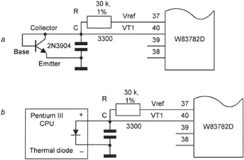
Figure 6.6: Methods for connecting the W83782D chip with different semiconductor thermal sensors— the 2N3904 transistor (a) and the thermal diode built into the Pentium III chip (b)
With a method similar to the one that uses a transistor to control the temperature mode of the CPU, thermal diodes sometimes can be integrated with the Pentium III processor chips. The use of thermal diodes, instead of traditional thermal resistors, can be explained quite easily. Most contemporary chips, including processors, are created on the basis of p-n-junctions that perform the functions of transistors, diodes, and even resistors and capacitors. The recommended minimum value of the current for a built-in thermal diode is -5 micro-ampere (μA); the maximum value is -300 μA.
The diagram for the connection of the thermal diode built into the Pentium III processor to the W83782D chip is in Fig. 6.6, b. The reference voltage is 3.6 V.
When evaluating the readings taken from such sensors, it is necessary to account for the maximum values of the CPU core temperature (the maximum T-junction, shown as T1) and of error (T2). This error is caused by the spatial temperature gradient within the processor chip and the finite speed of the heat propagation. It is also necessary to take into account the effects of the constantly changing spatial temperature distribution, caused by the CPU workload fluctuations. Because of this, the developers advise increasing the T2 value by another error related to temperature measurements. The value of this error is approximately 1°C (33°F).
Thus, when using a thermal diode as a temperature sensor for the Pentium III FC-PGA and SC242 (Slot 1) processors, it is best to take the value of T1-T2-1 as the maximum allowed temperature.
For the Pentium 4 processor, the thermal diode is connected in a similar way.
When using a traditional thermal resistor as a temperature sensor, it is expedient to consider the maximum temperature value of Pentium III/4 processors equal to the maximum case temperature. This usually equals 75°C (167°F). (See Tables 6.2 and 6.3.)
| Processor | T1(°C) | T2 (°C) |
|---|---|---|
| 500E | 85 | 1.9 |
| 533EB | 85 | 2.0 |
| 550E | 85 | 2.1 |
| 600E | 82 | 2.3 |
| 600EB | 82 | 2.3 |
| 650 | 82 | 2.5 |
| 667 | 82 | 2.5 |
| 700 | 80 | 2.7 |
| 733 | 80 | 2.8 |
| 750 | 80 | 2.8 |
| 800 | 80 | 3.0 |
| 800EB | 80 | 3.0 |
| 850 | 80 | 3.3 |
| 866 | 80 | 3.3 |
| 933 | 75 | 3.6 |
| Thermal diode output | SC242 (Slot 1) PIII (contacts) | FC-PGA PIII (contacts) | 423 PGA P4 (contacts) |
|---|---|---|---|
| Anode | B14 | AL31 | H38 |
| Cathode | B15 | AL29 | E39 |
AMD Athlon and AMD Duron processors, as well as early Intel products, have no built-in thermal sensors. Therefore, control of the thermal mode of such processors is implemented using external sensors, usually installed near the Slot A or Slot 1 processors, or within the Socket A (Socket 462) or Socket 370 slots for the processors of the PGA or FC-PGA form factors (Figs. 6.7 and 6.8). To ensure normal operation of thermal sensors and to obtain correct temperature values, motherboard manufacturers provide thermal contact between the sensors and processor cases. To prevent mechanical deformation or even damage to the thermal sensor connection, it is wise to control the quality of the thermal contact.
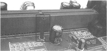
Figure 6.7: External temperature sensor for Slot 1 processors
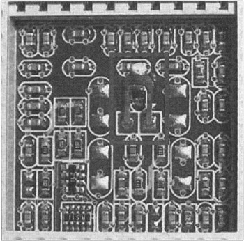
Figure 6.8: External temperature sensor installed within the Socket A slot
When considering specific characteristics of temperature measurements using LM78/LM79 chips, note that the LM75 chip is recommended for use as a sensor. Despite the single input contact for connecting the external thermal sensor, it is possible to connect up to eight LM75 devices. In this case, the available ISA, I2C SDA, SCL, A0, A1, and A2 interface lines are used.
Note that the previously mentioned chips and similar ones used in hardware monitoring do not need calibration. In general, they do not provide such functions to end users. Correct, precise operation is achieved using sensors and connection methods recommended by manufacturers. As a rule, chip architecture is programmable.
The main parameters of the previously described chips — as well as those of other chips, such as W83781D, W83783S, and W83L784R from Winbond, that are oriented toward relatively inexpensive systems and mobile computers — are outlined in Tables 6.4-6.6. For comparison, the main parameters of the hardware-monitoring tools integrated into the VT82C686A chip are also presented. Until recently, this chip was often used in Via chipsets.
| Parameters | W83781D | W83782D | W83783S | W83L784R |
|---|---|---|---|---|
| Temperature control (input lines) | 3 | 3 | 3 | 2 and 1-on-chip |
| Voltage control (input lines) | 5(+), 2(-) | 9 | 6 | 4 |
| Fan control (input lines) | 3 | 3 | 3 | 2 |
| Case integrity control, open/closed (input lines) | 1 | 1 | 1 | - |
| Typical values of monitored voltage (V) | VcoreA, VcoreB, +3.3, +5, +12, -12, -5 | Vcore, +3.3, +5, +12, -1 2, -5, +5 Vsb, Vbat, 1 reserved | Vcore, +3.3, +5, +12, -12, -5 | Vcore, +3.3, +5, Battery |
| Voltage precision (%) (max.) +/- | 1 | 1 | 1 | 1 |
| Temp. precision (°C) (max.) +/- | 3 | 3 | 3 | 3 |
| Built-in ADC (bits) | 8 | 8 | 8 | 8 |
| Interface | ISA, I2C | ISA, I2C | ISA, I2C | ISA, I2C |
| Supply voltage (V) | 5 | 5 | 5 | 5 |
| Current (mA) | 1 | 5 | 5 | 2 |
| Case form-factor | 48p LQFP | 48p LQFP | 24p SOP | 20p SSOP |
| Parameters | LM78 and LM79 |
|---|---|
| Temperature control (input lines) | 1 and sensor-on-chip |
| Voltage control (input lines) | 5(+), 2(-) |
| Fan control (input lines) | 3 |
| Typical values of monitored voltage (V) | 2.5Va, 2.5Vb, +3.3, +5, +12, -5, -12 |
| Voltage precision (%) (max.) | 1 |
| Temperature precision (°C) (max.) | 3 |
| Fan rpm precision (%) (max.) | 10 |
| Built-in ADC (bits) | 8 |
| Interface | ISA, I2C |
| Supply voltage (V) | 5 |
| Current (mA) | 1 |
| Case form-factor | VG244A (PQFP) |
| Parameters | VT82C686A |
|---|---|
| Temperature control (input lines) | 2 and 1-on-chip |
| Voltage control (input lines) | 4(+) and 1-on-chip |
| Fan control (input lines) | 2 |
Most motherboard manufacturers continue to release motherboards that include hardware-monitoring facilities based on specialized chips, even though more advanced chipsets that implement improved architecture are designed and released constantly by manufacturers such as Intel, Via Technologies, Ali, and SiS. These chipsets are more sophisticated and offer a significantly wider range of functional capabilities than their predecessors. As a rule, these chipsets provide various monitoring tools, including hardware-monitoring.
|
| < Day Day Up > |
|
EAN: 2147483647
Pages: 111